warning JEEP GRAND CHEROKEE 2017 WK2 / 4.G User Guide
[x] Cancel search | Manufacturer: JEEP, Model Year: 2017, Model line: GRAND CHEROKEE, Model: JEEP GRAND CHEROKEE 2017 WK2 / 4.GPages: 372
Page 185 of 372
To enable the ParkSense Active Park Assist
system, push the ParkSense Active Park As-
sist switch once (LED turns on).
To disable the ParkSense Active Park Assist
system, push the ParkSense Active Park As-
sist switch again (LED turns off).
When the ParkSense Active Park Assist sys-
tem is enabled the “Active ParkSense
Searching - Push OK to Switch to Perpen-
dicular” message will appear in the instru-
ment cluster display. You may switch to per-
pendicular parking if you desire. Push the OKbutton on the left side steering wheel switch
to change your parking space setting. You
may switch back to parallel parking if you
desire.
Refer to your Owner's Manual at
www.jeep.com/en/owners/manuals/ for fur-
ther information.
LANESENSE
LaneSense Operation
The LaneSense system is operational at
speeds above 37 mph (60 km/h) and below
112 mph (180 km/h). The LaneSense system
uses a forward looking camera to detect lane
markings and measure vehicle position
within the lane boundaries.
When both lane markings are detected and
the driver unintentionally drifts out of the
lane (no turn signal applied), the LaneSense
system provides a haptic warning in the form
of torque applied to the steering wheel to
prompt the driver to remain within the lane
boundaries. If the driver continues to unin-
tentionally drift out of the lane, the La-neSense system provides a visual warning
through the instrument cluster display to
prompt the driver to remain within the lane
boundaries.
The driver may manually override the haptic
warning by applying torque into the steering
wheel at any time.
When only a single lane marking is detected
and the driver unintentionally drifts across
the lane marking (no turn signal applied), the
LaneSense system provides a visual warning
through the instrument cluster display to
prompt the driver to remain within the lane.
When only a single lane marking is detected,
a haptic (torque) warning will not be pro-
vided.
NOTE:
When operating conditions have been met,
the LaneSense system will monitor if the
driver’s hands are on the steering wheel and
provides an audible warning to the driver
when the driver’s hands are not detected on
the steering wheel. The system will cancel if
the driver does not return their hands to the
wheel.
ParkSense Active Park Assist Switch Lo-
cation
183
Page 186 of 372
Turning LaneSense ON Or OFF
The default status of LaneSense is “OFF”.
The LaneSense button is located on the
switch panel below the Uconnect display.
To turn the LaneSense system ON, push the
LaneSense button to turn the system ON
(LED turns off). A “Lane Sense On” message
is shown in the instrument cluster display.
To turn the LaneSense system OFF, push the
LaneSense button once to turn the system
OFF (LED turns on).
NOTE:
The LaneSense system will retain the last
system state ON or OFF from the last ignition
cycle when the ignition is changed to the
ON/RUN position.
LaneSense Warning Message
The LaneSense system will indicate the cur-
rent lane drift condition through the instru-
ment cluster display.7.0 Instrument Cluster Display
When the LaneSense system is ON; the lane
lines are gray when both of the lane bound-
aries have not been detected and the La-
neSense indicator is solid white.
Left Lane Departure — Only Left Lane Detected
• When the LaneSense system is ON, the
LaneSense indicator is solid white when
only the left lane marking has been de-
tected and the system is ready to provide
visual warnings in the instrument cluster
display if an unintentional lane departure
occurs.
• When the LaneSense system senses the lane has been approached and is in a lane
departure situation, the left thick lane line
flashes yellow (on/off), the left thin line
remains solid yellow and the LaneSense
indicator changes from solid white to
flashing yellow.
NOTE:
The LaneSense system operates with the
similar behavior for a right lane departure
when only the right lane marking has been
detected. Left Lane Departure — Both Lanes Detected
• When the LaneSense system is ON, the
lane lines turn from gray to white to indi-
cate that both of the lane markings have
been detected. The LaneSense indicator
is solid green when both lane markings
have been detected and the system is ON
to provide visual warnings in the instru-
ment cluster display and a torque warning
in the steering wheel if an unintentional
lane departure occurs.
• When the LaneSense system senses a lane drift situation, the left thick lane line and
left thin line turn solid yellow. The La-
neSense indicator changes from solid
green to solid yellow. At this time torque is
applied to the steering wheel in the oppo-
site direction of the lane boundary.
For example: If approaching the left side of
the lane the steering wheel will turn to the
right.
• When the LaneSense system senses the lane has been approached and is in a lane
departure situation, the left thick lane line
flashes yellow (on/off) and the left thin
line remains solid yellow. The LaneSense
indicator changes from solid yellow to
STARTING AND OPERATING
184
Page 187 of 372
flashing yellow. At this time torque is ap-
plied to the steering wheel in the opposite
direction of the lane boundary.
For example: If approaching the left side of
the lane the steering wheel will turn to the
right.
NOTE:
The LaneSense system operates with the
similar behavior for a right lane departure.
Changing LaneSense Status
The LaneSense system has settings to adjust
the intensity of the torque warning and the
warning zone sensitivity (early/late) that you
can configure through the Uconnect system
screen. Refer to “Uconnect Settings” in
“Multimedia” for further information.
NOTE:
• When enabled the system operates above 37 mph (60 km/h) and below 112 mph
(180 km/h).
• Use of the turn signal suppresses the warnings. • The system will not apply torque to the
steering wheel whenever a safety system
engages. (anti-lock brakes, traction con-
trol system, electronic stability control,
forward collision warning, etc.).
PARKVIEW REAR BACK-UP
CAMERA
Symbols And Messages On The Display
You can see an on-screen image of the rear of
your vehicle whenever the transmission is
shifted into REVERSE. The ParkView Rear
Back-Up Camera image will be displayed on
the Uconnect Display, located on the center
stack of the instrument panel.
If the Uconnect Display appears foggy, clean
the camera lens located on the rear of the
vehicle above the rear license plate.
Rear Camera — Viewing At Speed
When the vehicle is in PARK, NEUTRAL or
DRIVE, the Rear View Camera can be acti-
vated with the “Rear View Camera” button in
the Controls menu. This feature allows the
customer to monitor the area directly behind the vehicle (or trailer, if equipped) for up to
ten seconds while at speed. If the vehicle
speed remains below 8 mph (13 km/h), the
Rear View Camera image will be displayed
continuously until deactivated via the “X”
button on the touchscreen.
Refer to “ParkView Rear Back-Up Camera —
If Equipped” in “Starting And Operating” in
your Owner's Manual at
www.jeep.com/en/owners/manuals/ for fur-
ther details.
WARNING!
Drivers must be careful when backing up;
even when using the ParkView Rear
Back-Up Camera. Always check carefully
behind your vehicle, and be sure to check
for pedestrians, animals, other vehicles,
obstructions, or blind spots before backing
up. You must continue to pay attention
while backing up. Failure to do so can
result in serious injury or death.
185
Page 189 of 372
• Ensure funnel is inserted fully to holdflapper door open.
• Pour fuel into funnel opening.
• Remove funnel from filler pipe, clean off prior to putting back in the spare tire
storage area.
WARNING!
• Never have any smoking materials lit in
or near the vehicle when the fuel door is
open or the tank is being filled.
• Never add fuel when the engine is run-
ning. This is in violation of most state
and federal fire regulations and may
cause the “Malfunction Indicator Light”
to turn on.
• A fire may result if fuel is pumped into a
portable container that is inside of a
vehicle. You could be burned. Always
place fuel containers on the ground
while filling.
CAUTION!
To avoid fuel spillage and overfilling, do
not “top off” the fuel tank after filling.
Emergency Fuel Filler Door Release
If you are unable to open the fuel filler door,
use the fuel filler door emergency release.
1. Open the liftgate. 2. Push the inboard edge of the left storage
bin to the center, this will pop up the
outboard edge.
3. Grab popped up outboard edge with other hand to disengage snaps.
4. Remove the storage bin.
5. Pull the release cable to open the fuel door, push the release cable back to the
home position to re-seat the fuel door
latch to the closed position.
Fuel Filler
Storage Bin Location
187
Page 192 of 372
WARNING!
• Never have any smoking materials lit inor near the vehicle when the fuel door is
open or the tank is being filled.
• Never add fuel when the engine is run-
ning. This is in violation of most state
and federal fire regulations and may
cause the “Malfunction Indicator Light”
to turn on.
• A fire may result if fuel is pumped into a
portable container that is inside of a
vehicle. You could be burned. Always
place fuel containers on the ground
while filling.
CAUTION!
To avoid fuel spillage and overfilling, do
not “top off” the fuel tank after filling.
Avoid Using Contaminated Fuel
Fuel that is contaminated by water or dirt can
cause severe damage to the engine fuel sys-
tem. Proper maintenance of the engine fuel filter and fuel tank is essential. Refer to
“Dealer Service” in “Servicing And Mainte-
nance” for further information.
Bulk Fuel Storage — Diesel Fuel
If you store quantities of fuel, good mainte-
nance of the stored fuel is also essential. Fuel
contaminated with water will promote the
growth of “microbes.” These microbes form
“slime” that will clog the fuel filtration sys-
tem and lines. Drain condensation from the
supply tank and change the line filter on a
regular basis.
NOTE:
When a diesel engine is allowed to run out of
fuel, air is pulled into the fuel system.
If the vehicle will not start, refer to “Dealer
Service / Priming If The Engine Has Run Out
Of Fuel” in “Servicing And Maintenance” for
further information.
WARNING!
Do not open the high pressure fuel system
with the engine running. Engine operation
causes high fuel pressure. High pressure
WARNING!
fuel spray can cause serious injury or
death.
Diesel Exhaust Fluid
Your vehicle is equipped with a Selective
Catalytic Reduction system to meet the very
stringent diesel emissions standards re-
quired by the Environmental Protection
Agency.
The purpose of the SCR system is to reduce
levels of NOx (oxides of nitrogen emitted from
engines) that are harmful to our health and
the environment to a near-zero level. Small
quantities of Diesel Exhaust Fluid (DEF) is
injected into the exhaust upstream of a cata-
lyst where, when vaporized, it converts smog-
forming nitrogen oxides (NOx) into harmless
nitrogen (N2) and water vapor (H2O), two
natural components of the air we breathe.
You can operate with the comfort that your
vehicle is contributing to a cleaner, healthier
world environment for this and generations to
come.
STARTING AND OPERATING
190
Page 193 of 372
System Overview
This vehicle is equipped with a Diesel Ex-
haust Fluid (DEF) injection system and a
Selective Catalytic Reduction (SCR) catalyst
to meet the emission requirements.
The DEF injection system consists of the
following components:
• DEF tank
• DEF pump
• DEF injector
• Electronically-heated DEF lines
• NOx sensors
• Temperature sensors
• SCR catalyst
The DEF injection system and SCR catalyst
enable the achievement of diesel emissions
requirements; while maintaining outstanding
fuel economy, drivability, torque and power
ratings.
Refer to “Instrument Cluster Display” in
“Getting To Know Your Instrument Panel” for
system messages and warnings.NOTE:
• Your vehicle is equipped with a DEF injec-
tion system. You may occasionally hear an
audible clicking noise from under the ve-
hicle at a stop. This is normal operation.
• The DEF pump will run for a period of time after engine shutdown to purge the DEF
system. This is normal operation and may
be audible from the rear of the vehicle.
Diesel Exhaust Fluid Storage
Diesel Exhaust Fluid (DEF) is considered a
very stable product with a long shelf life. If
DEF is kept in temperatures between 10° and
90°F (-12° and 32°C), it will last a minimum
of one year.
DEF is subject to freezing at the lowest tem-
peratures. For example, DEF may freeze at
temperatures at or below 12° F (-11° C). The
system has been designed to operate in this
environment. NOTE:
When working with DEF, it is important to
know that:
• Any containers or parts that come into
contact with DEF must be DEF compatible
(plastic or stainless steel). Copper, brass,
aluminum, iron or non-stainless steel
should be avoided as they are subject to
corrosion by DEF.
• If DEF is spilled, it should be wiped up completely.Adding Diesel Exhaust Fluid
The DEF gauge (located on the instrument
cluster display) will display the level of DEF
remaining in the tank. Refer to “Instrument
Cluster Display” in “Getting To Know Your
Instrument Panel” for further information.
NOTE:
Driving conditions (altitude, vehicle speed,
load, etc.) will effect the amount of DEF that
is used in your vehicle.
191
Page 202 of 372
CAUTION!
age. Tow with all four wheels either ON
the ground, or OFF the ground (using a
vehicle trailer).
• Tow only in a forward direction. Towing
this vehicle backwards can cause severe
damage to the transfer case.
• The transmission must be in PARK for
recreational towing.
• Before recreational towing, perform the
procedure outlined under “Shifting into
NEUTRAL (N)” to be certain that the
transfer case is fully in NEUTRAL (N).
Otherwise, internal damage will result.
• Towing this vehicle in violation of the
above requirements can cause severe
transmission and/or transfer case dam-
age. Damage from improper towing is
not covered under the New Vehicle Lim-
ited Warranty.
• Do not use a bumper-mounted clamp-on
tow bar on your vehicle. The bumper
face bar will be damaged.
Shifting Into NEUTRAL (N)
WARNING!
You or others could be injured or killed if
you leave the vehicle unattended with the
transfer case in the NEUTRAL (N) position
without first fully engaging the parking
brake. The transfer case NEUTRAL (N)
position disengages both the front and rear
driveshafts from the powertrain and will
allow the vehicle to roll, even if the trans-
mission is in PARK. The parking brake
should always be applied when the driver
is not in the vehicle.
Use the following procedure to prepare your
vehicle for recreational towing.
CAUTION!
It is necessary to follow these steps to be
certain that the transfer case is fully in
NEUTRAL (N) before recreational towing
to prevent damage to internal parts. 1. Bring the vehicle to a complete stop, with
the engine running.
2. Press and hold the brake pedal.
3. Shift the transmission into NEUTRAL.
4. If vehicle is equipped with Quadra-Lift air suspension, ensure the vehicle is set to
Normal Ride Height.
5. Using a ballpoint pen or similar object, push and hold the recessed transfer case
NEUTRAL (N) button (located by the se-
lector switch) for four seconds. The light
behind the N symbol will blink, indicating
shift in progress. The light will stop blink-
ing (stay on solid) when the shift to NEU-
TRAL (N) is complete. A “FOUR WHEEL
DRIVE SYSTEM IN NEUTRAL” message
will appear in the instrument cluster.
STARTING AND OPERATING
200
Page 205 of 372
IN CASE OF EMERGENCY
HAZARD WARNING
FLASHERS................204
Control....................204
BULB REPLACEMENT ........204
Replacement Bulbs.............204
Bulb Replacement .............206
FUSES ...................209
General Information.............209
Underhood Fuses ..............209
JACKING AND TIRE
CHANGING............... .214
Run Flat Tires — SRT Models .......214
Jack/Spare Tire Stowage ..........215
Changing Procedure ............221
JUMP-STARTING............221
Preparations For Jump-Starting ......221
Jump-Starting Procedure .........222
REFUELING IN EMERGENCY . . .224
IF YOUR ENGINE OVERHEATS .224 MANUAL PARK RELEASE
.....224
FREEING A STUCK VEHICLE . . .226
TOWING A DISABLED
VEHICLE ................ .227
Two-Wheel Drive Models..........228
Four-Wheel Drive Models .........229
ENHANCED ACCIDENT RESPONSE
SYSTEM(EARS) ........... .229
EVENT DATA RECORDER
(EDR)................... .229
IN CASE OF EMERGENCY
203
Page 206 of 372
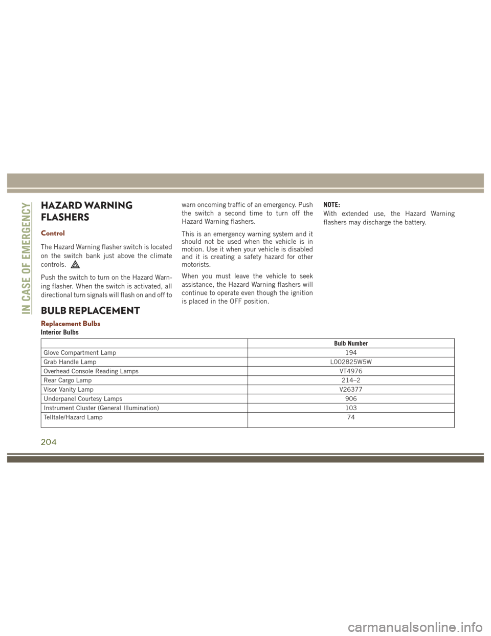
HAZARD WARNING
FLASHERS
Control
The Hazard Warning flasher switch is located
on the switch bank just above the climate
controls.
Push the switch to turn on the Hazard Warn-
ing flasher. When the switch is activated, all
directional turn signals will flash on and off towarn oncoming traffic of an emergency. Push
the switch a second time to turn off the
Hazard Warning flashers.
This is an emergency warning system and it
should not be used when the vehicle is in
motion. Use it when your vehicle is disabled
and it is creating a safety hazard for other
motorists.
When you must leave the vehicle to seek
assistance, the Hazard Warning flashers will
continue to operate even though the ignition
is placed in the OFF position. NOTE:
With extended use, the Hazard Warning
flashers may discharge the battery.
BULB REPLACEMENT
Replacement Bulbs
Interior Bulbs
Bulb Number
Glove Compartment Lamp 194
Grab Handle Lamp L002825W5W
Overhead Console Reading Lamps VT4976
Rear Cargo Lamp 214–2
Visor Vanity Lamp V26377
Underpanel Courtesy Lamps 906
Instrument Cluster (General Illumination) 103
Telltale/Hazard Lamp 74
IN CASE OF EMERGENCY
204
Page 208 of 372
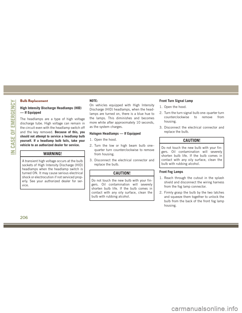
Bulb Replacement
High Intensity Discharge Headlamps (HID)
—
If Equipped
The headlamps are a type of high voltage
discharge tube. High voltage can remain in
the circuit even with the headlamp switch off
and the key removed. Because of this, you
should not attempt to service a headlamp bulb
yourself. If a headlamp bulb fails, take your
vehicle to an authorized dealer for service.
WARNING!
A transient high voltage occurs at the bulb
sockets of High Intensity Discharge (HID)
headlamps when the headlamp switch is
turned ON. It may cause serious electrical
shock or electrocution if not serviced prop-
erly. See your authorized dealer for ser-
vice. NOTE:
On vehicles equipped with High Intensity
Discharge (HID) headlamps, when the head-
lamps are turned on, there is a blue hue to
the lamps. This diminishes and becomes
more white after approximately 10 seconds,
as the system charges.
Halogen Headlamps — If Equipped
1. Open the hood.
2. Turn the low or high beam bulb one–
quarter turn counterclockwise to remove
from housing.
3. Disconnect the electrical connector and replace the bulb.
CAUTION!
Do not touch the new bulb with your fin-
gers. Oil contamination will severely
shorten bulb life. If the bulb comes in
contact with any oily surface, clean the
bulb with rubbing alcohol.
Front Turn Signal Lamp
1. Open the hood.
2. Turn the turn signal bulb one–quarter turncounterclockwise to remove from
housing.
3. Disconnect the electrical connector and replace the bulb.
CAUTION!
Do not touch the new bulb with your fin-
gers. Oil contamination will severely
shorten bulb life. If the bulb comes in
contact with any oily surface, clean the
bulb with rubbing alcohol.
Front Fog Lamps
1. Reach through the cutout in the splashshield and disconnect the wiring harness
from the fog lamp connector.
2. Firmly grasp the bulb by the two latches and squeeze them together to unlock the
bulb from the back of the front fog lamp
housing.
IN CASE OF EMERGENCY
206