ECO mode JEEP GRAND CHEROKEE 2023 Service Manual
[x] Cancel search | Manufacturer: JEEP, Model Year: 2023, Model line: GRAND CHEROKEE, Model: JEEP GRAND CHEROKEE 2023Pages: 424, PDF Size: 15.48 MB
Page 147 of 424
STARTING AND OPERATING145
NOTE:
Keeping your foot on the accelerator pedal can
cause the vehicle to continue to accelerate
beyond the set speed. If this occurs, the
message “DRIVER OVERRIDE” will display in the
instrument cluster display.
If you continue to accelerate beyond the set
speed while ACC is enabled, the system will not
be controlling the distance between your vehicle
and the vehicle ahead. The vehicle speed will
only be determined by the position of the accel-
erator pedal.
To Cancel
The following conditions cancel the ACC or Fixed
Speed Cruise Control systems:
The brake pedal is applied
The CANC (cancel) button is pushed
The gear selector is removed from the DRIVE
position
The Electronic Stability Control/Traction Control
System (ESC/TCS) activates
The vehicle parking brake is applied
The Trailer Sway Control (TSC) activates
The braking temperature exceeds normal range
(overheated) The following conditions will only cancel the ACC
system:
Driver seat belt is unbuckled at low speeds
Driver door is opened at low speeds
To Turn Off
The system will turn off and erase the set speed in
memory if:
The Adaptive Cruise Control (ACC) on/off button
is pushed
Fixed Speed Cruise Control on/off button is
pushed
The ignition is placed in the OFF position
4WD Low is engaged
The Active Driving Assist (ADA) system (if
equipped) is enabled/engaged and the ADA
button is pressed
NOTE:If ADA is not enabled/engaged and the ADA button
is pressed, the ACC system will remain on or turn
on, depending on the state of ACC at the time of
the ADA button press.
To Resume
If there is a set speed in memory, push the RES
(resume) button and remove your foot from the
accelerator pedal. The instrument cluster display
will show the last set speed. Resume can be used at any speed above 20 mph
(32 km/h) when only Fixed Speed Cruise Control is
being used.
Resume can be used at any speed above 0 mph
(0 km/h) when ACC is active.
NOTE:
While in ACC mode, when the vehicle comes to
a complete stop longer than two seconds, the
driver will either have to push the RES (resume)
button or press the accelerator pedal to reen
-
gage the ACC system.
ACC cannot be resumed if there is a stationary
vehicle in front of your vehicle in close proximity.
WARNING!
The Resume function should only be used if
traffic and road conditions permit. Resuming a
set speed that is too high or too low for
prevailing traffic and road conditions could
cause the vehicle to accelerate or decelerate too
sharply for safe operation. Failure to follow these
warnings can result in a collision and death or
serious personal injury.
4
23_WL_OM_EN_USC_t.book Page 145
Page 148 of 424
146STARTING AND OPERATING
To Vary The Speed Setting
To Increase Or Decrease The Set Speed
After setting a speed, you can increase the set
speed by pushing the SET (+) button, or decrease
speed by pushing the SET (-) button.
U.S. Speed (mph)
Pushing the SET (+) , or SET (-) button once will
result in a 1 mph speed adjustment. Each
subsequent tap of the button results in an
adjustment of 1 mph.
If the button is continually pushed, the set
speed will continue to adjust in 5 mph incre -
ments until the button is released. The new set
speed is reflected in the instrument cluster
display.
Metric Speed (km/h)
Pushing the SET (+) , or SET (-) button once will
result in a 1 km/h speed adjustment. Each
subsequent tap of the button results in an
adjustment of 1 km/h.
If the button is continually pushed, the set
speed will continue to adjust in 10 km/h incre -
ments until the button is released. The new set
speed is reflected in the instrument cluster
display.
NOTE:When you override and push the SET (+) button or
SET (-) button, the new set speed will be the current
speed of the vehicle.
When ACC Is Active
When you use the SET (-) button to decelerate, if
the engine’s braking power does not slow the
vehicle sufficiently to reach the set speed, the
brake system will automatically slow the
vehicle.
The ACC system decelerates the vehicle to a full
stop when following the vehicle in front. If your
vehicle follows the vehicle in front to a standstill,
after two seconds the driver will either have to
push the RES (resume) button, or apply the
accelerator pedal to reengage the ACC to the
existing set speed.
The ACC system maintains set speed when
driving uphill and downhill. However, a slight
speed change on moderate hills is normal. In
addition, downshifting may occur while climbing
uphill or descending downhill. This is normal
operation and necessary to maintain set speed.
When driving uphill and downhill, the ACC
system will cancel if the braking temperature
exceeds normal range (overheated).
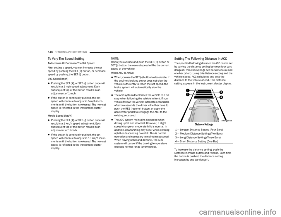
Setting The Following Distance In ACC
The specified following distance for ACC can be set
by varying the distance setting between four bars
(longest), three bars (long), two bars (medium) and
one bar (short). Using this distance setting and the
vehicle speed, ACC calculates and sets the
distance to the vehicle ahead. This distance
setting appears in the instrument cluster display.
Distance Settings
To increase the distance setting, push the
Distance Increase button and release. Each time
the button is pushed, the distance setting
increases by one bar (longer). 1 — Longest Distance Setting (Four Bars)
2 — Medium Distance Setting (Two Bars)
3 — Long Distance Setting (Three Bars)
4 — Short Distance Setting (One Bar)
23_WL_OM_EN_USC_t.book Page 146
Page 153 of 424
STARTING AND OPERATING151
TRAFFIC SIGN ASSIST SYSTEM —
IF EQUIPPED
The Traffic Sign Assist (TSA) system uses a camera
mounted on the windshield, as well as map data
when the vehicle is equipped with Navigation, to
detect recognizable road signs such as:
Speed limits
School zones
No passing zones
NOTE:
The TSA system will automatically display the
detected road sign using the unit of measure-
ment (mph or km/h) selected within the instru -
ment cluster display.
If no speed limit signs are detected, the system
will revert to the speed limit signs that are
stored in the Navigation system.
The system always checks the traffic signs indi -
cating the current speed limit. The system is
able to recognize and display up to two different
road signs in the instrument cluster display.
These road signs can be found on the Driver
Assist page.
ACTIVATION/DEACTIVATION
The TSA System can be enabled/disabled within
the Uconnect system through the Safety/Driver
Assistance menu. System ON is signaled by road
signs shown on the instrument cluster display.
NOTE:Even if the system is OFF, the speed limit sign will
be displayed when the driver selects it on the
HOME screen.
TRAFFIC SIGN ASSIST MODES
TSA has three selectable modes of operation that
are available through the Uconnect system
Ú page 204.
Visual
When Visual is selected, the system will alert the
driver when the current speed of the vehicle
exceeds the detected speed limit by showing a
graphic in the instrument cluster display. Visual + Chime
When Visual + Chime is selected, the system will
alert the driver when the current speed of the
vehicle exceeds the detected speed limit by
showing a graphic in the instrument cluster
display, and by sounding an audible alert. The
audible alert will last for 10 seconds, and the
visual alert will remain on as long as the vehicle is
exceeding the speed limit.
TSA Off
When the TSA system is turned off, the system will
not show any traffic signs (unless selected in the
HOME screen, which will show detected speed
limit signs), and no alerts will be issued to the
driver.
INDICATIONS ON THE DISPLAY
Detected traffic signs are shown in the instrument
cluster display, and can display any combination of
signs at one time (e.g. speed limit, speed limit and
supplemental info, and “Do Not Pass” signs)
depending on what information is available.
When a newly detected speed limit is higher than
the current speed limit, the display will update
along with an up arrow.
4
23_WL_OM_EN_USC_t.book Page 151
Page 155 of 424
STARTING AND OPERATING153
The driver can override ADA at any time by
braking, accelerating, or steering the vehicle.
Just like ACC, ADA will maintain a set speed as long
as the set distance between your vehicle and the
vehicle in front is maintained. ADA will also keep
your vehicle centered between the lane lines, and
monitor for other vehicles in adjacent lanes by
utilizing the Blind Spot Monitoring sensors.
Two types of Active Driving Assist systems are
available:
Base ADA system
Hands-Free ADA system
Base Active Driving Assist System — If Equipped
The Base ADA system uses sensors within the
steering wheel to measure driver attentiveness,
and requires that the driver have their hands on
the steering wheel at all times.
The system will generally aim to keep the vehicle
centered in the lane, but when the driver turns the
steering wheel (e.g. to move farther away from a
large vehicle in an adjacent lane) the system will
reduce its control and enter "co-steering" mode.
While in co-steering mode, the system will provide
reduced assistance and allow the driver to control
the path of the vehicle. Once the driver stops
providing input to the steering wheel, the system
will require a few seconds to fully resume lane
centering assistance, especially during curves. Hands-Free Active Driving Assist System —
If Equipped
The Hands-Free ADA system uses sensors within
the steering wheel and a driver monitoring camera
located on top of the steering column to monitor
driver attentiveness. The Hands-Free ADA system
allows the driver to remove their hands from the
steering wheel when engaged, but requires that
the driver continue to pay attention to the road.
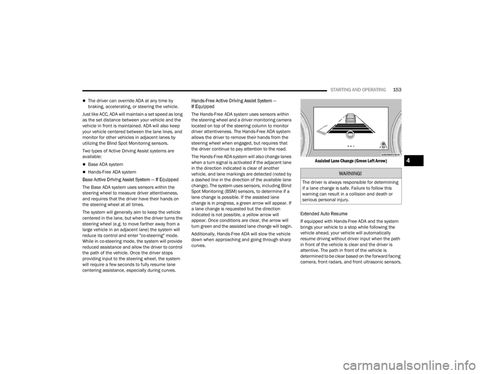
The Hands-Free ADA system will also change lanes
when a turn signal is activated if the adjacent lane
in the direction indicated is clear of another
vehicle, and lane markings are detected (noted by
a dashed line in the direction of the available lane
change). The system uses sensors, including Blind
Spot Monitoring (BSM) sensors, to determine if a
lane change is possible. If the assisted lane
change is in progress, a green arrow will appear. If
a lane change is requested but the direction
indicated is not possible, a yellow arrow will
appear. Once conditions are clear, the arrow will
turn green and the assisted lane change will begin.
Additionally, Hands-Free ADA will slow the vehicle
down when approaching and going through sharp
curves.
Assisted Lane Change (Green Left Arrow)
Extended Auto Resume
If equipped with Hands-Free ADA and the system
brings your vehicle to a stop while following the
vehicle ahead, your vehicle will automatically
resume driving without driver input when the path
in front of the vehicle is clear and the driver is
attentive. The path in front of the vehicle is
determined to be clear based on the forward facing
camera, front radars, and front ultrasonic sensors.WARNING!
The driver is always responsible for determining
if a lane change is safe. Failure to follow this
warning can result in a collision and death or
serious personal injury.
4
23_WL_OM_EN_USC_t.book Page 153
Page 176 of 424
174STARTING AND OPERATING
NOTE:
The Active Lane Management system operates
with similar behavior for a right lane departure.
If the turn signal is activated, and the vehicle
begins to depart the lane at the same time the
Blind Spot Monitoring (BSM) system detects
another vehicle in the BSM zones, the system
will provide a haptic steering wheel vibration
and/or steering assist torque (if programmed in
Uconnect Settings).
CHANGING ACTIVE LANE MANAGEMENT
S
TATUS
Configurable settings for the Active Lane
Management system are available within the
Uconnect system Ú page 204.
Selectable Warning Types:
Vibration Only
Steering Assist Only
Vibration And Steering Assist
Other configurable settings for this system are for
the intensity of the vibration (high/med/low),
steering assist warning (hi/med/low), and the
warning zone sensitivity (early/medium/late).
NOTE:
The system will not apply vibration and/or
steering assist to the steering wheel whenever a
safety system engages (Anti-Lock Brakes, Trac -
tion Control System, Electronic Stability Control,
Forward Collision Warning, etc.).
The Blind Spot Monitoring system will be forced
on when the ALM system is enabled.
The ALM system will be suppressed when the
Active Driving Assist system (if equipped) is
engaged.
PARKVIEW REAR BACK UP CAMERA
Your vehicle is equipped with the ParkView Rear
Back Up Camera that allows you to see an
on-screen image of the rear surroundings of your
vehicle whenever the gear selector is put into
REVERSE. The image will be displayed on the
Uconnect display screen along with a caution note
to “Check Entire Surroundings” across the top of
the screen. After five seconds this note will
disappear. The ParkView camera is located on the
rear of the vehicle above the rear license plate.
When the vehicle is shifted out of REVERSE with
camera delay turned off, the rear camera mode is
exited and the previous screen appears. Manual Activation Of The Back Up Camera
1. Press the Vehicle button located on the
bottom of the Uconnect display and then
select the Controls menu.
2. Press the Back Up Camera icon to turn the Rear View Camera system on.
NOTE:The ParkView Rear Back Up Camera has program -
mable modes of operation that may be selected
through the Uconnect system Ú page 204.
When the vehicle is shifted out of REVERSE with
camera delay turned off, the rear camera mode is
exited and the previous screen appears. When the
vehicle is shifted out of REVERSE with camera delay
turned on, the camera image will continue to be
displayed for up to 10 seconds unless the following
conditions occur: the vehicle speed exceeds 8 mph
(13 km/h), the vehicle is shifted into PARK, the
vehicle’s ignition is placed in the OFF position, or the
touchscreen X button to disable the display of the
Rear View Camera is pressed.
When enabled, active guidelines are overlaid on
the image to illustrate the width of the vehicle and
its projected backup path based on the steering
wheel position. A dashed center line overlay
indicates the center of the vehicle to assist with
parking or aligning to a hitch/receiver. Different
colored zones indicate the distance to the rear of
the vehicle.
23_WL_OM_EN_USC_t.book Page 174
Page 178 of 424
176STARTING AND OPERATING
NOTE:
If the vehicle is in DRIVE, NEUTRAL, or REVERSE,
and speed is greater than or equal to 8 mph
(13 km/h), Zoom View is unavailable and the
icon will appear gray.
While in Zoom View, the guidelines will not be
visible.
VIEWING AT SPEED
When the vehicle is in PARK, NEUTRAL or
DRIVE, the Rear View Camera can be
activated with the Back Up Camera
button in the Controls menu. This feature
allows the customer to monitor the area directly
behind the vehicle (or trailer, if equipped) for up to
10 seconds while driving. If the vehicle speed
remains below 8 mph (13 km/h), the Rear View
Camera image will be displayed continuously until
deactivated via the X button on the touchscreen.
TRAILCAM SYSTEM — IF EQUIPPED
The TrailCam system allows you to you see an
on-screen image of the front view of your vehicle.
The image will be displayed on the Uconnect
display along with a caution note “Check Entire
Surroundings” across the top of the screen.
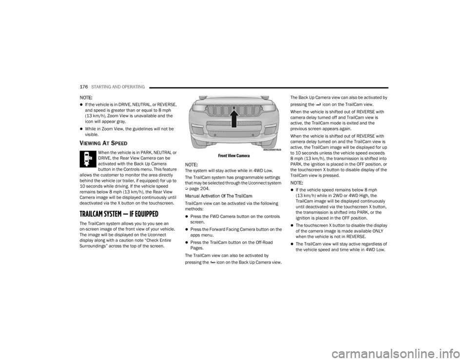
Front View Camera
NOTE:The system will stay active while in 4WD Low.
The TrailCam system has programmable settings
that may be selected through the Uconnect system
Ú
page 204.
Manual Activation Of The TrailCam
TrailCam view can be activated via the following
methods:
Press the FWD Camera button on the controls
screen.
Press the Forward Facing Camera button on the
apps menu.
Press the TrailCam button on the Off-Road
Pages.
The TrailCam view can also be activated by
pressing the icon on the Back Up Camera view. The Back Up Camera view can also be activated by
pressing the icon on the TrailCam view.
When the vehicle is shifted out of REVERSE with
camera delay turned off and TrailCam view is
active, the TrailCam mode is exited and the
previous screen appears again.
When the vehicle is shifted out of REVERSE with
camera delay turned on and the TrailCam view is
active, the TrailCam image will be displayed for up
to 10 seconds unless the vehicle speed exceeds
8 mph (13 km/h), the transmission is shifted into
PARK, the ignition is placed in the OFF position, or
the touchscreen X button to disable display of the
TrailCam view is pressed.
NOTE:
If the vehicle speed remains below 8 mph
(13 km/h) while in 2WD or 4WD High, the
TrailCam image will be displayed continuously
until deactivated via the touchscreen X button,
the transmission is shifted into PARK, or the
ignition is placed in the OFF position.
The touchscreen X button to disable the display
of the camera image is made available ONLY
when the vehicle is not in REVERSE.
The TrailCam view will stay active regardless of
the vehicle speed and time while in 4WD Low.
23_WL_OM_EN_USC_t.book Page 176
Page 183 of 424
STARTING AND OPERATING181
SURROUND VIEW CAMERA SYSTEM —
IF EQUIPPED
Your vehicle may be equipped with the Surround
View Camera system that allows you to see an
on-screen image of the surroundings and Top View
of your vehicle whenever the gear selector is put
into REVERSE or a different view is selected
through the touchscreen buttons. The Top View of
the vehicle will show which doors are open. The
image will be displayed on the Uconnect display
along with a caution note “Check Entire
Surroundings” across the top of the screen. After
five seconds, this note will disappear. The
Surround View Camera system is comprised of four
sequential cameras located in the front grille, rear
liftgate and side mirrors.
NOTE:The Surround View Camera system has program -
mable settings that may be selected through the
Uconnect system Ú page 204.
Press this button on the touchscreen to
enter the Surround View Camera menu in
the Uconnect system.
When the vehicle is shifted into REVERSE, the Rear
View or Top View is the default view of the system. When the vehicle is shifted out of REVERSE with
camera delay turned on, the camera image will
continue to be displayed for up to 10 seconds
unless the vehicle speed exceeds 8 mph
(13 km/h), the vehicle is shifted into PARK or the
ignition is placed in the OFF position. There is a
touchscreen X button to disable the display of the
camera image.
When the vehicle is shifted out of REVERSE with
camera delay turned off, the Surround View
Camera mode is exited and the last known screen
appears again.
When enabled, active guidelines are overlaid on
the image to illustrate the width of the vehicle,
including the side view mirrors and its projected
backup path based on the steering wheel position.
Different colored zones indicate the distance to
the rear of the vehicle.
The following table shows the approximate
distances for each zone:
Modes Of Operation
Manual activation of the Surround View Camera is
selected by pressing the Surround View Camera
button located in the Controls menu within the
Uconnect system.
Top View
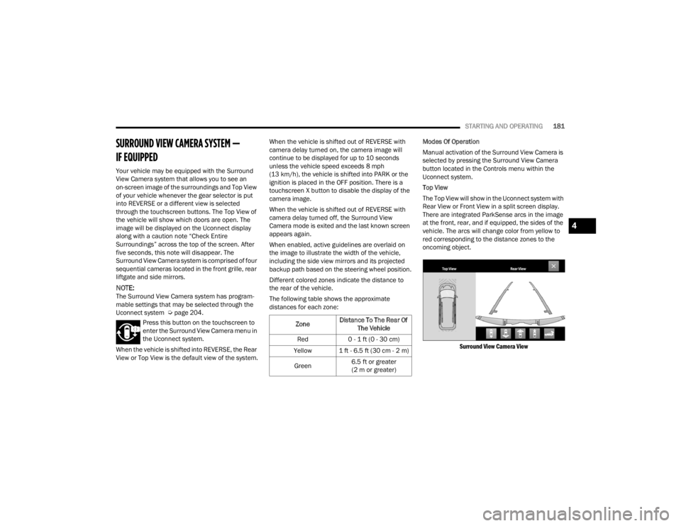
The Top View will show in the Uconnect system with
Rear View or Front View in a split screen display.
There are integrated ParkSense arcs in the image
at the front, rear, and if equipped, the sides of the
vehicle. The arcs will change color from yellow to
red corresponding to the distance zones to the
oncoming object.
Surround View Camera View
Zone Distance To The Rear Of
The Vehicle
Red 0 - 1 ft (0 - 30 cm)
Yellow 1 ft - 6.5 ft (30 cm - 2 m)
Green 6.5 ft or greater
(2 m or greater)
4
23_WL_OM_EN_USC_t.book Page 181
Page 189 of 424
STARTING AND OPERATING187
RECOMMENDED DISTRIBUTION HITCH
ADJUSTMENT
1. Verify that the vehicle is at the Normal Ride
Height.
NOTE:The vehicle must remain in the engine run position
with all doors closed while attaching a trailer for
proper leveling of the air suspension system.
2. Position the vehicle to be ready to connect to the trailer (do not connect the trailer). 3. For vehicles equipped with Quadra-Lift air
suspension, use the touchscreen radio
settings to enable Tire/Jack mode. Tire/Jack
mode will be canceled and the procedure must
be restarted if the vehicle is driven at speeds
above 5mph (8 km/h).
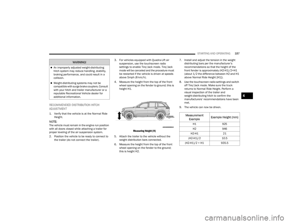
4. Measure the height from the top of the front wheel opening on the fender to ground; this is
height H1.
Measuring Height (H)
5. Attach the trailer to the vehicle without the weight distribution bars connected.
6. Measure the height from the top of the front wheel opening on the fender to the ground;
this is height H2. 7. Install and adjust the tension in the weight
distributing bars per the manufacturer’s
recommendations so that the height of the
front fender is approximately (H2-H1)/2+H1
(about 1/2 the difference between H2 and H1
above Normal Ride Height [H1]).
8. Use the touchscreen radio settings and switch off Tire/Jack mode. Make sure the truck
returns to Normal Ride Height. Perform a
visual inspection of the trailer and
weight-distributing hitch to confirm the
manufacturers’ recommendations have been
met.
9. The vehicle can now be driven.
An improperly adjusted weight-distributing
hitch system may reduce handling, stability,
braking performance, and could result in a
collision.
Weight-distributing systems may not be
compatible with surge brake couplers. Consult
with your hitch and trailer manufacturer or a
reputable Recreational Vehicle dealer for
additional information.
WARNING!
Measurement Example Example Height (mm)
H1
925
H2 946
H2-H1 21
(H2-H1)/2 10.5
(H2-H1)/2 + H1 935.5
4
23_WL_OM_EN_USC_t.book Page 187
Page 198 of 424
196STARTING AND OPERATING
RECREATIONAL TOWING — TWO-WHEEL
D
RIVE MODELS
DO NOT flat tow this vehicle. Damage to the
drivetrain will result.
Recreational towing (for two-wheel drive models) is
allowed ONLY if the rear wheels are OFF the
ground. This may be accomplished using a tow
dolly or vehicle trailer. If using a tow dolly, follow
this procedure:
1. Properly secure the dolly to the tow vehicle,
following the dolly manufacturer's
instructions.
2. Drive the rear wheels onto the tow dolly.
3. Apply the Electric Park Brake. Shift the transmission into PARK.
4. Turn the ignition OFF.
5. Properly secure the rear wheels to the dolly, following the dolly manufacturer’s
instructions.
6. Install a suitable clamping device, designed for towing, to secure the front wheels in the
straight position.
RECREATIONAL TOWING —
Q
UADRA-TRAC I (SINGLE-SPEED
T
RANSFER CASE WITHOUT 4WD LOW
R
ANGE) FOUR-WHEEL DRIVE MODELS
Recreational towing is not allowed. These models
do not have a N (NEUTRAL) position in the transfer
case.
NOTE:This vehicle may be towed on a flatbed or vehicle
trailer provided all four wheels are OFF the ground.
RECREATIONAL TOWING —
Q
UADRA–TRAC II WITH 4WD LOW
R
ANGE
The transfer case must be shifted into N
(NEUTRAL) and the transmission must be in PARK
(P) for recreational towing. The N (NEUTRAL)
selection button is adjacent to the air suspension
switch. Shifts into and out of transfer case N
(NEUTRAL) can take place with the selector switch
in any mode position.
NOTE:
Ensure vehicle is set to Normal Ride Height - if
equipped Ú page 136.
If the vehicle is equipped with Quadra-Lift air
suspension, the engine should be started and
left running for a minimum of 60 seconds (with
all the doors closed) at least once every 24
hours. This process allows the air suspension to
adjust the vehicle’s ride height to compensate
for temperature effects.
CAUTION!
Towing with the rear wheels on the ground will
cause severe transmission damage. Damage
from improper towing is not covered under the
New Vehicle Limited Warranty.
CAUTION!
Towing this vehicle in violation of the above
requirements can cause severe transmission
and/or transfer case damage. Damage from
improper towing is not covered under the New
Vehicle Limited Warranty.
23_WL_OM_EN_USC_t.book Page 196
Page 200 of 424
198STARTING AND OPERATING
If the vehicle is equipped with Quadra-Lift
air suspension, the engine should be
started and left running for a minimum of
60 seconds (with all the doors closed) at
least once every 24 hours. This process
allows the air suspension to adjust the
vehicle’s ride height to compensate for
temperature effects.
Engaging/disengaging of the Electric Park
Brake requires the ignition to be in the ON/
RUN position.
If shift conditions/interlocks are not met, a
“4WD Shift Canceled” or a “4WD Shift
Aborted/ Retry Shift” message will be
displayed on the instrument cluster. To reat -
tempt shift, put the transmission in
NEUTRAL (N) and push and hold the 4WD
LOW button.
If shift conditions/interlocks are not met, a
“To Complete 4WD Shift Put Transmission
In Neutral” or a “To Complete 4WD Shift
Speed Must Be Below 3 MPH” or a “To
Complete 4WD Shift Allow Engine To Return
To Idle” message will flash from the instru -
ment cluster display Ú page 98.
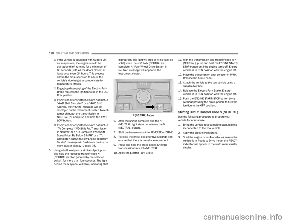
5. Using a ballpoint pen or similar object, push and hold the recessed transfer case N
(NEUTRAL) button (located by the selector
switch) for more than four seconds. The light
behind the N symbol will blink, indicating shift in progress. The light will stop blinking (stay on
solid) when the shift to N (NEUTRAL) is
complete. A “Four Wheel Drive System In
Neutral” message will appear in the
instrument cluster.
N (NEUTRAL) Button
6. After the shift is complete and the N (NEUTRAL) light stays on, release the N
(NEUTRAL) button.
7. Shift the transmission into REVERSE or DRIVE.
8. Release the brake pedal for five seconds and ensure that there is no vehicle movement.
9. Press and hold the brake pedal. Shift the transmission back into NEUTRAL.
10. Apply the Electric Park Brake. 11. With the transmission and transfer case in N
(NEUTRAL), push and hold the ENGINE START/
STOP button until the engine turns off. Ensure
vehicle is in RUN position with the engine off.
12. Place the transmission gear selector in PARK. Release the brake pedal.
13. Attach the vehicle to the tow vehicle using a suitable tow bar.
14. Release the Electric Park Brake. Ensure vehicle is in RUN position with the engine off.
15. Push the ENGINE START/STOP button twice (without pressing the brake pedal), to turn the
ignition to the OFF position.
Shifting Out Of Transfer Case N (NEUTRAL)
Use the following procedure to prepare your
vehicle for normal use:
1. Bring the vehicle to a complete stop, leaving it connected to the tow vehicle.
2. Apply the Electric Park Brake.
3. Start the engine or for 4xe vehicles ensure the vehicle is in Ready to Drive mode, the READY
indicator will appear in the instrument cluster
display.
23_WL_OM_EN_USC_t.book Page 198