JEEP WRANGLER 2023 Owners Manual
Manufacturer: JEEP, Model Year: 2023, Model line: WRANGLER, Model: JEEP WRANGLER 2023Pages: 396, PDF Size: 25.15 MB
Page 341 of 396
SERVICING AND MAINTENANCE339
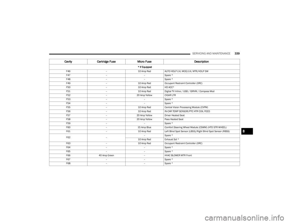
F46 –10 Amp RedAUTO HDLP LVL MOD/LVL MTR/HDLP SW
F47 ––Spare *
F48 ––Spare *
F49 –10 Amp RedOccupant Restraint Controller (ORC)
F50 –10 Amp RedHD ACC*
F51 –10 Amp RedDigital TV Inline / USB / ISRVM / Compass Mod
F52 –20 Amp Yellow CIGAR LTR
F53 ––Spare *
F54 ––Spare *
F55 –10 Amp RedCentral Vision Processing Module (CVPM)
F56 –10 Amp RedIN-CAR TEMP SENSOR/PTC HTR COIL FEED
F57 –20 Amp Yellow Driver Heated Seat
F58 –20 Amp Yellow Pass Heated Seat
F59 ––Spare *
F60 –15 Amp BlueComfort Steering Wheel Module (CSWM) (HTD STR WHEEL)
F61 –10 Amp RedLeft Blind Spot Sensor (LBSS)/Right Blind Spot Sensor (RBSS)
F62 ––
Spare *
10 Amp Red Exhaust Sol *
F63 –10 Amp RedOccupant Restraint Controller (ORC)
F64 ––Spare *
F65 ––Spare *
F66 40 Amp Green –HVAC BLOWER MTR Front
F67 ––Spare *
F68 ––Spare *
Cavity Cartridge Fuse Micro Fuse Description
* If Equipped
8
23_JL_OM_EN_USC_t.book Page 339
Page 342 of 396
340SERVICING AND MAINTENANCE
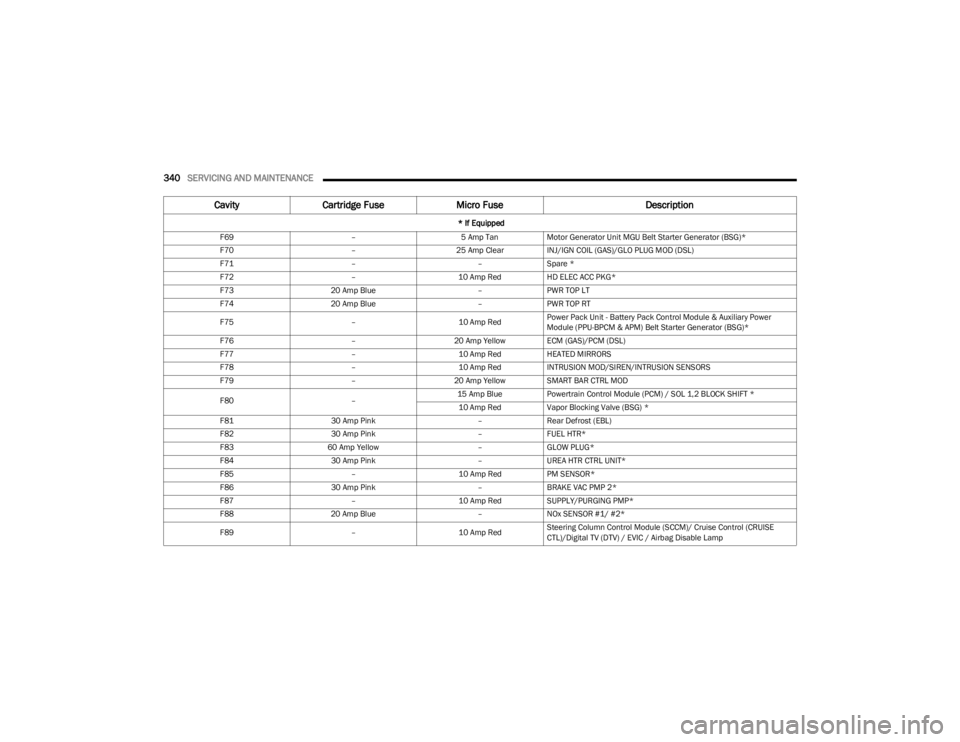
F69 –5 Amp TanMotor Generator Unit MGU Belt Starter Generator (BSG)*
F70 –25 Amp ClearINJ/IGN COIL (GAS)/GLO PLUG MOD (DSL)
F71 ––Spare *
F72 –10 Amp RedHD ELEC ACC PKG*
F73 20 Amp Blue –PWR TOP LT
F74 20 Amp Blue –PWR TOP RT
F75 –10 Amp RedPower Pack Unit - Battery Pack Control Module & Auxiliary Power
Module (PPU-BPCM & APM) Belt Starter Generator (BSG)*
F76 –20 Amp Yellow ECM (GAS)/PCM (DSL)
F77 –10 Amp RedHEATED MIRRORS
F78 –10 Amp RedINTRUSION MOD/SIREN/INTRUSION SENSORS
F79 –20 Amp Yellow SMART BAR CTRL MOD
F80 –15 Amp Blue
Powertrain Control Module (PCM) / SOL 1,2 BLOCK SHIFT *
10 Amp Red Vapor Blocking Valve (BSG) *
F81 30 Amp Pink –Rear Defrost (EBL)
F82 30 Amp Pink –FUEL HTR*
F83 60 Amp Yellow –GLOW PLUG*
F84 30 Amp Pink –UREA HTR CTRL UNIT*
F85 –10 Amp RedPM SENSOR*
F86 30 Amp Pink –BRAKE VAC PMP 2*
F87 –10 Amp RedSUPPLY/PURGING PMP*
F88 20 Amp Blue –NOx SENSOR #1/ #2*
F89 –10 Amp RedSteering Column Control Module (SCCM)/ Cruise Control (CRUISE
CTL)/Digital TV (DTV) / EVIC / Airbag Disable Lamp
Cavity
Cartridge Fuse Micro Fuse Description
* If Equipped
23_JL_OM_EN_USC_t.book Page 340
Page 343 of 396
SERVICING AND MAINTENANCE341
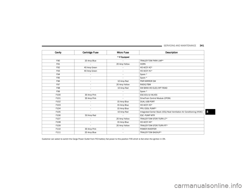
Customer can select to switch the Cargo Power Outlet from F43 battery fed power to this position F45 which is fed when the ignition in ON.F90
20 Amp Blue –TRAILER TOW PARK LMP*
F91 –20 Amp Yellow HORN
F92 40 Amp Green –HD ACCY #2*
F93 40 Amp Green –HD ACCY #1*
F94 ––Spare *
F95 ––Spare *
F96 –10 Amp RedPWR MIRROR SW
F97 –20 Amp Yellow RADIO/TBM
F98 –10 Amp RedSW BANK-HD ELEC/OFF ROAD
F99 ––Spare *
F100 30 Amp Pink –ESC-ECU & VALVES
F101 30 Amp Pink –DriveTrain Control Module (DTCM)
F102 –15 Amp BlueDUAL USB PORT
F103 –15 Amp BlueHD ACCY #3*
F104 –15 Amp BluePPU COOL PUMP*
F105 –10 Amp RedIntegrated Center Stack (ICS)/Heat Ventilation Air Conditioning (HVAC)
F106 50 Amp Red –ESC -PUMP MTR
F107 –20 Amp Yellow TRAILER TOW STOP/TURN LT*
F108 –15 Amp BlueHD ACCY #4*
F109 –20 Amp Yellow TRAILER TOW STOP/TURN RT*
F110 30 Amp Pink –POWER INVERTER
F111 20 Amp Blue –TRAILER TOW BACKUP*
Cavity Cartridge Fuse Micro Fuse Description
* If Equipped
8
23_JL_OM_EN_USC_t.book Page 341
Page 344 of 396
342SERVICING AND MAINTENANCE
BULB REPLACEMENT
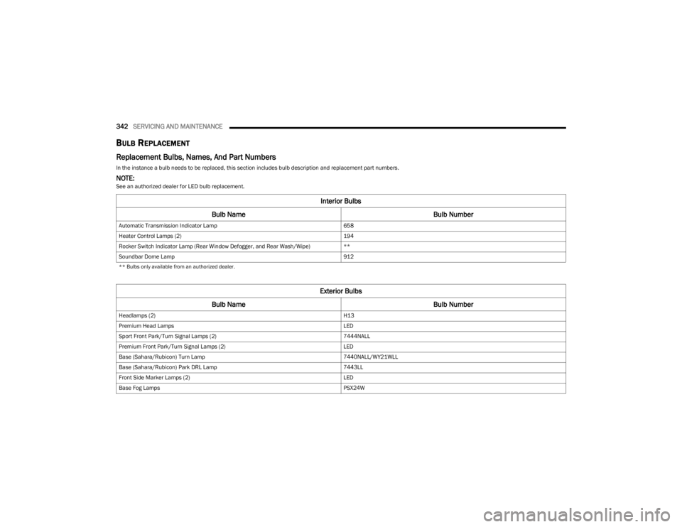
Replacement Bulbs, Names, And Part Numbers
In the instance a bulb needs to be replaced, this section includes bulb description and replacement part numbers.
NOTE:See an authorized dealer for LED bulb replacement.
Interior Bulbs
Bulb Name Bulb Number
Automatic Transmission Indicator Lamp 658
Heater Control Lamps (2) 194
Rocker Switch Indicator Lamp (Rear Window Defogger, and Rear Wash/Wipe) **
Soundbar Dome Lamp 912
** Bulbs only available from an authorized dealer.
Exterior Bulbs
Bulb Name Bulb Number
Headlamps (2) H13
Premium Head Lamps LED
Sport Front Park/Turn Signal Lamps (2) 7444NALL
Premium Front Park/Turn Signal Lamps (2) LED
Base (Sahara/Rubicon) Turn Lamp 7440NALL/WY21WLL
Base (Sahara/Rubicon) Park DRL Lamp 7443LL
Front Side Marker Lamps (2) LED
Base Fog Lamps PSX24W
23_JL_OM_EN_USC_t.book Page 342
Page 345 of 396
SERVICING AND MAINTENANCE343
Bulb Replacement
NOTE:Lens fogging can occur under certain atmospheric condi -
tions. This will usually clear as atmospheric conditions
change to allow the condensation to change back into a
vapor. Turning the lamps on will usually accelerate the
clearing process.
HALOGEN HEADLAMPS
See the following steps to replace:
1. Open hood and support using prop rod.
2. Remove the front grille. Turn the retainers along the top a quarter turn counterclockwise and remove. 3. Pull the bottom of the grille away starting at one side
and working toward the other.
4. Remove the three screws holding the headlamp to the vehicle.
5. Remove lamp from the vehicle.
6. Remove the lamp from the collar.
7. Grab the bulb and rotate a quarter turn counter -
clockwise.
8. Pull the bulb from the housing.
9. Push connector locking tab to the unlock position.
10. Remove connector from bulb.
11. Push connector onto new bulb base, and push the connector locking tab to the lock position. 12. Reinstall bulb housing. Rotate the bulb a quarter turn
clockwise.
Premium Fog Lamps
LED
Rear Premium LED Tail Lamps LED
Rear Base Tail Lamp Stop/Tail/Turn Bulb 3157
Rear Base Tail Lamp Backup Bulb 7440
Rear Base Tail Lamp Side Marker LED
Center High Mounted Stop Lamp (CHMSL) LED
License Lamp LED
NOTE: Numbers refer to commercial bulb types that can be purchased from an authorized dealer. If a bulb needs to be replaced, visit an authorized dealer or refer to the applicable Service
Manual.
Exterior Bulbs
Bulb Name Bulb Number
CAUTION!
Do not touch the new bulb with your fingers. Oil
contamination will severely shorten bulb life. If the bulb
comes in contact with any oily surface, clean the bulb
with rubbing alcohol.
8
23_JL_OM_EN_USC_t.book Page 343
Page 346 of 396
344SERVICING AND MAINTENANCE
FRONT PARK/TURN SIGNAL
See the following steps to replace:
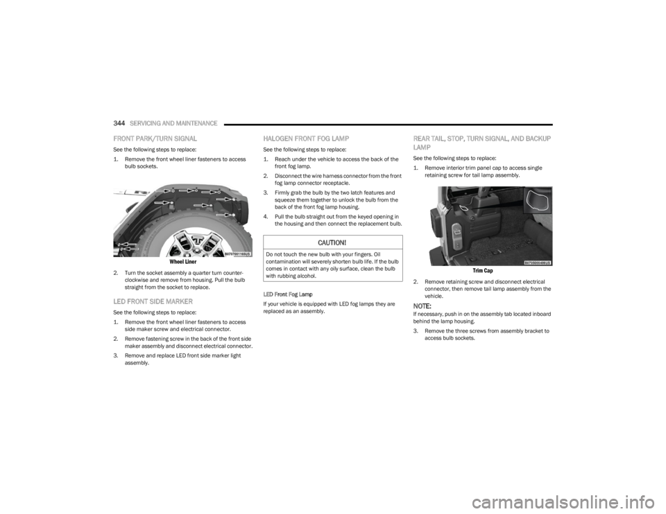
1. Remove the front wheel liner fasteners to access
bulb sockets.
Wheel Liner
2. Turn the socket assembly a quarter turn counter -
clockwise and remove from housing. Pull the bulb
straight from the socket to replace.
LED FRONT SIDE MARKER
See the following steps to replace:
1. Remove the front wheel liner fasteners to access side maker screw and electrical connector.
2. Remove fastening screw in the back of the front side maker assembly and disconnect electrical connector.
3. Remove and replace LED front side marker light assembly.
HALOGEN FRONT FOG LAMP
See the following steps to replace:
1. Reach under the vehicle to access the back of the front fog lamp.
2. Disconnect the wire harness connector from the front fog lamp connector receptacle.
3. Firmly grab the bulb by the two latch features and squeeze them together to unlock the bulb from the
back of the front fog lamp housing.
4. Pull the bulb straight out from the keyed opening in the housing and then connect the replacement bulb.
LED Front Fog Lamp
If your vehicle is equipped with LED fog lamps they are
replaced as an assembly.
REAR TAIL, STOP, TURN SIGNAL, AND BACKUP
LAMP
See the following steps to replace:
1. Remove interior trim panel cap to access single retaining screw for tail lamp assembly.
Trim Cap
2. Remove retaining screw and disconnect electrical connector, then remove tail lamp assembly from the
vehicle.
NOTE:If necessary, push in on the assembly tab located inboard
behind the lamp housing.
3. Remove the three screws from assembly bracket to access bulb sockets.
CAUTION!
Do not touch the new bulb with your fingers. Oil
contamination will severely shorten bulb life. If the bulb
comes in contact with any oily surface, clean the bulb
with rubbing alcohol.
23_JL_OM_EN_USC_t.book Page 344
Page 347 of 396
SERVICING AND MAINTENANCE345
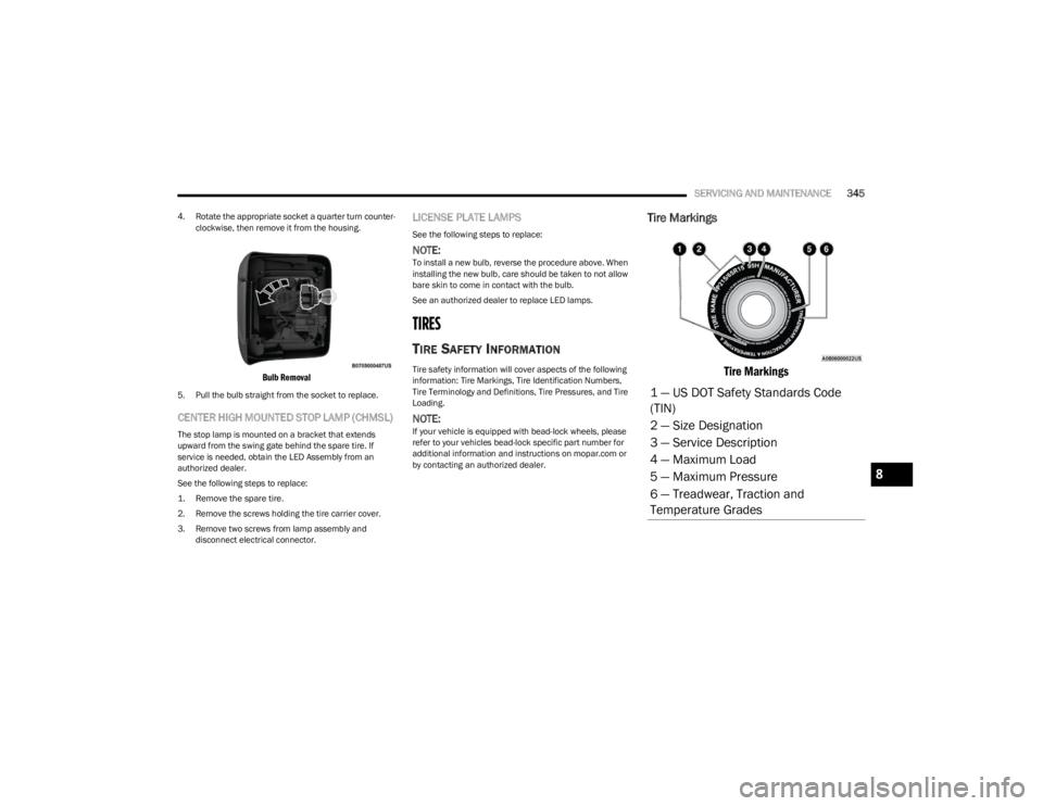
4. Rotate the appropriate socket a quarter turn counter -
clockwise, then remove it from the housing.
Bulb Removal
5. Pull the bulb straight from the socket to replace.
CENTER HIGH MOUNTED STOP LAMP (CHMSL)
The stop lamp is mounted on a bracket that extends
upward from the swing gate behind the spare tire. If
service is needed, obtain the LED Assembly from an
authorized dealer.
See the following steps to replace:
1. Remove the spare tire.
2. Remove the screws holding the tire carrier cover.
3. Remove two screws from lamp assembly and disconnect electrical connector.
LICENSE PLATE LAMPS
See the following steps to replace:
NOTE:To install a new bulb, reverse the procedure above. When
installing the new bulb, care should be taken to not allow
bare skin to come in contact with the bulb.
See an authorized dealer to replace LED lamps.
TIRES
TIRE SAFETY INFORMATION
Tire safety information will cover aspects of the following
information: Tire Markings, Tire Identification Numbers,
Tire Terminology and Definitions, Tire Pressures, and Tire
Loading.
NOTE:If your vehicle is equipped with bead-lock wheels, please
refer to your vehicles bead-lock specific part number for
additional information and instructions on mopar.com or
by contacting an authorized dealer.
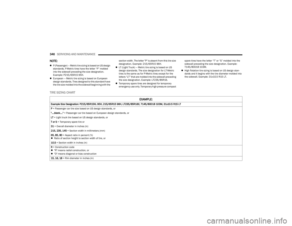
Tire Markings
Tire Markings
1 — US DOT Safety Standards Code
(TIN)
2 — Size Designation
3 — Service Description
4 — Maximum Load
5 — Maximum Pressure
6 — Treadwear, Traction and
Temperature Grades
8
23_JL_OM_EN_USC_t.book Page 345
Page 348 of 396
346SERVICING AND MAINTENANCE
NOTE:
P (Passenger) — Metric tire sizing is based on US design
standards. P-Metric tires have the letter “P” molded
into the sidewall preceding the size designation.
Example: P215/65R15 95H.
European — Metric tire sizing is based on European
design standards. Tires designed to this standard have
the tire size molded into the sidewall beginning with the section width. The letter "P" is absent from this tire size
designation. Example: 215/65R15 96H.
LT (Light Truck) — Metric tire sizing is based on US
design standards. The size designation for LT-Metric
tires is the same as for P-Metric tires except for the
letters “LT” that are molded into the sidewall preceding
the size designation. Example: LT235/85R16.
Temporary spare tires are designed for temporary
emergency use only. Temporary high pressure compact spare tires have the letter “T” or “S” molded into the
sidewall preceding the size designation. Example:
T145/80D18 103M.
High flotation tire sizing is based on US design stan -
dards and it begins with the tire diameter molded into
the sidewall. Example: 31x10.5 R15 LT.
TIRE SIZING CHART
EXAMPLE:
Example Size Designation: P215/65R15XL 95H, 215/65R15 96H, LT235/85R16C, T145/80D18 103M, 31x10.5 R15 LT
P = Passenger car tire size based on US design standards, or
"....blank...." = Passenger car tire based on European design standards, or
LT = Light truck tire based on US design standards, or
T or S = Temporary spare tire or
31 = Overall diameter in inches (in)
215, 235, 145 = Section width in millimeters (mm)
65, 85, 80 = Aspect ratio in percent (%)
Ratio of section height to section width of tire, or
10.5 = Section width in inches (in)
R = Construction code
"R" means radial construction, or
"D" means diagonal or bias construction
15, 16, 18 = Rim diameter in inches (in)
23_JL_OM_EN_USC_t.book Page 346
Page 349 of 396
SERVICING AND MAINTENANCE347
Tire Identification Number (TIN)
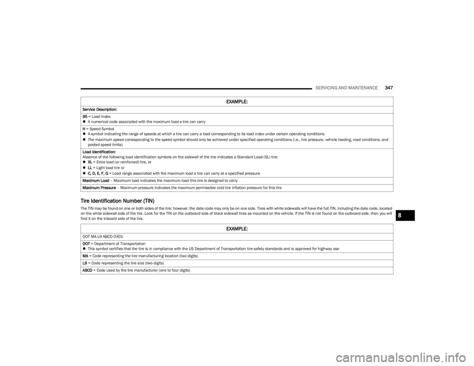
The TIN may be found on one or both sides of the tire; however, the date code may only be on one side. Tires with white sidewalls will have the full TIN, including the date code, located
on the white sidewall side of the tire. Look for the TIN on the outboard side of black sidewall tires as mounted on the vehicle. If the TIN is not found on the outboard side, then you will
find it on the inboard side of the tire.Service Description:
95
= Load Index
A numerical code associated with the maximum load a tire can carry
H = Speed Symbol
A symbol indicating the range of speeds at which a tire can carry a load corresponding to its load index under certain operating conditions
The maximum speed corresponding to the speed symbol should only be achieved under specified operating conditions (i.e., tire pressure, vehicle loading, road conditions, and
posted speed limits)
Load Identification:
Absence of the following load identification symbols on the sidewall of the tire indicates a Standard Load (SL) tire:
XL = Extra load (or reinforced) tire, or
LL = Light load tire or
C, D, E, F, G = Load range associated with the maximum load a tire can carry at a specified pressure
Maximum Load – Maximum load indicates the maximum load this tire is designed to carry
Maximum Pressure – Maximum pressure indicates the maximum permissible cold tire inflation pressure for this tire
EXAMPLE:
EXAMPLE:
DOT MA L9 ABCD 0301
DOT = Department of Transportation
This symbol certifies that the tire is in compliance with the US Department of Transportation tire safety standards and is approved for highway use
MA = Code representing the tire manufacturing location (two digits)
L9 = Code representing the tire size (two digits)
ABCD = Code used by the tire manufacturer (one to four digits)
8
23_JL_OM_EN_USC_t.book Page 347
Page 350 of 396
348SERVICING AND MAINTENANCE
Tire Terminology And Definitions
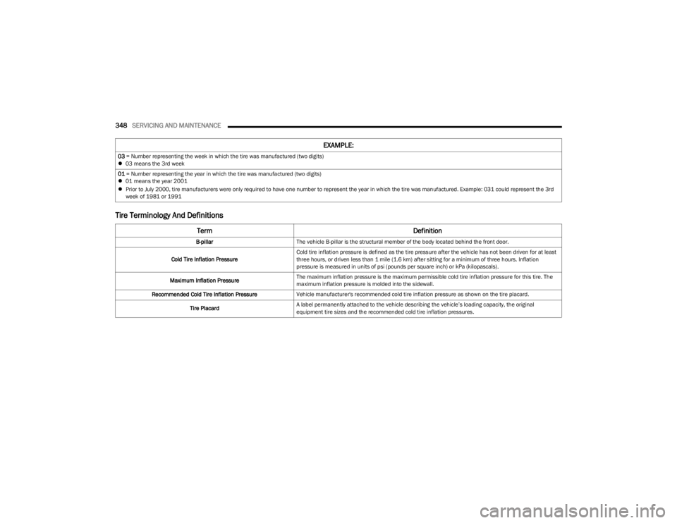
03 = Number representing the week in which the tire was manufactured (two digits)
03 means the 3rd week
01 = Number representing the year in which the tire was manufactured (two digits)
01 means the year 2001
Prior to July 2000, tire manufacturers were only required to have one number to represent the year in which the tire was manufactured. Example: 031 could represent the 3rd
week of 1981 or 1991
Term Definition
B-pillarThe vehicle B-pillar is the structural member of the body located behind the front door.
Cold Tire Inflation Pressure Cold tire inflation pressure is defined as the tire pressure after the vehicle has not been driven for at least
three hours, or driven less than 1 mile (1.6 km) after sitting for a minimum of three hours. Inflation
pressure is measured in units of psi (pounds per square inch) or kPa (kilopascals).
Maximum Inflation Pressure The maximum inflation pressure is the maximum permissible cold tire inflation pressure for this tire. The
maximum inflation pressure is molded into the sidewall.
Recommended Cold Tire Inflation Pressure Vehicle manufacturer's recommended cold tire inflation pressure as shown on the tire placard.
Tire Placard A label permanently attached to the vehicle describing the vehicle’s loading capacity, the original
equipment tire sizes and the recommended cold tire inflation pressures.
EXAMPLE:
23_JL_OM_EN_USC_t.book Page 348