KIA CARNIVAL 2007 Workshop Manual
Manufacturer: KIA, Model Year: 2007, Model line: CARNIVAL, Model: KIA CARNIVAL 2007Pages: 1575, PDF Size: 44.86 MB
Page 1261 of 1575

MEMORY STORAGE OPERATION BY KEYLESS
1.If "ID1" or "ID2" is received during keyless lock operation, record seat and pedal position in keyless code. (there is
no buzzer output during memory storage operation by keyless)
2. Memory storage operation is allowed for a single ID after a change of IG from "on" →"off".
3. Any one of the following conditions will prevent keyless Memory storage operation.
a. When "P" position switch is not on.
b. When Vehicle Speed in CAN BUS data transmitted from CLUSTER is "3km/h" or faster.
c. When seat and pedal is manipulated by CAN BUS and manual switch.
d. When IG transmitted from IPM is other than off.
PRESET RECALL OPERATION BY KEYLESS
1.When IG is off (CAN BUS data IG transmitted from IPM is "off") and a key is removed (CAN BUS data Key
Reminder Switch transmitted from IPM is "off"), and if "ID1" or "ID2" is received during keyless unlock operation, it
automatically adjusts seat and pedal positions as memorized in keyless code (there is no buzzer output during
preset recall operation by keyless). However, seat slide adjustment position is determined as follows, depending on
Auto switch.
a. When auto switch is on ("IMS Auto Switch" is "on") , the position is automatically adjusted to 50 mm farther
back than target position, and if a key is inserted ("Key Reminder Switch" changes from "off" to "on"), it
conducts Get- on gearing operation to a target preset recall position.
b. If auto switch is off ("IMS Auto Switch" is "off"), it moves to the target memory play position.
2. Any one of the following conditions will prevent preset recall operation.
a. When "P" position switch is not on.
b. When Vehicle Speed in CAN BUS data transmitted from cluster is "3km/h" or faster.
c. When seat and pedal is manipulated by CAN BUS and manual switch.
d. When IG Switch transmitted from IPM is other than off.
e. When a key is inserted.
3. Playing will be halted during preset recall operation if any of the following conditions is met.
a. When "P" position switch is not on.
b. When vehicle speed in CAN BUS data transmitted from cluster is "3km/h" or faster.
c. When seat and pedal is manipulated by CAN BUS and manual switch.
SETTING LIMIT
1.A limit switch is installed to prevent the seat from traveling beyond the maximum forward/reward positions.
2. No limit switch is installed for the recline, height, or pedal adjustments. Arbitrary limit positions are used for these
functions.
DETECTING ERRORS FOR SEAT
Take countermeasure against error if the following conditions occur during manual switch operation.
a. Error when pulse is not fed.
SlideReclineFront height Rear height
Page 1262 of 1575

Error conditionBelow 6 pulses in 2 sec. Below 6 pulses in 1 sec.
Prerequisite FR/RR limit SW on Limit setting complete
a. Stop the related motor(seat / pedal) if an error is detected during playing or Easy access function operation.
b. Stop the corresponding motor if an error is detected during manual operation (excluding slide motor).
b. If seat sensor Vcc below 1V is detected by 1s
a. Stop all seat motors running if seat sensor Vcc error is detected during playing or Easy access function operation.
(no buzzer output)
c. Return if seat sensor Vcc is 4V or more.
DETECTING ERRORS FOR ADJUST PEDAL
1.If signal change is below 0.06V per sec though motor is running.
a. Stop the corresponding motor if error is detected during playing or Easy access function operation.
2. If adjust pedal sensor Vcc below 1V is detected by 1s
a. Stop pedal motor running if pedal sensor Vcc error is detected during playing or Easy access function operation.
(no buzzer output)
3. Return if adjust pedal sensor Vcc is 4V or more.
HANDLING ERRORS
1.If errors are discovered, regard them as harness disconnection or sensor failure, and conduct the following
measures.
a. Stop auto control (play or Easy access function operation) if it is under auto control and set off buzzer 10 times
(however, have motors other than the one with an error operate normally).
b. Set off alarm again in case of recurrence of error after restoration of a motor with an error.
c. Complete alarm 10 times though it comes back to normal during error alarm.
d. Stop alarm if receiving memory recall or play order, and set off buzzer in the corresponding function.
e. Manual operation control is allowed even for a motor with errors.
f. Set off buzzer if memory or play order is received even during error.
g. The timing to lift auto control suspension is when repair for the failing motor is completed, and the criteria for
the completion point are as follows:
a. Seat: if signal input is normal with over 6 pulses within a sec. from position sensor of a motor with an error
caused by manual switch.
b. Adjust pedal: if there is change in input of over 3 LSB within 1 sec. from sensor by manual switch.
Page 1263 of 1575

2007 > 2.7L V6 GASOLINE >
REPLACEMENT
1.Disconnect the negative ( - ) battery terminal.
2. Remove the seat back (Refer to Body group - front seat).
3.Remove the power seat module after removing the power seat module mounting nuts (4EA) and connector (3EA).
4.Installation is the reverse of removal.
Page 1264 of 1575

IMS
(Integrated Memory) Control Switch
Page 1265 of 1575

2007 > 2.7L V6 GASOLINE >
REPLACEMENT
1.Remove the negative ( - ) battery terminal.
2. Remove the front door trim panel in the car. (Refer to the Body group - front door)
3. Remove the switch (A) mounting screws (3EA) after disconnecting the 16pin switch connector.
4.Remove the connector from the front door trim panel.
5. Installation is the reverse of removal.
Page 1266 of 1575

Seat Electrical
Page 1267 of 1575

Power Seat Motor
Page 1268 of 1575

2007 > 2.7L V6 GASOLINE >
REPLACEMENT
FRONT HEIGHT MOTOR
1. Disconnect the negative ( - ) battery terminal.
2. Remove the seat cushion (Refer to Body group - front seat).
3. Remove the front height motor (A) after loosening the mounting nuts (2EA) , bolt (1EA) and removing connector.
4.Installation is the reverse of removal.
REAR HEIGHT MOTOR
1.Disconnect the negative ( - ) battery terminal.
2. Remove the seat cushion (Refer to Body group - front seat).
3. Remove the rear height motor (A) after removing the mounting bolt (2EA) and connector.
4.Installation is the reverse of removal.
SLIDE MOTOR
1.Disconnect the negative ( - ) battery terminal.
2. Remove the seat cushion (Refer to Body group - front seat).
3. Remove the slide motor (A) after removing the mounting bolt (2EA) and connector.
Page 1269 of 1575

4.Installation is the reverse of removal.
SLIDE MOTOR
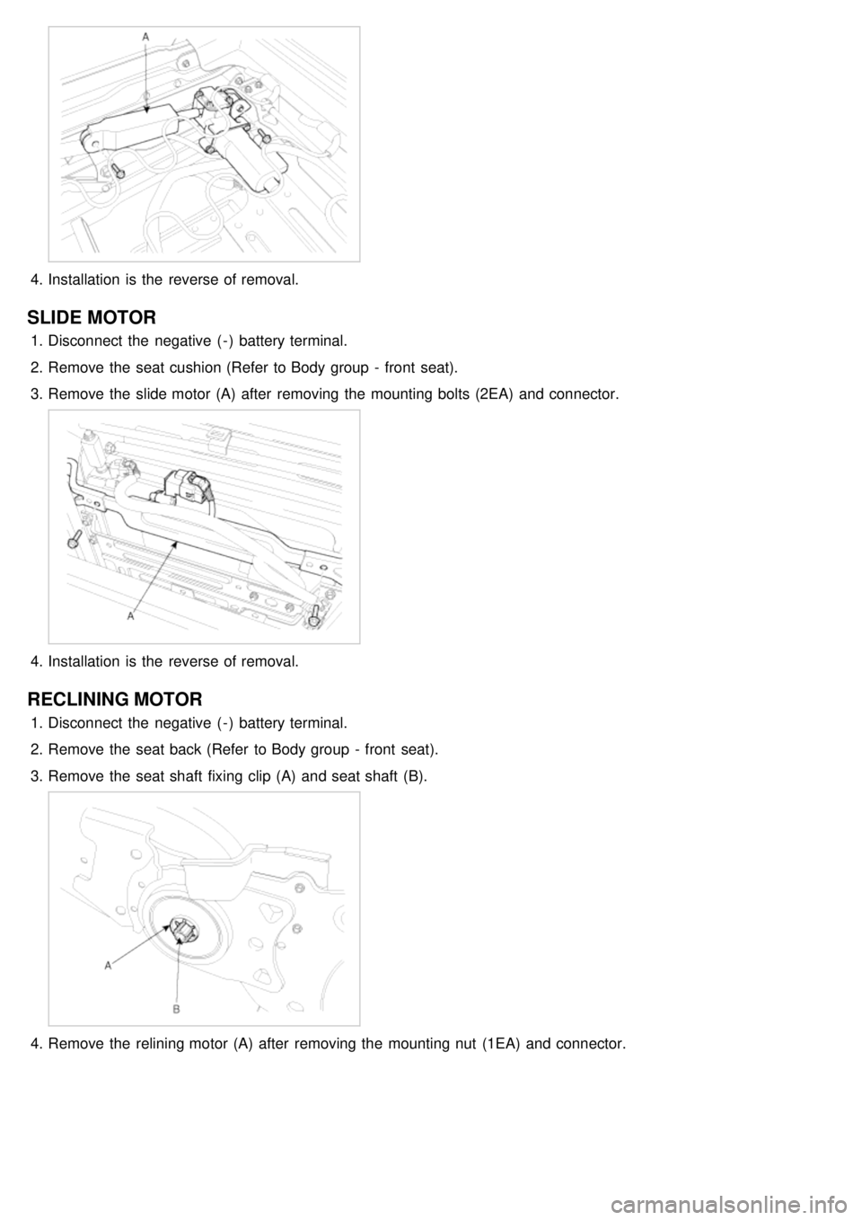
1.Disconnect the negative ( - ) battery terminal.
2. Remove the seat cushion (Refer to Body group - front seat).
3. Remove the slide motor (A) after removing the mounting bolts (2EA) and connector.
4.Installation is the reverse of removal.
RECLINING MOTOR
1.Disconnect the negative ( - ) battery terminal.
2. Remove the seat back (Refer to Body group - front seat).
3. Remove the seat shaft fixing clip (A) and seat shaft (B).
4.Remove the relining motor (A) after removing the mounting nut (1EA) and connector.
Page 1270 of 1575

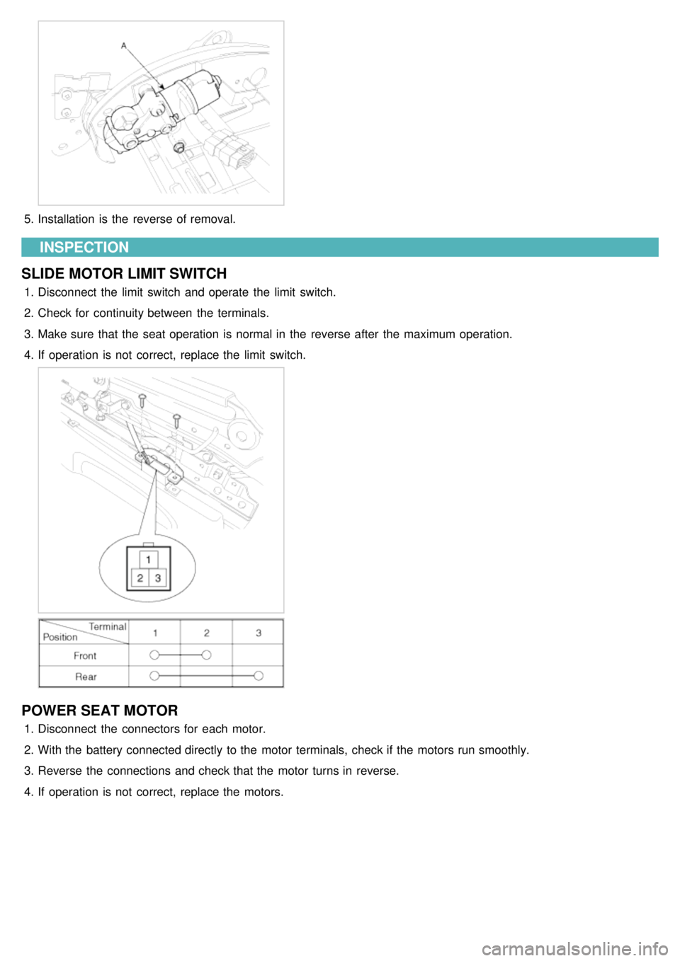
5.Installation is the reverse of removal.
INSPECTION
SLIDE MOTOR LIMIT SWITCH
1. Disconnect the limit switch and operate the limit switch.
2. Check for continuity between the terminals.
3. Make sure that the seat operation is normal in the reverse after the maximum operation.
4. If operation is not correct, replace the limit switch.
POWER SEAT MOTOR
1.Disconnect the connectors for each motor.
2. With the battery connected directly to the motor terminals, check if the motors run smoothly.
3. Reverse the connections and check that the motor turns in reverse.
4. If operation is not correct, replace the motors.