check engine KIA CARNIVAL 2007 Repair Manual
[x] Cancel search | Manufacturer: KIA, Model Year: 2007, Model line: CARNIVAL, Model: KIA CARNIVAL 2007Pages: 1575, PDF Size: 44.86 MB
Page 492 of 1575
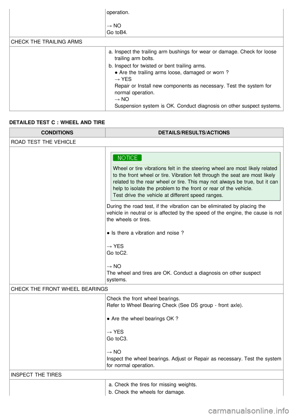
operation.
→ NO
Go toB4.
CHECK THE TRAILING ARMS
a.Inspect the trailing arm bushings for wear or damage. Check for loose
trailing arm bolts.
b. Inspect for twisted or bent trailing arms.
● Are the trailing arms loose, damaged or worn ?
→ YES
Repair or Install new components as necessary. Test the system for
normal operation.
→ NO
Suspension system is OK. Conduct diagnosis on other suspect systems.
DETAILED TEST C : WHEEL AND TIRE CONDITIONS DETAILS/RESULTS/ACTIONS
ROAD TEST THE VEHICLE
Wheel or tire vibrations felt in the steering wheel are most likely related
to the front wheel or tire. Vibration felt through the seat are most likely
related to the rear wheel or tire. This may not always be true, but it can
help to isolate the problem to the front or rear of the vehicle.
Test drive the vehicle at different speed ranges.
During the road test, if the vibration can be eliminated by placing the
vehicle in neutral or is affected by the speed of the engine, the cause is not
the wheels or tires.
● Is there a vibration and noise ?
→ YES
Go to C2.
→ NO
The wheel and tires are OK. Conduct a diagnosis on other suspect
systems.
CHECK THE FRONT WHEEL BEARINGS Check the front wheel bearings.
Refer to Wheel Bearing Check (See DS group - front axle).
● Are the wheel bearings OK ?
→ YES
Go to C3.
→ NO
Inspect the wheel bearings. Adjust or Repair as necessary. Test the system
for normal operation.
INSPECT THE TIRES
a.Check the tires for missing weights.
b. Check the wheels for damage.
Page 582 of 1575

2007 > 2.7L V6 GASOLINE >
SERVICE ADJUSTMENT PROCEDURE
CHECKING STEERING WHEEL FREE PLAY
1. Start the engine and with the steering wheel in the straight ahead position.
2. Measure the play while turning the steering wheel to the left and right.
Standard value :
Steering wheel free play : 30 mm (1.1 in)
3.If the play exceeds the standard value, inspect the connection between the steering shaft and tie rod ends.
CHECKING STEERING ANGLE
1.Place the front wheel on a turning radius gauge and measure the steering angle.
Standard value
VRS on Inner
38.64 °
Outer 31.78 °
VRS off Inner
41.91 °
Outer 33.54 °
2. If the measured value is not within the standard value, adjust the toe and inspect again.
CHECKING THE TIE ROD END BALL JOINT STARTING TORQUE
1.Disconnect tie rod and knuckle with the special tool (09568- 4A000).
Page 584 of 1575

CHECKING POWER STEERING BELT TENSION
Refer to EM group(Timing system).
CHECKING POWER STEERING FLUID LEVEL
1.Position the vehicle on a level surface.
2. Start the engine. With the vehicle kept stationary, turn the steering wheel several times continuously to raise the
fluid temperature to 50- 60°C (122 - 140°F).
3. With the engine at idle, turn the steering wheel fully clockwise and counter- clockwise several times.
4. Make sure that there is no foaming or cloudiness in the reservoir fluid.
5. Stop the engine and check for any difference in fluid level between a stationary and a running engine.
a.If the fluid level varies 5 mm (0.2 in) or more, bleed the system again.
b. If the fluid level suddenly rises after stopping the engine, further bleeding is required.
c. Incomplete bleeding will produce a chattering sound in the pump and noise in the flow control valve, and
lead to decreased durability of the pump.
REPLACING POWER STEERING FLUID
1.Jack up the front wheels and support them with jackstands.
2. Disconnect the return hose from the oil reservoir and plug the oil reservoir.
3. Connect a vinyl hose to the disconnected return hose, and drain the oil into a container.
4. Remove the fuel pump fuse, then start the engine and wait for the engine to stall. Next, while operating the starting
motor intermittently, turn the steering wheel all the way to the left and then to the right several times to drain the
fluid.
5. Connect the return hoses, then fill the oil reservoir with the specified fluid.
6. Reinstall the fuel pump fuse.
7. Start the engine. Check for oil leakage.
8. Stop the engine.
9. Bleed the system.
Power steering fluid type : PSF - 3
Total quantity : Approx 1.1 liter
AIR BLEEDING
1.Remove the fuel pump fuse, then start the engine and wait for the engine to stall. Next, while operating the starting
motor intermittently (for 15 ~ 20 seconds), turn the steering wheel all the way to the left and then to the right five or
six times.
Page 646 of 1575
2007 > 2.7L V6 GASOLINE >
TROUBLESHOOTING
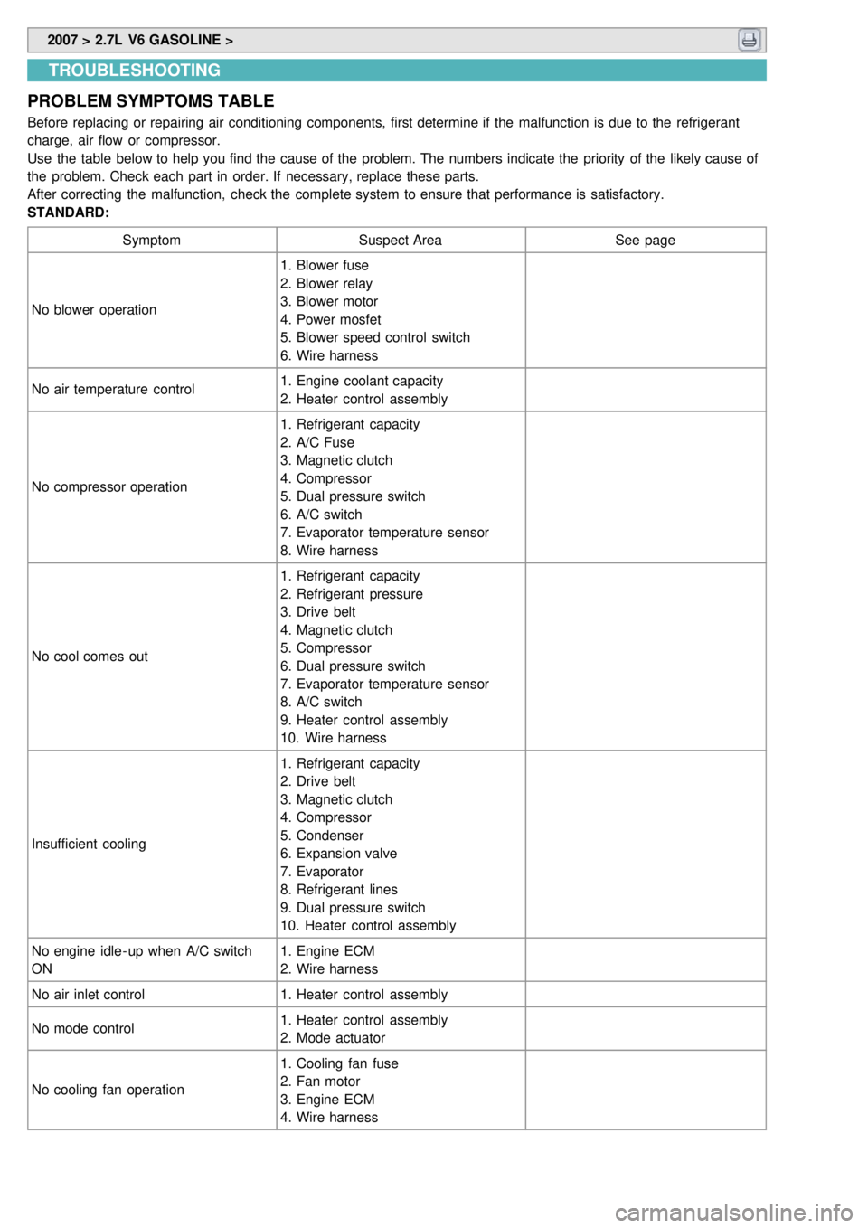
PROBLEM SYMPTOMS TABLE
Before replacing or repairing air conditioning components, first determine if the malfunction is due to the refrigerant
charge, air flow or compressor.
Use the table below to help you find the cause of the problem. The numbers indicate the priority of the likely cause of
the problem. Check each part in order. If necessary, replace these parts.
After correcting the malfunction, check the complete system to ensure that performance is satisfactory.
STANDARD:
Symptom Suspect Area See page
No blower operation 1. Blower fuse
2. Blower relay
3. Blower motor
4. Power mosfet
5. Blower speed control switch
6. Wire harness
No air temperature control 1. Engine coolant capacity
2. Heater control assembly
No compressor operation 1. Refrigerant capacity
2. A/C Fuse
3. Magnetic clutch
4. Compressor
5. Dual pressure switch
6. A/C switch
7. Evaporator temperature sensor
8. Wire harness
No cool comes out 1. Refrigerant capacity
2. Refrigerant pressure
3. Drive belt
4. Magnetic clutch
5. Compressor
6. Dual pressure switch
7. Evaporator temperature sensor
8. A/C switch
9. Heater control assembly
10. Wire harness
Insufficient cooling 1. Refrigerant capacity
2. Drive belt
3. Magnetic clutch
4. Compressor
5. Condenser
6. Expansion valve
7. Evaporator
8. Refrigerant lines
9. Dual pressure switch
10. Heater control assembly
No engine idle - up when A/C switch
ON 1. Engine ECM
2. Wire harness
No air inlet control 1. Heater control assembly
No mode control 1. Heater control assembly
2. Mode actuator
No cooling fan operation 1. Cooling fan fuse
2. Fan motor
3. Engine ECM
4. Wire harness
Page 665 of 1575
2007 > 2.7L V6 GASOLINE >
INSPECTION
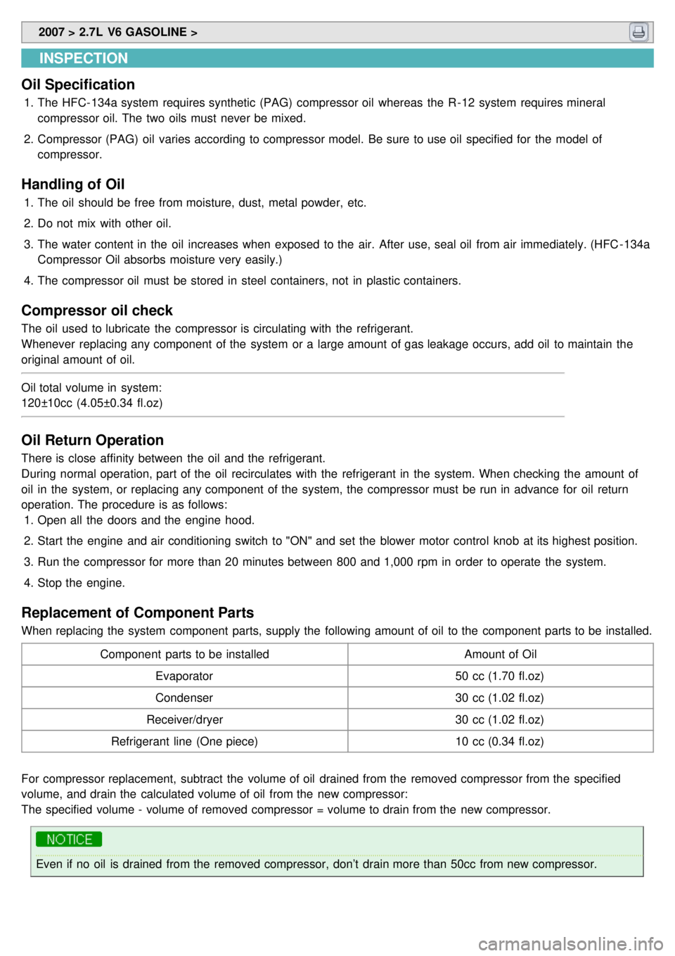
Oil Specification
1. The HFC- 134a system requires synthetic (PAG) compressor oil whereas the R- 12 system requires mineral
compressor oil. The two oils must never be mixed.
2. Compressor (PAG) oil varies according to compressor model. Be sure to use oil specified for the model of
compressor.
Handling of Oil
1.The oil should be free from moisture, dust, metal powder, etc.
2. Do not mix with other oil.
3. The water content in the oil increases when exposed to the air. After use, seal oil from air immediately. (HFC - 134a
Compressor Oil absorbs moisture very easily.)
4. The compressor oil must be stored in steel containers, not in plastic containers.
Compressor oil check
The oil used to lubricate the compressor is circulating with the refrigerant.
Whenever replacing any component of the system or a large amount of gas leakage occurs, add oil to maintain the
original amount of oil.
Oil total volume in system:
120±10cc (4.05±0.34 fl.oz)
Oil Return Operation
There is close affinity between the oil and the refrigerant.
During normal operation, part of the oil recirculates with the refrigerant in the system. When checking the amount of
oil in the system, or replacing any component of the system, the compressor must be run in advance for oil return
operation. The procedure is as follows:
1. Open all the doors and the engine hood.
2. Start the engine and air conditioning switch to "ON" and set the blower motor control knob at its highest position.
3. Run the compressor for more than 20 minutes between 800 and 1,000 rpm in order to operate the system.
4. Stop the engine.
Replacement of Component Parts
When replacing the system component parts, supply the following amount of oil to the component parts to be installed.
Component parts to be installed Amount of Oil
Evaporator 50 cc (1.70 fl.oz)
Condenser 30 cc (1.02 fl.oz)
Receiver/dryer 30 cc (1.02 fl.oz)
Refrigerant line (One piece) 10 cc (0.34 fl.oz)
For compressor replacement, subtract the volume of oil drained from the removed compressor from the specified
volume, and drain the calculated volume of oil from the new compressor:
The specified volume - volume of removed compressor = volume to drain from the new compressor.
Even if no oil is drained from the removed compressor, don’t drain more than 50cc from new compressor.
Page 869 of 1575
2007 > 2.7L V6 GASOLINE >
Operation and Leakage Check
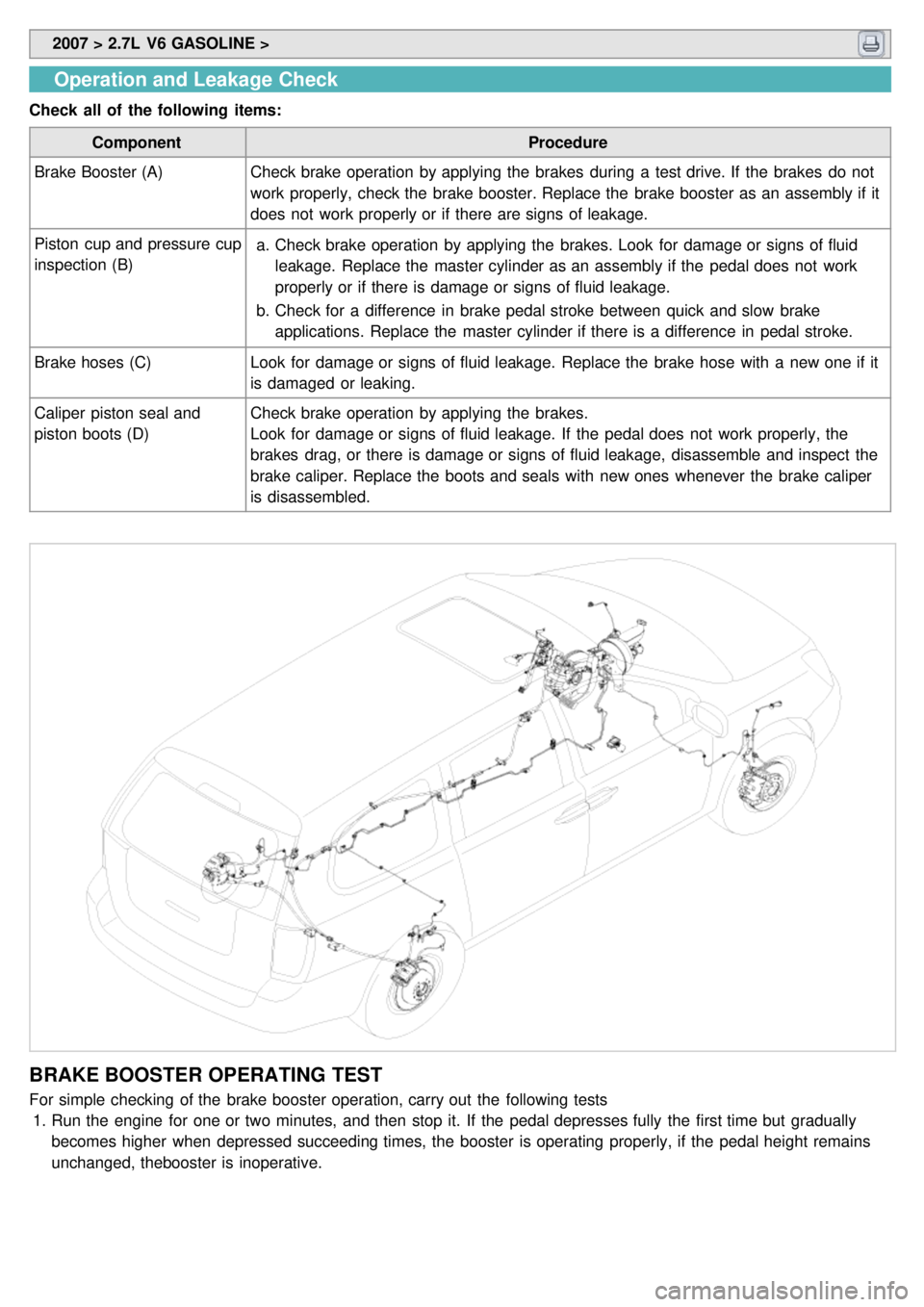
Check all of the following items:
Component Procedure
Brake Booster (A) Check brake operation by applying the brakes during a test drive. If the brakes do not
work properly, check the brake booster. Replace the brake booster as an assembly if it
does not work properly or if there are signs of leakage.
Piston cup and pressure cup
inspection (B) a.
Check brake operation by applying the brakes. Look for damage or signs of fluid
leakage. Replace the master cylinder as an assembly if the pedal does not work
properly or if there is damage or signs of fluid leakage.
b. Check for a difference in brake pedal stroke between quick and slow brake
applications. Replace the master cylinder if there is a difference in pedal stroke.
Brake hoses (C) Look for damage or signs of fluid leakage. Replace the brake hose with a new one if it
is damaged or leaking.
Caliper piston seal and
piston boots (D) Check brake operation by applying the brakes.
Look for damage or signs of fluid leakage. If the pedal does not work properly, the
brakes drag, or there is damage or signs of fluid leakage, disassemble and inspect the
brake caliper. Replace the boots and seals with new ones whenever the brake caliper
is disassembled.
BRAKE BOOSTER OPERATING TEST
For simple checking of the brake booster operation, carry out the following tests
1. Run the engine for one or two minutes, and then stop it. If the pedal depresses fully the first time but gradually
becomes higher when depressed succeeding times, the booster is operating properly, if the pedal height remains
unchanged, thebooster is inoperative.
Page 870 of 1575
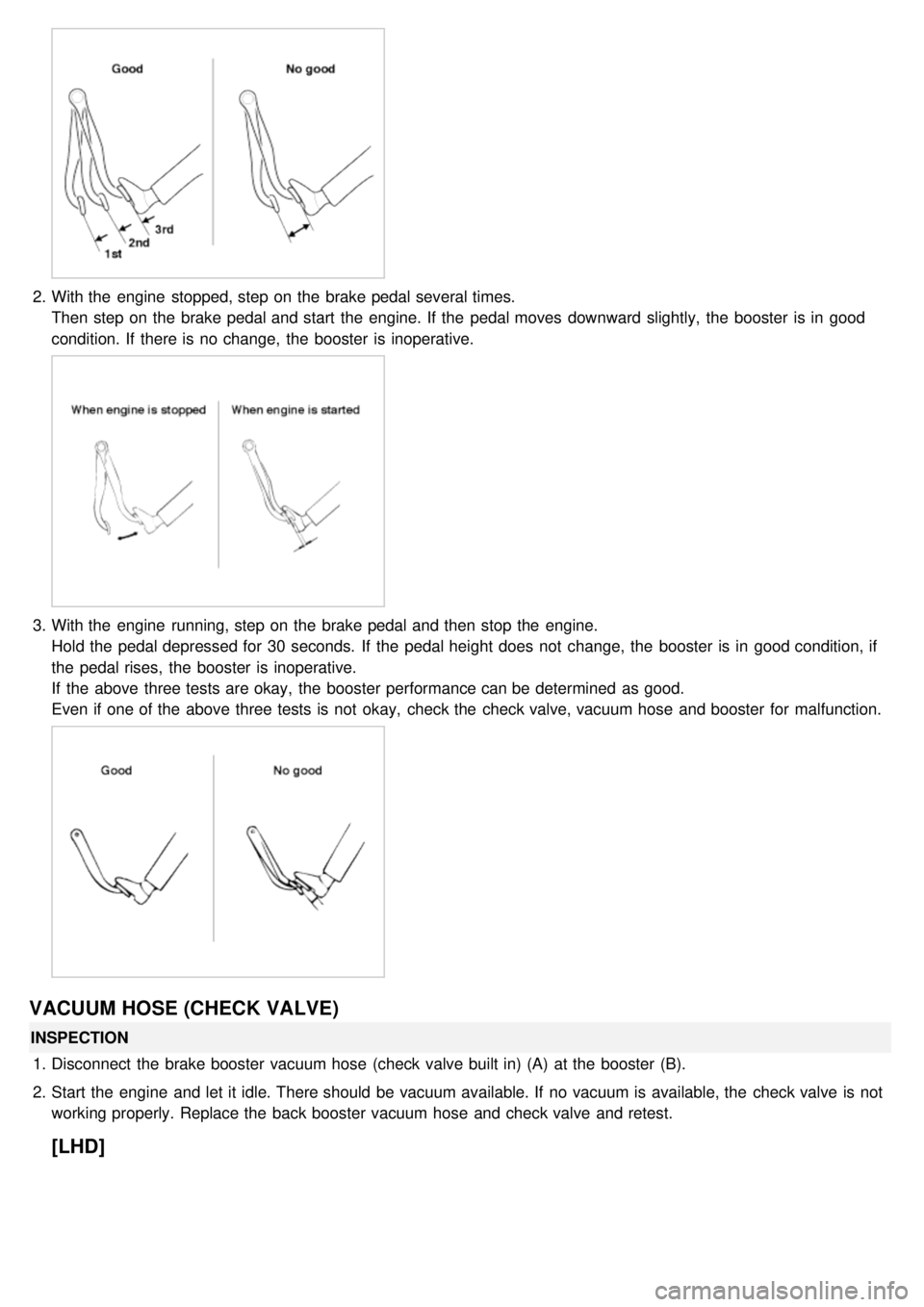
2.With the engine stopped, step on the brake pedal several times.
Then step on the brake pedal and start the engine. If the pedal moves downward slightly, the booster is in good
condition. If there is no change, the booster is inoperative.
3.With the engine running, step on the brake pedal and then stop the engine.
Hold the pedal depressed for 30 seconds. If the pedal height does not change, the booster is in good condition, if
the pedal rises, the booster is inoperative.
If the above three tests are okay, the booster performance can be determined as good.
Even if one of the above three tests is not okay, check the check valve, vacuum hose and booster for malfunction.
VACUUM HOSE (CHECK VALVE)
INSPECTION
1. Disconnect the brake booster vacuum hose (check valve built in) (A) at the booster (B).
2. Start the engine and let it idle. There should be vacuum available. If no vacuum is available, the check valve is not
working properly. Replace the back booster vacuum hose and check valve and retest.
[LHD]
Page 872 of 1575

BRAKE SWITCH CLEARANCE
Screw in the brake switch until its plunger is fully depressed (threded end (A) touching the pad (B) on the pedal arm)
then brake off the switch 3/4 turn to make 0.5 ~ 1.0 mm(0.0197 ~ 0.0394 in.) of clearance between the brake switch
connector. Make sure that the brake lights go off when the pedal is released.
PEDAL FREE PLAY
1.With the engine off, inspect the pedal free play (A) on the pedal pad (B) by pushing the pedal by hand.
Free play: 3 ~ 8 mm (0.12 ~ 0.31 in.)
2.If the pedal free play is out of specification, adjust the brake switch (C). If the pedal free play is insufficient, it may
result in brake drag.
INSPECTION OF FRONT DISC BRAKE PAD
1.Check the brake pad thickness through the caliper body inspection hole.
Pad thickness
Standard value : 10.5 mm ( 0.41 in)
Service limit : 2 mm (0.0787 in)
Page 928 of 1575

2007 > 2.7L V6 GASOLINE >
DESCRIPTION
This specification applies to HCU(Hydraulic Control Unit) and ECU(Electronic Control Unit) of the HECU.(Hydraulic and
Electronic Control Unit)
This specification is for the wiring design and installation of ABS/TCS/ESC ECU.
This unit has the functions as follows.
a. Input of signal from Pressure sensor, Steering angle sensor, Yaw & Lateral G sensor, the wheel speed sensors
attached to each wheel.
b. Control of braking force / traction force/ yaw moment.
c. Failsafe function.
d. Self diagnosis function.
e. Interface with the external diagnosis tester.
Installation position : engine compartment a. Brake tube length from Master cylinder port to HECU inlet port should be max. 1m
b. The position should not be close to the engine block and not lower than the wheel.
OPERATION
The ECU shall be put into operation by switching on the operating voltage (IGN).
On completion of the initialization phase, the ECU shall be ready for operation.
In the operating condition, the ECU shall be ready, within the specified limits (voltage and temperature), to process the
signals offered by the various sensors and switches in accordance with the control algorithm defined by the software
and to control the hydraulic and electrical actuators.
Wheel Sensor signal processing
The ECU shall receive wheel speed signal from the four active wheel sensors.
The wheel signals are converted to voltage signal by the signal conditioning circuit after receiving current signal from
active wheel sensors and given as input to the MCU.
Solenoid Valve Control
When one side of the valve coil is connected to the positive voltage that is provided through the valve relay and the
other side is connected to the ground by the semiconductor circuit, the solenoid valve goes into operation.
The electrical function of the coils are always monitored by the valve test pulse under normal operation conditions.
Voltage limits
a.Overvoltage
When overvoltage is detected(above 16.8 V), the ECU switches off the valve relay and shuts down the system.
When voltage is returned to operating range, the system goes back to the normal condition after the initialization
phase.
b. Undervoltage
In the event of undervoltage(below 9.3 V), ABS control shall be inhibited and the warning lamp shall be turned on.
When voltage is returned to operating range, the warning lamp is switched off and ECU returns to normal operating
mode.
Pump Motor Checking
The ECU performs a pump motor test at a speed of 15km/h once after IGN is switched on.
Diagnostic Interface
Failures detected by the ECU are encoded on the ECU, stored in a EEPROM and read out by diagnostic equipment
when the ignition switch is turned on.
The diagnosis interface can also be used for testing the ECU during production of the ECU and for actuating the HCU
(Air - bleeding line or Roll and Brake Test line).
Warning Lamp module
Page 934 of 1575

2007 > 2.7L V6 GASOLINE >
STANDARD FLOW OF DIAGNOSTIC TROUBLESHOOTING
NOTES WITH REGARD TO DIAGNOSIS
The phenomena listed in the following table are not abnormal.
Phenomenon Explanation
System check sound When starting the engine, a thudding sound can sometimes be heard coming
from inside the engine compartment. This is because the system operation check
is being performed.
ABS operation sound a.Sound of the motor inside the ABS hydraulic unit operation (whine).
b. Sound is generated along with vibration of the brake pedal (scraping).
c. When ABS operates, sound is generated from the vehicle chassis due to
repeated brake application and release
(Thump : suspension; squeak: tires)
ABS operation (Long braking
distance) For road surfaces such as snow- covered and gravel roads, the braking distance
for vehicles with ABS can sometimes be longer than that for other vehicles.
Accordingly, advise the customer to drive safely on such roads by lowering the
vehicle speed.
Diagnosis detection conditions can vary depending on the diagnosis code. When checking the trouble symptom after
the diagnosis code has been erased, ensure that the requirements listed in "Comment" are met.
SCAN TOOL (PRO) CHECK
1. Turn the ignition switch OFF.
2. Connector the Scan tool to the 16P data link connector located the driver's side kick panel.