KIA CARNIVAL 2007 Workshop Manual
CARNIVAL 2007
KIA
KIA
https://www.carmanualsonline.info/img/2/57045/w960_57045-0.png
KIA CARNIVAL 2007 Workshop Manual
Page 71 of 1575
INSTALLATION
Installation is in the reverse order of removal.
Perform the following :a. Adjust the shift cable.
b. Refill the engine with engine oil.
c. Refill the transaxle with fluid.
d. Refill the radiator with engine coolant.
e. Bleed air from the cooling system with the heater valve open.
f. Clean the battery posts and cable terminals with sandpaper assemble them, then apply grease to prevent
corrosion.
g. Inspect for fuel leakage.
After assembling the fuel line, turn on the ignition switch (do not operate the starter) so that the fuel pump runs for
approximately two seconds and fuel line pressurizes.
Repeat this operation two or three times, then check for fuel leakage at any point in the fuel line.
Page 154 of 1575
2007 > 2.7L V6 GASOLINE >
REMOVAL
IGNITION COIL
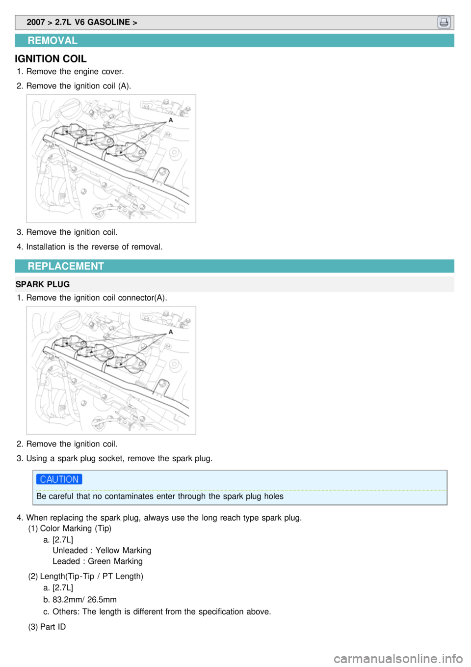
1. Remove the engine cover.
2. Remove the ignition coil (A).
3.Remove the ignition coil.
4. Installation is the reverse of removal.
REPLACEMENT
SPARK PLUG
1. Remove the ignition coil connector(A).
2.Remove the ignition coil.
3. Using a spark plug socket, remove the spark plug.
Be careful that no contaminates enter through the spark plug holes
4. When replacing the spark plug, always use the long reach type spark plug.
(1) Color Marking (Tip)
a. [2.7L]
Unleaded : Yellow Marking
Leaded : Green Marking
(2) Length(Tip - Tip / PT Length)
a. [2.7L]
b. 83.2mm/ 26.5mm
c. Others: The length is different from the specification above.
(3) Part ID
Page 166 of 1575
2007 > 2.7L V6 GASOLINE >
REMOVAL
1.Disconnect the battery negative terminal first, then the positive terminal.
2. Disconnect the alternator connector, and remove the cable from alternator "B" terminal.
3. Remove the drive belt.
4. Pull out the through bolt and then remove the alternator(A).
5.Installation is the reverse of removal.
DISASSEMBLY
1.Remove the alternator cover(A) using a screw driver(B).
2.Remove the slip ring guide(A).
3. Loosen the mounting bolts(B) and disconnect the brush holder assembly(C).
4.Remove the rectifler(A) with 4 screws.
Page 167 of 1575
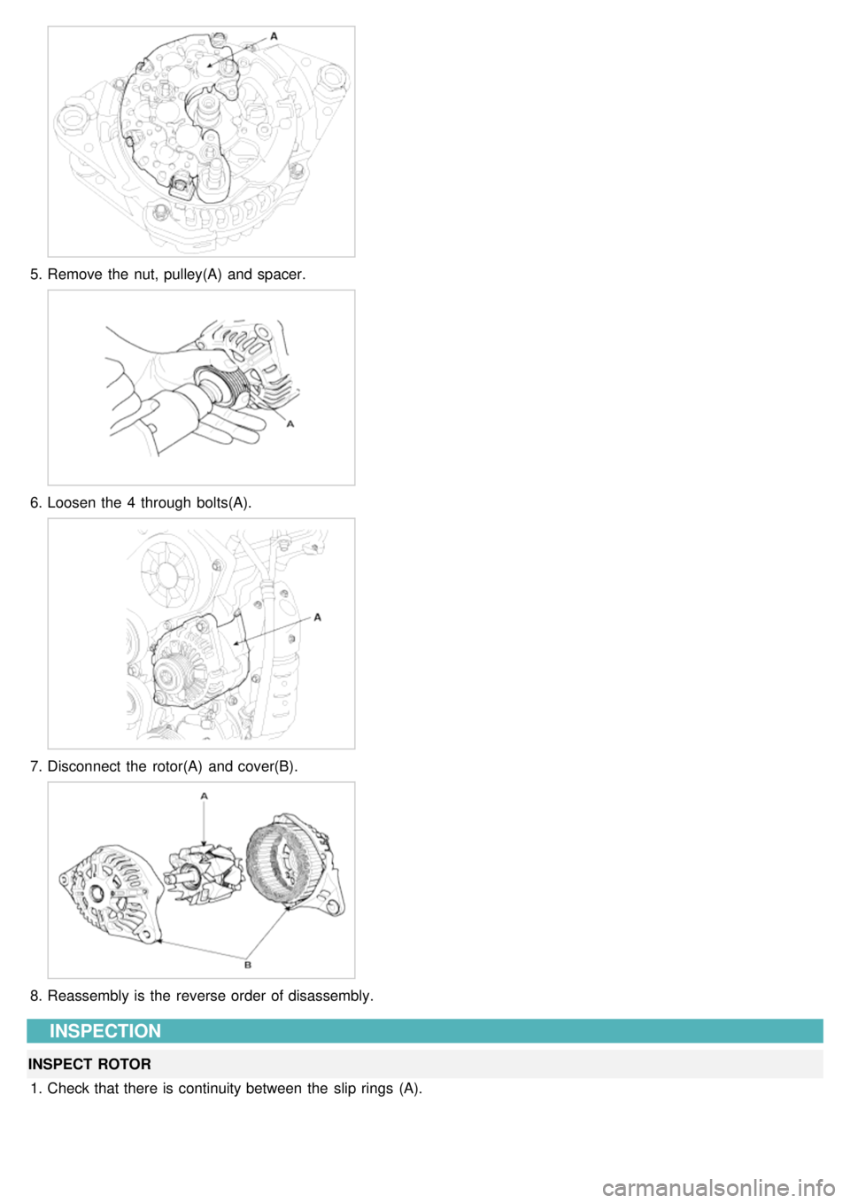
5.Remove the nut, pulley(A) and spacer.
6.Loosen the 4 through bolts(A).
7.Disconnect the rotor(A) and cover(B).
8.Reassembly is the reverse order of disassembly.
INSPECTION
INSPECT ROTOR
1. Check that there is continuity between the slip rings (A).
Page 180 of 1575
2007 > 2.7L V6 GASOLINE >
REMOVAL
STATATER
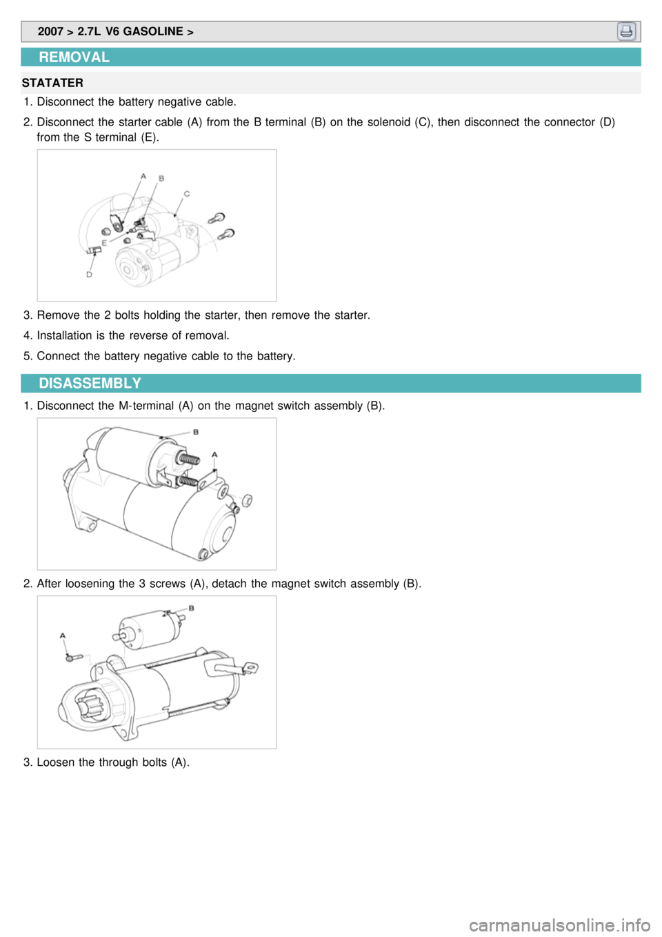
1. Disconnect the battery negative cable.
2. Disconnect the starter cable (A) from the B terminal (B) on the solenoid (C), then disconnect the connector (D)
from the S terminal (E).
3.Remove the 2 bolts holding the starter, then remove the starter.
4. Installation is the reverse of removal.
5. Connect the battery negative cable to the battery.
DISASSEMBLY
1.Disconnect the M- terminal (A) on the magnet switch assembly (B).
2.After loosening the 3 screws (A), detach the magnet switch assembly (B).
3.Loosen the through bolts (A).
Page 182 of 1575
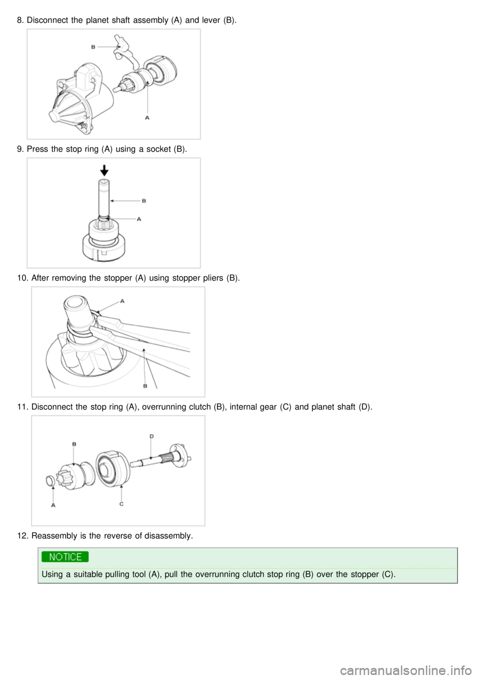
8.Disconnect the planet shaft assembly (A) and lever (B).
9.Press the stop ring (A) using a socket (B).
10. After removing the stopper (A) using stopper pliers (B).
11.Disconnect the stop ring (A), overrunning clutch (B), internal gear (C) and planet shaft (D).
12.Reassembly is the reverse of disassembly.
Using a suitable pulling tool (A), pull the overrunning clutch stop ring (B) over the stopper (C).
Page 186 of 1575
INSPECT OVERRUNNING CLUTCH
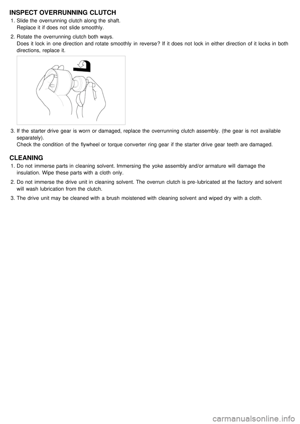
1.Slide the overrunning clutch along the shaft.
Replace it if does not slide smoothly.
2. Rotate the overrunning clutch both ways.
Does it lock in one direction and rotate smoothly in reverse? If it does not lock in either direction of it locks in both
directions, replace it.
3.If the starter drive gear is worn or damaged, replace the overrunning clutch assembly. (the gear is not available
separately).
Check the condition of the flywheel or torque converter ring gear if the starter drive gear teeth are damaged.
CLEANING
1.Do not immerse parts in cleaning solvent. Immersing the yoke assembly and/or armature will damage the
insulation. Wipe these parts with a cloth only.
2. Do not immerse the drive unit in cleaning solvent. The overrun clutch is pre- lubricated at the factory and solvent
will wash lubrication from the clutch.
3. The drive unit may be cleaned with a brush moistened with cleaning solvent and wiped dry with a cloth.
Page 208 of 1575
INSTALLATION
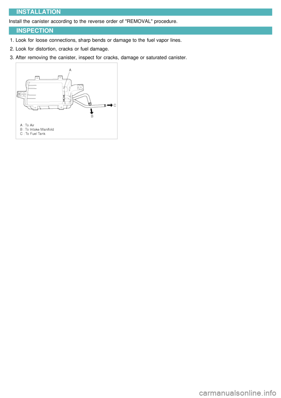
Install the canister according to the reverse order of "REMOVAL" procedure.
INSPECTION
1.Look for loose connections, sharp bends or damage to the fuel vapor lines.
2. Look for distortion, cracks or fuel damage.
3. After removing the canister, inspect for cracks, damage or saturated canister.
Page 321 of 1575
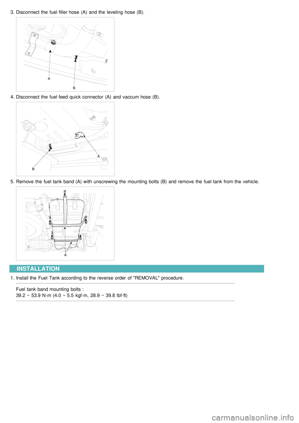
3.Disconnect the fuel filler hose (A) and the leveling hose (B).
4.Disconnect the fuel feed quick connector (A) and vaccum hose (B).
5.Remove the fuel tank band (A) with unscrewing the mounting bolts (B) and remove the fuel tank from the vehicle.
INSTALLATION
1.Install the Fuel Tank according to the reverse order of "REMOVAL" procedure.
Fuel tank band mounting bolts :
39.2 ~ 53.9 N·m (4.0 ~ 5.5 kgf·m, 28.9 ~ 39.8 lbf·ft)
Page 324 of 1575
INSTALLATION
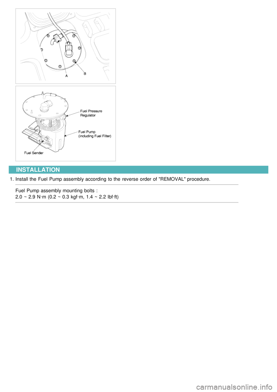
1.Install the Fuel Pump assembly according to the reverse order of "REMOVAL" procedure.
Fuel Pump assembly mounting bolts :
2.0 ~ 2.9 N·m (0.2 ~ 0.3 kgf·m, 1.4 ~ 2.2 lbf·ft)