display Lancia Musa 2009 Owner handbook (in English)
[x] Cancel search | Manufacturer: LANCIA, Model Year: 2009, Model line: Musa, Model: Lancia Musa 2009Pages: 218, PDF Size: 3.7 MB
Page 68 of 218
67
SAFETY
DEVICES
STARTING
AND
DRIVING
WARNING
LIGHTS AND
MESSAGES
IN AN
EMERGENCY
MAINTENANCE
AND CARE
TECHNICALSPECIFICATIONS
INDEX
DASHBOARD
AND CONTROLS
CRUISE CONTROL
(constant speed
regulator)
(where provided)
It is a device able to support the dri-
ver, with electronic control, which al-
lows driving at speed over 30 km/h
on long and straight dry roads (e.g.:
motorways), at a desired speed, with-
out pressing the accelerator pedal.
Therefore it is not suggested to use
this device on extra-urban roads with
traffic. Do not use it in town.TO MEMORISE SPEED
Proceed as follows:
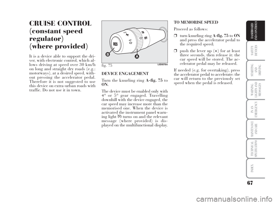
❒turn knurling ring A-fig. 75toON
and press the accelerator pedal to
the required speed;
❒push the lever up (+) for at least
three seconds, then release it: the
car speed will be stored. The ac-
celerator pedal may be released.
If needed (e.g. for overtaking), press
the accelerator pedal to accelerate: the
car will return to the previously set
speed when the pedal is released. DEVICE ENGAGEMENT
Turn the knurling ring A-fig. 75to
ON.
The device must be enabled only with
4
thor 5thgear engaged. Travelling
downhill with the device engaged, the
car speed may increase more than the
memorised one. When the device is
activated the instrument panel warn-
ing light Üturns on and the relevant
message (where provided) is dis-
played on the multifunctional display.
fig. 75L0D0076m
038-094 MUSA 1ed GB 11-07-2008 14:10 Pagina 67
Page 73 of 218
72
SAFETY
DEVICES
STARTING
AND
DRIVING
WARNING
LIGHTS AND
MESSAGES
IN AN
EMERGENCY
MAINTENANCE
AND CARE
TECHNICALSPECIFICATIONS
INDEX
DASHBOARD
AND CONTROLS
INERTIAL FUEL
CUT-OFF SWITCH
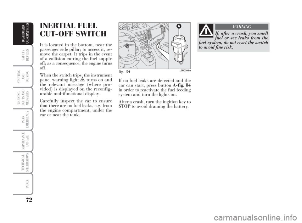
It is located in the bottom, near the
passenger side pillar; to access it, re-
move the carpet. It trips in the event
of a collision cutting the fuel supply
off; as a consequence, the engine turns
off.
When the switch trips, the instrument
panel warning light
èturns on and
the relevant message (where pro-
vided) is displayed on the reconfig-
urable multifunctional display.
Carefully inspect the car to ensure
that there are no fuel leaks, e.g. from
the engine compartment, under the
car or near the tank.
If, after a crash, you smell
fuel or see leaks from the
fuel system, do not reset the switch
to avoid fine risk.
WARNING
fig. 84L0D0388m
If no fuel leaks are detected and the
car can start, press button A-fig. 84
in order to reactivate the fuel feeding
system and turn the lights on.
After a crash, turn the ingition key to
STOPto avoid draining the battery.
038-094 MUSA 1ed GB 11-07-2008 14:10 Pagina 72
Page 81 of 218
80
SAFETY
DEVICES
STARTING
AND
DRIVING
WARNING
LIGHTS AND
MESSAGES
IN AN
EMERGENCY
MAINTENANCE
AND CARE
TECHNICALSPECIFICATIONS
INDEX
DASHBOARD
AND CONTROLS
TAILGATE CLOSING
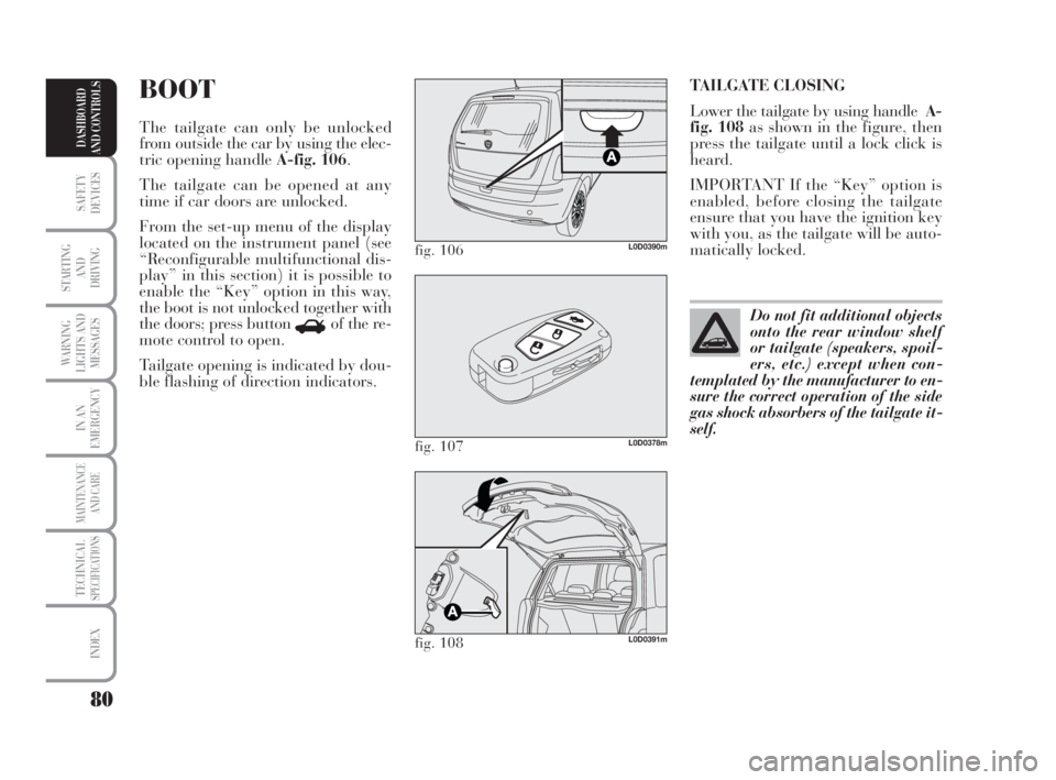
Lower the tailgate by using handleA-
fig. 108as shown in the figure, then
press the tailgate until a lock click is
heard.
IMPORTANT If the “Key” option is
enabled, before closing the tailgate
ensure that you have the ignition key
with you, as the tailgate will be auto-
matically locked.BOOT
The tailgate can only be unlocked
from outside the car by using the elec-
tric opening handle A-fig. 106.
The tailgate can be opened at any
time if car doors are unlocked.
From the set-up menu of the display
located on the instrument panel (see
“Reconfigurable multifunctional dis-
play” in this section) it is possible to
enable the “Key” option in this way,
the boot is not unlocked together with
the doors; press button
Rof the re-
mote control to open.
Tailgate opening is indicated by dou-
ble flashing of direction indicators.
fig. 106L0D0390m
fig. 107L0D0378m
fig. 108L0D0391m
Do not fit additional objects
onto the rear window shelf
or tailgate (speakers, spoil-
ers, etc.) except when con-
templated by the manufacturer to en-
sure the correct operation of the side
gas shock absorbers of the tailgate it-
self.
038-094 MUSA 1ed GB 11-07-2008 14:10 Pagina 80
Page 86 of 218
85
SAFETY
DEVICES
STARTING
AND
DRIVING
WARNING
LIGHTS AND
MESSAGES
IN AN
EMERGENCY
MAINTENANCE
AND CARE
TECHNICALSPECIFICATIONS
INDEX
DASHBOARD
AND CONTROLS
ABS SYSTEM
The car is fitted with an ABS braking
system, which prevents the wheels
from locking when braking, makes
the most of road grip and gives the
best control when emergency braking
under difficult road conditions.
The system is completed by EBD
(Electronic Braking Force Distribu-
tion), which distributes the braking
action between front and rear wheels.
IMPORTANT To achieve maximum
efficiency of the braking system, a
running in period of about 500 km is
required: during this time, avoid sud-
den, repeated and prolonged braking.SYSTEM INTERVENTION
Intervention of the ABS is detected by
a slight pulsing of the brake pedal ac-
companied by noise: such an event in-
dicates that you need to adjust your
speed to the type of road on which
you are travelling.
When the ABS intervenes it means
that you are approaching the grip
limit between tyres and road: slow
down to exploit all the available grip.
FAILURE INDICATIONS
ABS failure
It is indicated by the turning on of
warning light >on the instrument
panel together with the message
(where provided) shown on the re-
configurable multifunctional display
(see section “Warning lights and mes-
sages”).
In the case, the braking system will
work as normal without the extra po-
tentials offered by the ABS system.
Drive carefully to the nearest Lancia
Dealership to have the system
checked.When the ABS intervenes it
means that you are ap-
proaching the grip limit between
tyres and road: it is necessary to
slow down to adjust the speed ac-
cording to available grip.
WARNING
The ABS exploits the tyre
road grip to the full, but it
cannot improve it; you should there-
fore exercise great caution when dri-
ving on slippery surfaces without
taking unnecessary risks.
WARNING
038-094 MUSA 1ed GB 11-07-2008 14:10 Pagina 85
Page 87 of 218
86
SAFETY
DEVICES
STARTING
AND
DRIVING
WARNING
LIGHTS AND
MESSAGES
IN AN
EMERGENCY
MAINTENANCE
AND CARE
TECHNICALSPECIFICATIONS
INDEX
DASHBOARD
AND CONTROLS
EOBD SYSTEM
The EOBD system (European On
Board Diagnosis) allows continuous
diagnosis of the components of the car
correlated with emissions.
It also alerts the driver, by turning on
the warning light
Uon the instru-
ment panel (together with relevant
message on the multifunction display,
where provided) (see section “Warn-
ing lights and messages”), when these
components are no longer in peak
conditions.
The objective is:
❒to keep the system efficiency un-
der control;
❒to warn when a fault causes emis-
sion levels to increase;
❒to signal the need to replace worn
components. EBD failure
EBD failure is indicated by the turn-
ing on warning lights >andxon
the instrument panel, together with
the message (where provided) shown
on the multifunctional display (see
section “Warning lights and mes-
sages”).
In this case, the rear wheels may sud-
denly lock and the car may swerve.
Drive carefully to the nearest Lancia
Dealership to have the system
checked.
When the ABS intervenes,
a slight pulsing of the brake
pedal is felt. Do not lessen the pres-
sure of your foot on the pedal; main-
tain pressure on the brake without
hesitation; this will ensure that you
stop in the shortest possible space al-
lowed by the road conditions.
WARNING
If the warning lightxon
the instrument panel goes
on (and a message, were provided,
is shown in the multifunctional dis-
play), stop the car immediately and
contact your nearest Lancia Dealer-
ship. Leakage of hydraulic fluid
from the braking system will com-
promise functionality of the braking
system, either of the conventional
type or with ABS.
WARNING
038-094 MUSA 1ed GB 11-07-2008 14:10 Pagina 86
Page 88 of 218
87
SAFETY
DEVICES
STARTING
AND
DRIVING
WARNING
LIGHTS AND
MESSAGES
IN AN
EMERGENCY
MAINTENANCE
AND CARE
TECHNICALSPECIFICATIONS
INDEX
DASHBOARD
AND CONTROLS
The system also has a diagnostic con-
nector that can be interfaced with ap-
propriate tools, which makes it possi-
ble to read the error codes stored in
the control unit, together with a series
of specific parameters for engine op-
eration and diagnosis. This check can
also be carried out by the traffic po-
lice.
IMPORTANT After eliminating the
problem, to check the system com-
pletely, Lancia Dealerships are obliged
to run a bench test and, if necessary,
road tests which may also call for a
long journey.Sound system installation
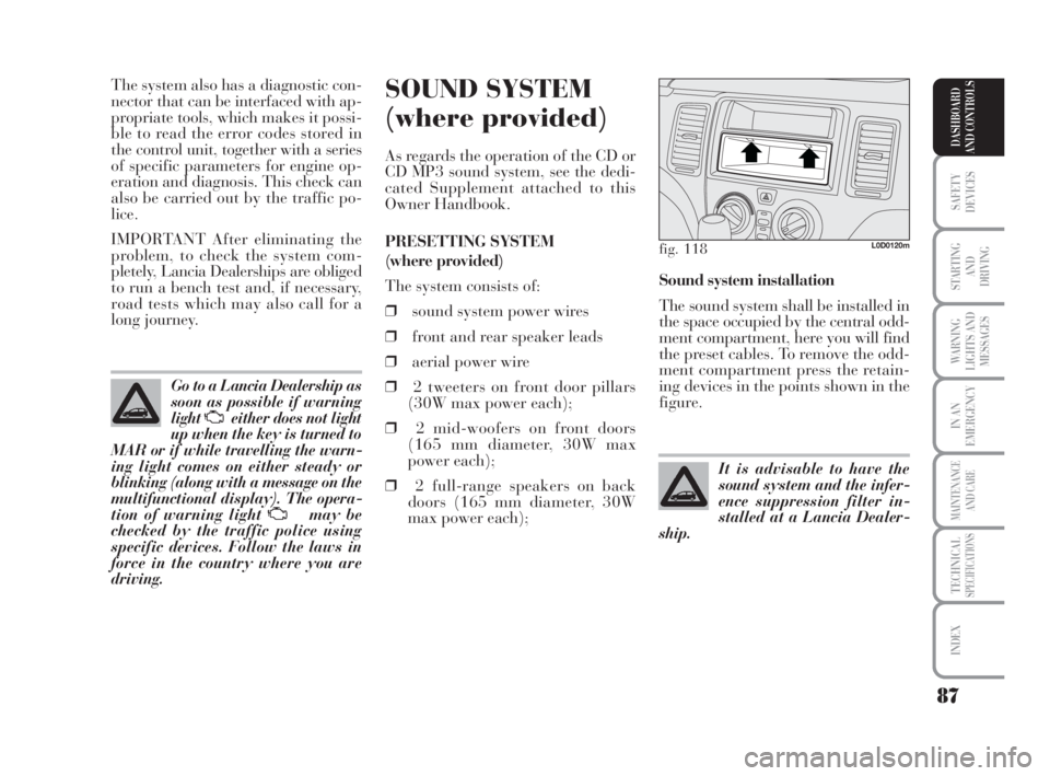
The sound system shall be installed in
the space occupied by the central odd-
ment compartment, here you will find
the preset cables. To remove the odd-
ment compartment press the retain-
ing devices in the points shown in the
figure.SOUND SYSTEM
(where provided)
As regards the operation of the CD or
CD MP3 sound system, see the dedi-
cated Supplement attached to this
Owner Handbook.
PRESETTING SYSTEM
(where provided)
The system consists of:
❒sound system power wires
❒front and rear speaker leads
❒aerial power wire
❒2 tweeters on front door pillars
(30W max power each);
❒2 mid-woofers on front doors
(165 mm diameter, 30W max
power each);
❒2 full-range speakers on back
doors (165 mm diameter, 30W
max power each); Go to a Lancia Dealership as
soon as possible if warning
lightUeither does not light
up when the key is turned to
MAR or if while travelling the warn-
ing light comes on either steady or
blinking (along with a message on the
multifunctional display). The opera-
tion of warning light Umay be
checked by the traffic police using
specific devices. Follow the laws in
force in the country where you are
driving.
fig. 118L0D0120m
It is advisable to have the
sound system and the infer-
ence suppression filter in-
stalled at a Lancia Dealer-
ship.
038-094 MUSA 1ed GB 11-07-2008 14:10 Pagina 87
Page 90 of 218
89
SAFETY
DEVICES
STARTING
AND
DRIVING
WARNING
LIGHTS AND
MESSAGES
IN AN
EMERGENCY
MAINTENANCE
AND CARE
TECHNICALSPECIFICATIONS
INDEX
DASHBOARD
AND CONTROLS
ELECTRICAL/ELECTRONIC
DEVICE INSTALLATION
The electric/electronic devices in-
stalled subsequent to the purchase of
the car and included in the after-sales
service must be marked:
Fiat Auto S.p.A. authorises the in-
stallation of transceiver devices on
condition that such installations are
carried out in a workmanlike fashion,
following the manufacturer’s instruc-
tions, at a specialised centre.
IMPORTANT Traffic police may not
allow the car on the road in the event
of assembly of devices which imply
modifications to the features of the
car. This may also cause lapse of war-
ranty in relation to faults caused by
the change or either directly or indi-
rectly related to it.
Fiat Auto S.p.A. shall not be liable for
damage caused by the installation of
accessories either not supplied or rec-
ommended by Fiat Auto S.p.A.
and/or installed in compliance with
the provided instructions.“DUALDRIVE”
ELECTRIC POWER
STEERING SYSTEM
The car is provided with the electri-
cally controlled power steering system
called “Dualdrive” working only with
ignition key at MARand engine run-
ning, that can be customised by the
driver according to the driving condi-
tions.
ACTIVATION/DEACTIVATION
(CITY function)
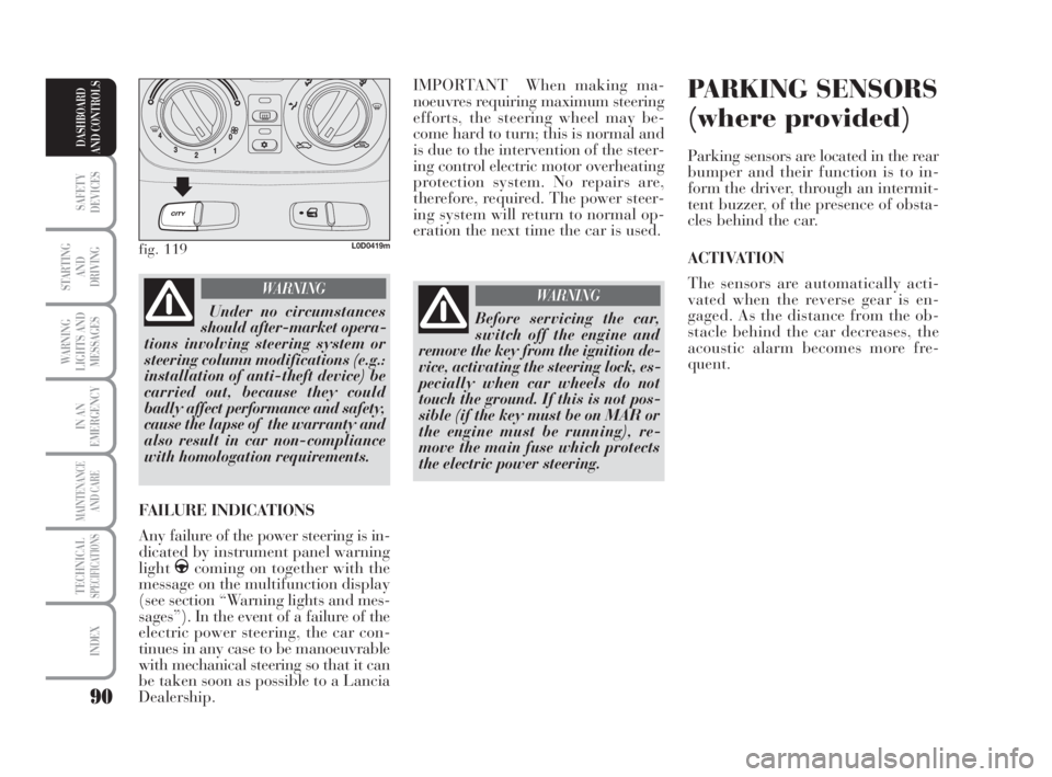
To enable/disable the function, press
the button fig. 119located on the cen-
tral area of the instrument dashboard.
The enabling of the function is sig-
nalled by the displaying of the word
CITY on the multifunctional display.
With CITY function on, wheel effort
is lighter, easing parking manoeuvres:
The function is particularly helpful
while driving in city centres. TRANSCEIVERS AND MOBILE
PHONES
Radio transceiver equipment (e.g.: e-
tacs mobile phones, HAM radio sys-
tems and the like) shall not be used
inside the car unless a separate aerial
is mounted on the roof.
The use of similar devices inside the
passenger compartment (without sep-
arate aerial) produces radio-frequency
electromagnetic fields which, ampli-
fied by the resonance effects inside the
passenger compartment, may cause
electrical systems equipping the car to
malfunction. This could compromise
safety in addition to constituting a po-
tential hazard for the passengers.
In addition, transmission and recep-
tion of these devices may be affected
by the shielding effect of the car body.
As concerns EC-approved mobile
phones (GSM, GPRS, UMTS), strictly
comply with the instructions for use
provided by the mobile phone’s man-
ufacturer.
038-094 MUSA 1ed GB 11-07-2008 14:10 Pagina 89
Page 91 of 218
90
SAFETY
DEVICES
STARTING
AND
DRIVING
WARNING
LIGHTS AND
MESSAGES
IN AN
EMERGENCY
MAINTENANCE
AND CARE
TECHNICALSPECIFICATIONS
INDEX
DASHBOARD
AND CONTROLS
IMPORTANT When making ma-
noeuvres requiring maximum steering
efforts, the steering wheel may be-
come hard to turn; this is normal and
is due to the intervention of the steer-
ing control electric motor overheating
protection system. No repairs are,
therefore, required. The power steer-
ing system will return to normal op-
eration the next time the car is used.PARKING SENSORS
(where provided)
Parking sensors are located in the rear
bumper and their function is to in-
form the driver, through an intermit-
tent buzzer, of the presence of obsta-
cles behind the car.
ACTIVATION
The sensors are automatically acti-
vated when the reverse gear is en-
gaged. As the distance from the ob-
stacle behind the car decreases, the
acoustic alarm becomes more fre-
quent.
fig. 119L0D0419m
Under no circumstances
should after-market opera-
tions involving steering system or
steering column modifications (e.g.:
installation of anti-theft device) be
carried out, because they could
badly affect performance and safety,
cause the lapse of the warranty and
also result in car non-compliance
with homologation requirements.
WARNING
FAILURE INDICATIONS
Any failure of the power steering is in-
dicated by instrument panel warning
light
gcoming on together with the
message on the multifunction display
(see section “Warning lights and mes-
sages”). In the event of a failure of the
electric power steering, the car con-
tinues in any case to be manoeuvrable
with mechanical steering so that it can
be taken soon as possible to a Lancia
Dealership.
Before servicing the car,
switch off the engine and
remove the key from the ignition de-
vice, activating the steering lock, es-
pecially when car wheels do not
touch the ground. If this is not pos-
sible (if the key must be on MAR or
the engine must be running), re-
move the main fuse which protects
the electric power steering.
WARNING
038-094 MUSA 1ed GB 11-07-2008 14:11 Pagina 90
Page 95 of 218
94
SAFETY
DEVICES
STARTING
AND
DRIVING
WARNING
LIGHTS AND
MESSAGES
IN AN
EMERGENCY
MAINTENANCE
AND CARE
TECHNICALSPECIFICATIONS
INDEX
DASHBOARD
AND CONTROLS
peratures, etc.) and it will then calcu-
late the amount of particulates trapped
by the filter. Since this filter physically
traps particulates, it shall be cleaned
(reclaimed) at regular intervals by
burning carbon particles. The regener-
ation procedure is controlled automat-
ically by the engine control unit ac-
cording to the filter conditions and the
conditions of use of the car. During the
regeneration procedure, the following
situations may occur: limited increase
of idle speed, activation of electric fan,
limited increase of smoke, high tem-
peratures at the exhaust. These are not
anomalies; they do not impair car be-
haviour and the environment. If the
dedicated message is displayed, refer to
section “Warning lights and messages”.PROTECTING THE
ENVIRONMENT
The devices for curtailing petrol engine
emissions are the following:
❒three-way catalytic converter;
❒Lambda sensors;
❒fuel evaporation prevention system.
In addition, do not let the engine run,
even for a test, with one or more spark
plugs disconnected.
The devices for curtailing diesel fuel en-
gine emissions are the following:
❒oxidising catalytic converter;
❒exhaust gas recirculation system
(E.G.R.);
❒diesel particulate filter (DPF)
DIESEL PARTICULATE
FILTER (DPF)
(for 1.3 Multijet 90 CV versions)
The Diesel Particulate Filter is a me-
chanical filter, integral with the exhaust
system, that physically traps particu-
lates present in the exhaust gases of
Diesel engines. The diesel particulate
filter has been adopted to eliminate al-
most totally particulates in compliance
with current / future law regulations.
During normal use of the car, the en-
gine control unit records a set of data
(e.g.: travel time, type of route, tem- During refuelling, attach the cap to
the device on the inside of the flap, as
shown in the figure.
IMPORTANT The sealing of the tank
may cause light pressuring in the
tank. A little breathing off, while
slackening the cap, is absolutely nor-
mal.
After refuelling, tighten the cap by
turning it clockwise until you hear one
or more clicks. Then turn the key
clockwise and remove it and close the
flap.
Do not place naked flames
or lit cigarettes near to the
fuel filler: fire risk. Keep your face
away from the fuel filler to prevent
breathing in harmful vapours.
WARNING
The catalytic converter de-
velops high temperature
during operation. Do not park on
grass, dry leaves, pine needles or
other flammable material: fire risk.
WARNING
038-094 MUSA 1ed GB 11-07-2008 14:11 Pagina 94
Page 111 of 218

110
STARTING
AND
DRIVING
WARNING
LIGHTS AND
MESSAGES
IN AN
EMERGENCY
MAINTENANCE
AND CARE
TECHNICALSPECIFICATIONS
INDEX
DASHBOARD
AND CONTROLS
SAFETY
DEVICES
MANUAL DEACTIVATION OF
FRONT AIRBAG AND SIDE BAG
ON PASSENGER’S SIDE
(where provided)
Whenever a child needs to be carried
on the front seat, the passenger’s front
airbag and the Side Bag (where pro-
vided) must be deactivated.
The warning light “on the instru-
ment panel stays on steadily until the
passenger’s front airbag and the Side
Bag (where provided) are re-acti-
vated.SIDE BAGS
(window bag)
(where provided)
SIDE BAG (where provided) fig.
19
It consists of an instant-inflating bag
housed in the front seat backrest. It
protects the chest of the passengers in
the event of a side crash of medium-
high severity.
To manually deactivate the
passenger’s front airbag and
the Side Bag (where provided), re-
fer to paragraph “Multifunctional
reconfigurable display” in section
“Dashboard and controls”.
WARNING
Do not cover the front seat
backrest with upholstery or
seat covers that hinder deployment
of the side bag.
WARNING
fig. 19L0C0147m
fig. 20L0C0148m
WINDOW BAG
(where provided) fig. 20
It consists of two “drop-down” bags
housed behind the side upholstery of
the roof and covered with finishing el-
ements that protect the head of front
and rear passengers in the event of a
side crash thanks to a wide bag de-
ployment area. Lineaccessori Lancia includes seat
covers enabling side bag deployment.
095-112 MUSA 1ed GB 10-07-2008 9:37 Pagina 110