clock Lancia Musa 2010 Owner handbook (in English)
[x] Cancel search | Manufacturer: LANCIA, Model Year: 2010, Model line: Musa, Model: Lancia Musa 2010Pages: 218, PDF Size: 3.71 MB
Page 19 of 218
18
SAFETY
STARTING
AND DRIVING
WARNING
LIGHTS AND
MESSAGES
IN AN
EMERGENCY
MAINTENANCE
AND CARE
TECHNICAL
SPECIFICA-
TIONS
INDEX
DASHBOARD
AND
CONTROLS
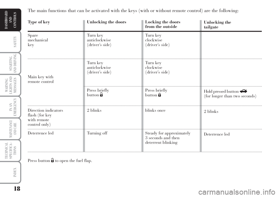
Type of key
Spare
mechanical
key
Main key with remote control
Direction indicators
flash (for key
with remote
control only)
Deterrence led
Press button Ëto open the fuel flap.
The main functions that can be activated with the keys (with or without remote control) are the following:
Locking the doors
from the outside
Turn key
clockwise
(driver’s side)
Turn key
clockwise
(driver’s side)
Press briefly
buttonÁ
blinks once
Steady for approximately
3 seconds and then
deterrent blinking Unlocking the
tailgate
Hold pressed button R
(for longer than two seconds)
2 blinks
Deterrence led Unlocking the doors
Turn key
anticlockwise
(driver’s side)
Turn key
anticlockwise
(driver’s side)
Press briefly
buttonË
2 blinks
Turning off
Page 20 of 218
19
SAFETY
STARTING
AND DRIVING
WARNING
LIGHTS AND
MESSAGES
IN AN
EMERGENCY
MAINTENANCE
AND CARE
TECHNICAL
SPECIFICA-
TIONS
INDEX
DASHBOARD
AND
CONTROLS
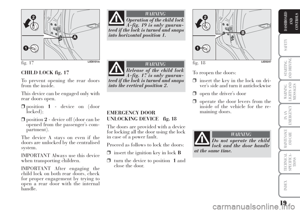
CHILD LOCK fig. 17
To prevent opening the rear doors
from the inside.
This device can be engaged only with
rear doors open.
❒position1- device on (door
locked);
❒position2- device off (door can be
opened from the passenger’s com-
partment).
The device A stays on even if the
doors are unlocked by the centralised
system.
IMPORTANT Always use this device
when transporting children.
IMPORTANT After engaging the
child lock on both rear doors, check
for proper engagement by trying to
open a rear door with the internal
handle.To reopen the doors:
❒insert the key in the lock on dri-
ver’s side and turn it anticlockwise
❒open the driver’s door
❒operate the door levers from the
inside of the vehicle for the re-
maining doors.
fig. 17L0D0101m
Operation of the child lock
A-fig. 19 is only guaran-
teed if the lock is turned and snaps
into horizontal position 1.
WARNING
Release of the child lock
A-fig. 17 is only guaran-
teed if the lock is turned and snaps
into the vertical position 2.
WARNING
EMERGENCY DOOR
UNLOCKING DEVICE fig. 18
The doors are provided with a device
for locking all the door using the lock
in case of a power fault.
Proceed as follows to lock the doors:
❒insert the ignition key in lock B
❒turn the device to position 1and
close the door.
fig. 18L0D0247
Do not operate the child
lock and the door handle
at the same time.
WARNING
Page 23 of 218
22
SAFETY
STARTING
AND DRIVING
WARNING
LIGHTS AND
MESSAGES
IN AN
EMERGENCY
MAINTENANCE
AND CARE
TECHNICAL
SPECIFICA-
TIONS
INDEX
DASHBOARD
AND
CONTROLS
MULTIFUNCTIONAL
DISPLAY
(on two-line modal
panel)
The car can be equipped with the mul-
tifunction display for showing useful in-
formation necessary when driving ac-
cording to settings. ENGINE
COOLANT TEMPERATURE
GAUGE fig. 23
Warning light Aindicates overheating
of the engine coolant. In this case, stop
the engine and contact a Lancia Deal-
ership. This shows the temperature of
the engine coolant fluid and starts
working when the fluid temperature ex-
ceeds approx. 50°C. In normal condi-
tions, the needle may point to different
positions according to use and the en-
gine cooling system management.
IMPORTANT The needle will point to
the lowest value of the scale (low tem-
perature) and warning light Awill
light up to indicate a fault in the sys-
tem. Go to a Lancia Dealership to
have the system checked.
If the needle reaches the red
area, stop the engine imme-
diately and contact a Lan-
cia Dealership.
fig. 24L0D0497m
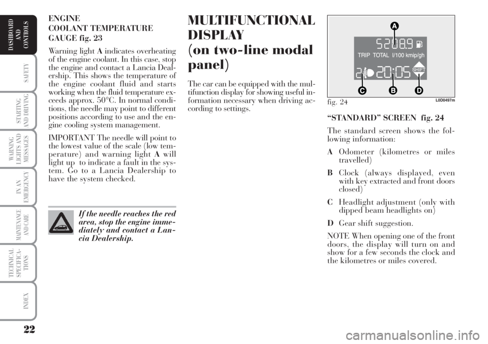
“STANDARD” SCREEN fig. 24
The standard screen shows the fol-
lowing information:
AOdometer (kilometres or miles
travelled)
BClock (always displayed, even
with key extracted and front doors
closed)
CHeadlight adjustment (only with
dipped beam headlights on)
DGear shift suggestion.
NOTE When opening one of the front
doors, the display will turn on and
show for a few seconds the clock and
the kilometres or miles covered.
Page 24 of 218
23
SAFETY
STARTING
AND DRIVING
WARNING
LIGHTS AND
MESSAGES
IN AN
EMERGENCY
MAINTENANCE
AND CARE
TECHNICAL
SPECIFICA-
TIONS
INDEX
DASHBOARD
AND
CONTROLS
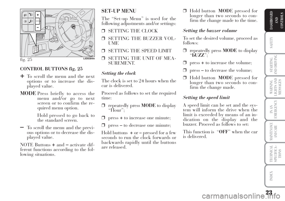
CONTROL BUTTONS fig. 25
+To scroll the menu and the next
options or to increase the dis-
played value.
MODEPress briefly to access the
menu and/or go to next
screen or to confirm the re-
quired menu option.
Hold pressed to go back to
the standard screen.
–To scroll the menu and the previ-
ous options or to decrease the dis-
played value.
NOTE Buttons
+and–activate dif-
ferent functions according to the fol-
lowing situations.❒Hold buttonMODE pressed for
longer than two seconds to con-
firm the change made to the time.
Setting the buzzer volume
To set the desired volume, proceed as
follows:
❒repeatedly press MODEto display
“bUZZ”;
❒press +to increase the volume;
❒press –to decrease the volume;
❒Hold buttonMODE pressed for
longer than two seconds to con-
firm the change made.
Setting the speed limit
A speed limit can be set and the sys-
tem will inform the drive when the
limit is exceeded by means of an in-
dication on the display and the
buzzer. Proceed as follows to set:
This function is “OFF” when the car
is delivered.
SET-UP MENU
The “Set-up Menu” is used for the
following adjustments and/or settings:
❒SETTING THE CLOCK
❒SETTING THE BUZZER VOL-
UME
❒SETTING THE SPEED LIMIT
❒SETTING THE UNIT OF MEA-
SUREMENT.
Setting the clock
The clock is set to 24 hours when the
car is delivered.
Proceed as follows to set the required
time:
❒repeatedly press MODEto display
“Hour”;
❒press +to increase one minute;
❒press –to decrease one minute;
Hold buttons +or–pressed for a few
seconds to run the clock forwards or
backwards rapidly until the buttons
are released.
fig. 25L0D0384m
Page 26 of 218
25
SAFETY
STARTING
AND DRIVING
WARNING
LIGHTS AND
MESSAGES
IN AN
EMERGENCY
MAINTENANCE
AND CARE
TECHNICAL
SPECIFICA-
TIONS
INDEX
DASHBOARD
AND
CONTROLS
fig. 26L0D0496m
MULTIFUNCTIONAL
DISPLAY
(on three-line
comfort panel)
The car can be equipped with the
multifunction display for showing
useful information necessary when
driving according to settings.
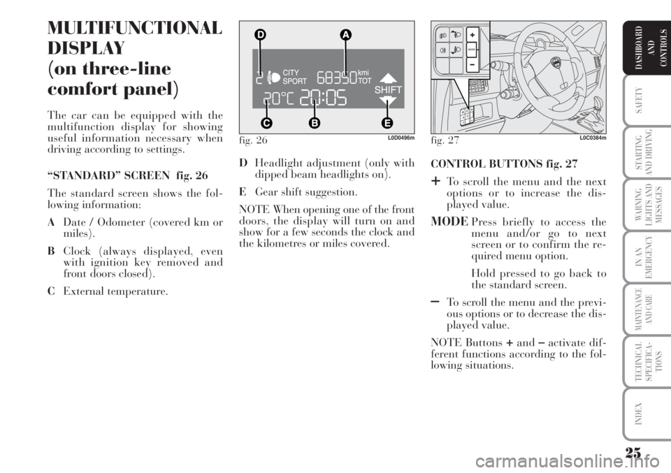
“STANDARD” SCREEN fig. 26
The standard screen shows the fol-
lowing information:
ADate / Odometer (covered km or
miles).
BClock (always displayed, even
with ignition key removed and
front doors closed).
CExternal temperature. CONTROL BUTTONS fig. 27
+To scroll the menu and the next
options or to increase the dis-
played value.
MODEPress briefly to access the
menu and/or go to next
screen or to confirm the re-
quired menu option.
Hold pressed to go back to
the standard screen.
–To scroll the menu and the previ-
ous options or to decrease the dis-
played value.
NOTE Buttons
+and–activate dif-
ferent functions according to the fol-
lowing situations. DHeadlight adjustment (only with
dipped beam headlights on).
EGear shift suggestion.
NOTE When opening one of the front
doors, the display will turn on and
show for a few seconds the clock and
the kilometres or miles covered.
fig. 27L0C0384m
Page 27 of 218
26
SAFETY
STARTING
AND DRIVING
WARNING
LIGHTS AND
MESSAGES
IN AN
EMERGENCY
MAINTENANCE
AND CARE
TECHNICAL
SPECIFICA-
TIONS
INDEX
DASHBOARD
AND
CONTROLS
Headlight adjustment (only
with dipped beam headlights on).
– when the standard page is dis-
played, this is used to adjust the head-
lights (see the “Headlights” para-
graph in this chapter).
Set-up menu
– for scrolling the menu up and down;
–to increase or decrease values during
settings.
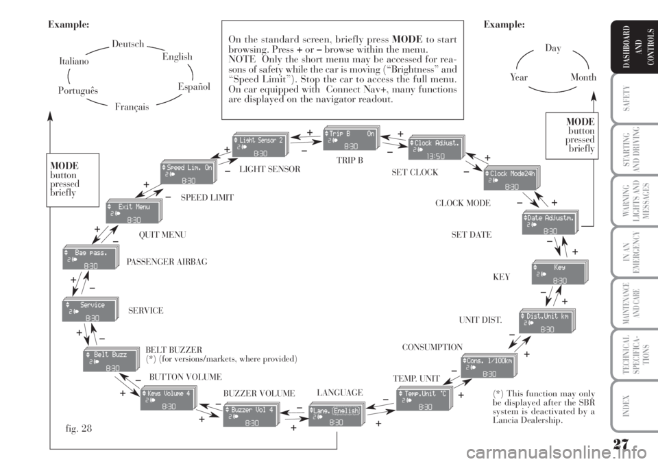
SET-UP MENU Fig. 28
The menu comprises a series of func-
tions arranged in a “circular fashion”
which can be selected through buttons
+and–to access the different select
operations and settings (setup) given
in the following paragraphs.
The setup menu is activated by press-
ing briefly button MODE.
Single presses on buttons
+and–will scroll the setup menu options.
Handling modes are different accord-
ing to the characteristic of the option
selected.Selecting “Date” and “Clock”:
– briefly press button MODEto select
the first value to be changed (e.g.
hours /minutes or year / month /
day).
– press buttons
+and–(by single
presses) to select the new setting;
– briefly press button MODEto store
the new setting and go to the next
setup menu option: if this is the last
one you will go back to the previously
selected option of the main menu.
Hold the
button MODE pressed to:
– quit set-up and to save only the
changes stored by the user (and con-
firmed by pressing button MODE).
The setup menu environment is
timed. Only the changes saved by the
user by briefly pressing MODE).ill be
saved when the menu is automatically
closed. NOTE Only the following functions
can be adjusted/set on the Instrument
Panel display if the Connect Nav+
system is present: “Lights”, “Speed
limit”, “Light sensor” (for versions/
markets, where provided), “Belt
buzzer” and “Passenger airbag”. The
other functions are shown on the
Connect Nav+ system display. Set and
adjustment them there.
Selecting a menu option
– briefly press button MODEto se-
lect the menu option that needs to be
changed.
– press buttons
+and–(by single
presses) to select the new setting;
– briefly press button MODEto store
the new setting and at the same time
go back to the previously selected
menu option.
Page 28 of 218
27
SAFETY
STARTING
AND DRIVING
WARNING
LIGHTS AND
MESSAGES
IN AN
EMERGENCY
MAINTENANCE
AND CARE
TECHNICAL
SPECIFICA-
TIONS
INDEX
DASHBOARD
AND
CONTROLS
Day
Ye a rMonth Example:
CONSUMPTION QUIT MENU SPEED LIMIT SET CLOCK LIGHT SENSOR TRIP B
CLOCK MODE
SET DATE
KEY
UNIT DIST.
BUTTON VOLUME
BUZZER VOLUME SERVICE
LANGUAGETEMP. UNIT
Example:
– +
+– – –
+ +
–
–
+
+++
–––
+ +
–
MODE
button
pressed
briefly
On the standard screen, briefly press MODEto start
browsing. Press +or–browse within the menu.
NOTE Only the short menu may be accessed for rea-
sons of safety while the car is moving (“Brightness” and
“Speed Limit”). Stop the car to access the full menu.
On car equipped with Connect Nav+, many functions
are displayed on the navigator readout.
–
+ +
–
MODE
button
pressed
briefly
Deutsch
English
Español
Italiano
Português
Français
(*) This function may only
be displayed after the SBR
system is deactivated by a
Lancia Dealership.
fig. 28
+
– +
–+
–
+
–
+ –
BELT BUZZER
(*) (for versions/markets, where provided) PASSENGER AIRBAG
Page 30 of 218
29
SAFETY
STARTING
AND DRIVING
WARNING
LIGHTS AND
MESSAGES
IN AN
EMERGENCY
MAINTENANCE
AND CARE
TECHNICAL
SPECIFICA-
TIONS
INDEX
DASHBOARD
AND
CONTROLS
Adjusting the automatic
headlight sensor sensitivity
(light sensor)
(for versions/markets, where provided)
This function is used to adjust the
dusk sensor sensitivity to three levels
(level 1 = minimum, level 2 =
medium, level 3 = maximum); higher
the sensitivity, lower the quantity of
external light needed to switch the
headlights on. The device is set to
level “2” when the car is delivered.
Proceed as follows to set:
– briefly press button MODE, the pre-
viously set level will flash on the dis-
play;
– press button +or–for setting;
– briefly press button MODEto go
back to the menu screen or hold the
button pressed to go back to the stan-
dard screen without storing the set-
tings.Turning Trip B on/off (Trip B)
This function may be used to activate
(On) or deactivate (Off) the Trip B
(partial trip).
For further information see “Trip
computer”.
Proceed as follows to turn on and off:
– briefly pressMODEON or OFF
flashes on the display (according to
the previous setting);
– press button +or–for setting;
– briefly press button MODEto go
back to the menu screen or hold the
button pressed to go back to the stan-
dard screen without storing the set-
tings.Setting the clock
(Set clock)
This function is used to set the clock.
To carry out the adjustment, proceed
as follows:
– briefly press button MODE: the
“hours” will flash on the display;
– press button +or–to set;
– briefly press button MODE: “min-
utes” will start flashing on the display;
– press button +or–to set;
NOTE The setting will increase or de-
crease by one unit each time +or–is
pressed. Hold the button pressed to
increase/decrease the setting rapidly.
Complete the setting by briefly press-
ing the button when you approach the
required setting.
– briefly press button MODEto go
back to the menu screen or hold the
button pressed to go back to the stan-
dard screen without storing the set-
tings.
Page 31 of 218
30
SAFETY
STARTING
AND DRIVING
WARNING
LIGHTS AND
MESSAGES
IN AN
EMERGENCY
MAINTENANCE
AND CARE
TECHNICAL
SPECIFICA-
TIONS
INDEX
DASHBOARD
AND
CONTROLS
Unlocking the doors and the
tailgate (key)
This function is used to: unlock the
front and rear doors, unlock the dri-
ver’s side door or all the doors includ-
ing the tailgate.
Proceed as follows to set:
– briefly press button MODE: “Open
doors”, “Open driver”, “Open all”;
– press button +or–to select. The se-
lected item will blink.
– briefly press button MODEto go
back to the menu screen or hold the
button pressed to go back to the stan-
dard screen without storing the set-
tings. – briefly press MODE: “month” will
start flashing on the display;
– press button +or–to set;
– briefly press button MODE: “day”
will start flashing on the display;
– press button +or–to set.
Note The setting will increase or de-
crease by one unit each time +or–is
pressed. Hold the button pressed to in-
crease/decrease the setting rapidly.
Complete the setting by briefly press-
ing the button when you approach the
required setting.
– briefly press button MODEto go
back to the menu screen or hold the
button pressed to go back to the stan-
dard screen without storing the set-
tings. 12h/24h clock mode
This function is used to select 12h or
24 h display.
To carry out the adjustment, proceed
as follows:
–briefly pressMODE: either 12h or
24h will start flashing on the display
(according to the previous setting);
– press button +or–for setting;
– briefly press button MODEto go
back to the menu screen or hold the
button pressed to go back to the stan-
dard screen without storing the set-
tings.
Set date
This function is used to set the date
(year – month – day).
Proceed as follows to update:
– briefly press button MODE: “year”
will start flashing on the display;
– press +or–to adjust;
Page 39 of 218
38
SAFETY
STARTING
AND DRIVING
WARNING
LIGHTS AND
MESSAGES
IN AN
EMERGENCY
MAINTENANCE
AND CARE
TECHNICAL
SPECIFICA-
TIONS
INDEX
DASHBOARD
AND
CONTROLS
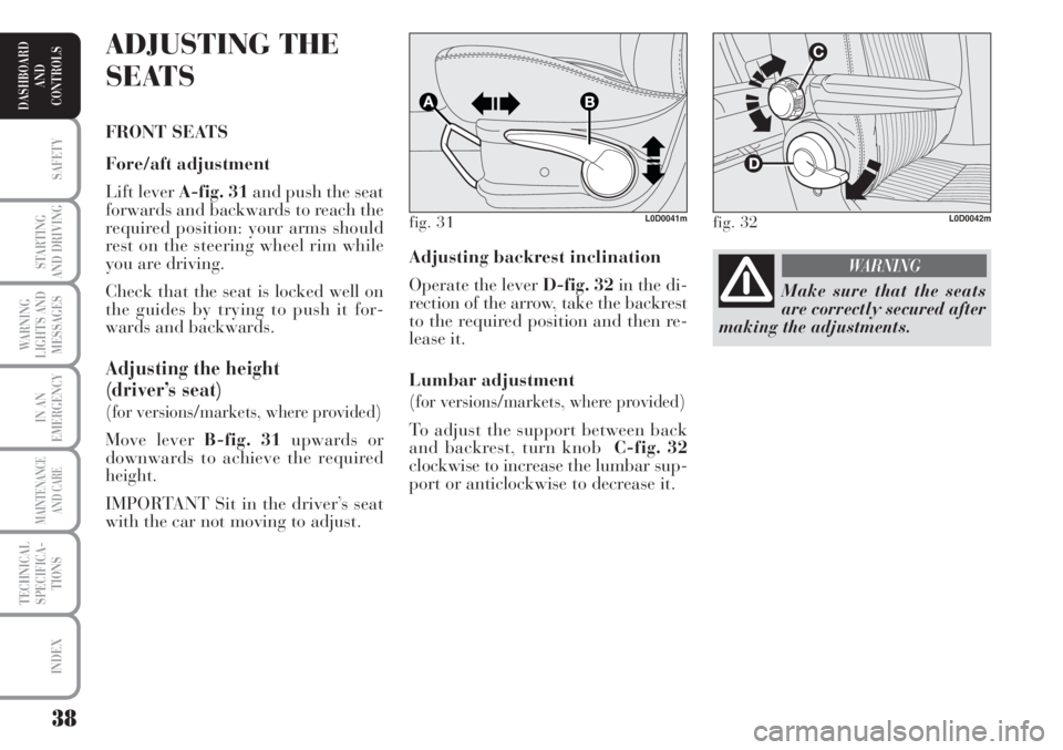
Adjusting backrest inclination
Operate the lever D-fig. 32in the di-
rection of the arrow, take the backrest
to the required position and then re-
lease it.
Lumbar adjustment
(for versions/markets, where provided)
To adjust the support between back
and backrest, turn knob C-fig. 32
clockwise to increase the lumbar sup-
port or anticlockwise to decrease it.
ADJUSTING THE
SEATS
FRONT SEATS
Fore/aft adjustment
Lift lever A-fig. 31and push the seat
forwards and backwards to reach the
required position: your arms should
rest on the steering wheel rim while
you are driving.
Check that the seat is locked well on
the guides by trying to push it for-
wards and backwards.
Adjusting the height
(driver’s seat)
(for versions/markets, where provided)
Move lever B-fig. 31upwards or
downwards to achieve the required
height.
IMPORTANT Sit in the driver’s seat
with the car not moving to adjust.
fig. 31L0D0041mfig. 32L0D0042m
Make sure that the seats
are correctly secured after
making the adjustments.
WARNING