Lancia Voyager 2012 Owner handbook (in English)
Manufacturer: LANCIA, Model Year: 2012, Model line: Voyager, Model: Lancia Voyager 2012Pages: 344, PDF Size: 3.95 MB
Page 161 of 344
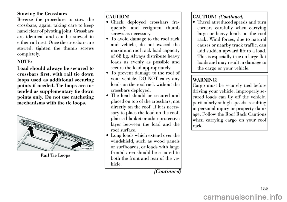
Stowing the Crossbars
Reverse the procedure to stow the
crossbars, again, taking care to keep
hand clear of pivoting joint. Crossbars
are identical and can be stowed in
either rail nest. Once the crossbars are
stowed, tighten the thumb screws
completely.
NOTE:
Load should always be secured to
crossbars first, with rail tie down
loops used as additional securing
points if needed. Tie loops are in-
tended as supplementary tie down
points only. Do not use ratcheting
mechanisms with the tie loops.
CAUTION!
Check deployed crossbars fre-quently and retighten thumb
screws as necessary.
To avoid damage to the roof rack
and vehicle, do not exceed the
maximum roof rack load capacity
of 68 kg. Always distribute heavy
loads as evenly as possible and
secure the load appropriately.
To prevent damage to the roof of
your vehicle, DO NOT carry any
loads on the roof rack without the
crossbars deployed.
The load should be secured and
placed on top of the crossbars, not
directly on the roof. If it is neces-
sary to place the load on the roof,
place a blanket or other protective
layer between the load and the
roof surface.
Long loads which extend over the
windshield, such as wood panels
or surfboards, or loads with large
frontal area should be secured to
both the front and rear of the ve-
hicle.
(Continued)
CAUTION!(Continued)
Travel at reduced speeds and turn
corners carefully when carrying
large or heavy loads on the roof
rack. Wind forces, due to natural
causes or nearby truck traffic, can
add sudden upward lift to a load.
This is especially true on large flat
loads and may result in damage to
the cargo or your vehicle.WARNING!
Cargo must be securely tied before
driving your vehicle. Improperly se-
cured loads can fly off the vehicle,
particularly at high speeds, resulting
in personal injury or property dam-
age. Follow the Roof Rack Cautions
when carrying cargo on your roof
rack.
Rail Tie Loops
155
Page 162 of 344
SUN SCREENS (for
versions/markets, where
provided)
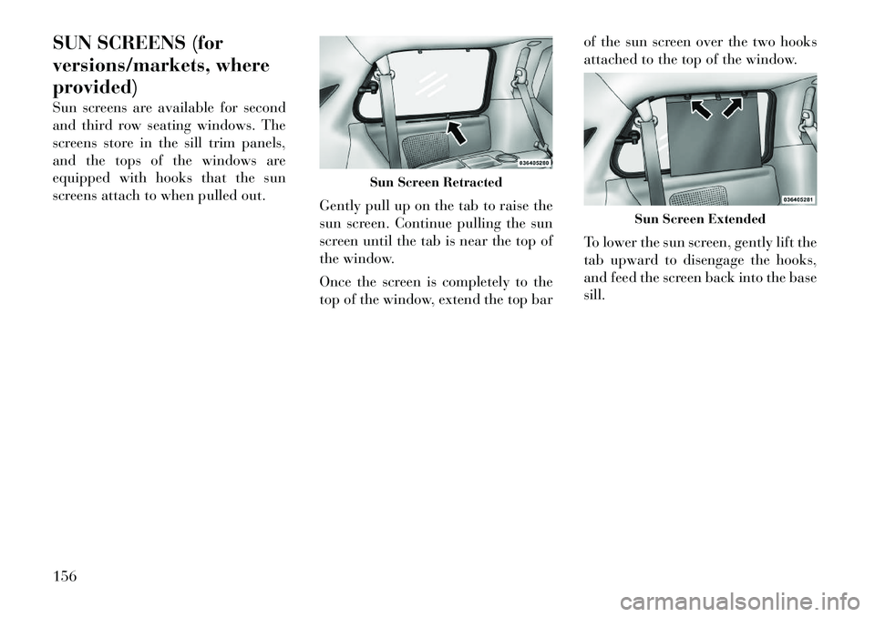
Sun screens are available for second
and third row seating windows. The
screens store in the sill trim panels,
and the tops of the windows are
equipped with hooks that the sun
screens attach to when pulled out.Gently pull up on the tab to raise the
sun screen. Continue pulling the sun
screen until the tab is near the top of
the window.
Once the screen is completely to the
top of the window, extend the top barof the sun screen over the two hooks
attached to the top of the window.
To lower the sun screen, gently lift the
tab upward to disengage the hooks,
and feed the screen back into the base
sill.
Sun Screen Retracted
Sun Screen Extended
156
Page 163 of 344

4
UNDERSTANDING YOUR INSTRUMENT
PANEL
INSTRUMENT PANEL FEATURES . . . . . . . . . . . 161
INSTRUMENT CLUSTER — GASOLINE . . . . . . 162
INSTRUMENT CLUSTER — DIESEL . . . . . . . . . 163
INSTRUMENT CLUSTER DESCRIPTIONS . . . . 164
COMPASS MINI-TRIP COMPUTER (CMTC) (for versions/markets, where provided) . . . . . . . 170
RESET BUTTONS . . . . . . . . . . . . . . . . . . . . . 170
COMPASS/TEMPERATURE DISPLAY . . . . . . 170
ELECTRONIC VEHICLE INFORMATION CENTER (EVIC) (for versions/markets, where
provided) . . . . . . . . . . . . . . . . . . . . . . . . . . . . . . 172
ELECTRONIC VEHICLE INFORMATION CENTER (EVIC) DISPLAYS . . . . . . . . . . . . . . 173
EVIC WHITE TELLTALE LIGHTS . . . . . . . . . 175
EVIC AMBER TELLTALE LIGHTS . . . . . . . . . 176
EVIC RED TELLTALE LIGHTS . . . . . . . . . . . 176
OIL CHANGE DUE . . . . . . . . . . . . . . . . . . . . . 178
FUEL ECONOMY . . . . . . . . . . . . . . . . . . . . . . 178
VEHICLE SPEED . . . . . . . . . . . . . . . . . . . . . . 179
TRIP INFO . . . . . . . . . . . . . . . . . . . . . . . . . . . 179
TIRE BAR . . . . . . . . . . . . . . . . . . . . . . . . . . . 179
157
Page 164 of 344
VEHICLE INFO (CUSTOMERINFORMATION FEATURES) . . . . . . . . . . . . . . 180
MESSAGES . . . . . . . . . . . . . . . . . . . . . . . . . . 180
UNITS . . . . . . . . . . . . . . . . . . . . . . . . . . . . . . 180
KEYLESS ENTER-N-GO DISPLAY (for versions/markets, where provided) . . . . . . . . 180
COMPASS / TEMPERATURE DISPLAY . . . . . 180
CUSTOMER-PROGRAMMABLE FEATURES (SYSTEM SETUP) . . . . . . . . . . . . . . . . . . . . . 183
SOUND SYSTEMS . . . . . . . . . . . . . . . . . . . . . . . 187
NAVIGATION SYSTEM (for versions/markets, where provided) . . . . . . . . . . . . . . . . . . . . . . . . . 187
iPod®/USB/MP3 CONTROL (for versions/ markets, where equipped) . . . . . . . . . . . . . . . . . 187
Connecting The iPod® Or External USB Device . . . . . . . . . . . . . . . . . . . . . . . . . . . . . . 188
Using This Feature . . . . . . . . . . . . . . . . . . . . . 188
Controlling The iPod® Or External USB Device Using Radio Buttons . . . . . . . . . . . . . . 188
Play Mode . . . . . . . . . . . . . . . . . . . . . . . . . . . 188
List Or Browse Mode . . . . . . . . . . . . . . . . . . . 189
Bluetooth Streaming Audio (BTSA) . . . . . . . . 191
UCONNECT™ MULTIMEDIA VIDEO ENTERTAINMENT SYSTEM (VES)™ (for
versions/markets, where provided) . . . . . . . . . . 191
Getting Started . . . . . . . . . . . . . . . . . . . . . . . . 191
Play Video Games . . . . . . . . . . . . . . . . . . . . . 192
158
Page 165 of 344
Listen To An Audio Source On Channel 2While A Video Is Playing On Channel 1 . . . . . 192
Dual Video Screen . . . . . . . . . . . . . . . . . . . . . 193
Play A DVD Using The Touch-Screen Radio . . . . . . . . . . . . . . . . . . . . . . . . . . . . . . . 193
Play A DVD Using The VES™ Player (for versions/markets, where provided) . . . . . . . . 194
Listen To An Audio Source While A Video Is Playing . . . . . . . . . . . . . . . . . . . . . . . . . . . . . 195
Third Row Swivel Screen (for versions/ markets, where provided) . . . . . . . . . . . . . . . 196
Important Notes For Dual Video Screen System . . . . . . . . . . . . . . . . . . . . . . . . . . . . . . 196
Remote Control . . . . . . . . . . . . . . . . . . . . . . . 196
Remote Control Storage . . . . . . . . . . . . . . . . . 198
Locking The Remote Control . . . . . . . . . . . . . 198
Replacing The Remote Control Batteries . . . . 198
Headphones Operation . . . . . . . . . . . . . . . . . 198
Controls . . . . . . . . . . . . . . . . . . . . . . . . . . . . . 199
Replacing The Headphone Batteries . . . . . . . 199
Unwired® Stereo Headphone Lifetime Limited Warranty . . . . . . . . . . . . . . . . . . . . . 200
System Information . . . . . . . . . . . . . . . . . . . . 200
STEERING WHEEL AUDIO CONTROLS (for versions/markets, where provided) . . . . . . . . . . 207
Radio Operation . . . . . . . . . . . . . . . . . . . . . . 208
159
Page 166 of 344

CD Player . . . . . . . . . . . . . . . . . . . . . . . . . . . 208
CD/DVD DISC MAINTENANCE . . . . . . . . . . . . . 208
RADIO OPERATION AND MOBILE PHONES . . . 208
CLIMATE CONTROLS . . . . . . . . . . . . . . . . . . . . 209 MANUAL HEATING AND AIRCONDITIONING SYSTEM (for
versions/markets, where provided) . . . . . . . . 209
REAR MANUAL CLIMATE CONTROL (for versions/markets, where provided) . . . . . . . . 212
AUTOMATIC TEMPERATURE CONTROL (ATC) (for versions/markets, where
provided) . . . . . . . . . . . . . . . . . . . . . . . . . . . . 213
SUMMER OPERATION . . . . . . . . . . . . . . . . . 220
WINTER OPERATION . . . . . . . . . . . . . . . . . . 220
VACATION/STORAGE . . . . . . . . . . . . . . . . . . 220
WINDOW FOGGING . . . . . . . . . . . . . . . . . . . 220
OUTSIDE AIR INTAKE . . . . . . . . . . . . . . . . . 220
OPERATING TIPS . . . . . . . . . . . . . . . . . . . . . 220
A/C AIR FILTER . . . . . . . . . . . . . . . . . . . . . . 220
160
Page 167 of 344

INSTRUMENT PANEL FEATURES1 — Air Vents5 — Analog Clock9 — DVD (for versions/
markets, where provided) 13 — Ignition Switch
2 — Instrument Cluster 6 — Upper Glove
Compartment10 — Storage Bin
14 — Hood Release
3 — Shift Lever 7 — Lower Glove
Compartment11 — Cup Holders
15 — Dimmer Switch
4 — Radio 8 — Climate Controls 12 — Switch Bank 16 — Headlight Switch
161
Page 168 of 344
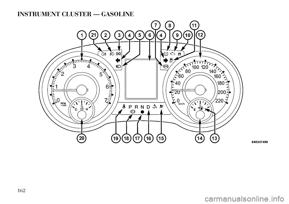
INSTRUMENT CLUSTER — GASOLINE162
Page 169 of 344
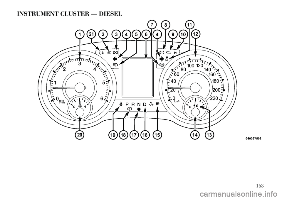
INSTRUMENT CLUSTER — DIESEL
163
Page 170 of 344
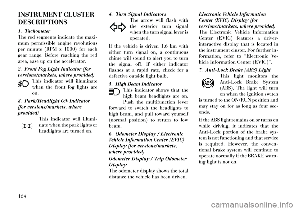
INSTRUMENT CLUSTER
DESCRIPTIONS
1. Tachometer
The red segments indicate the maxi-
mum permissible engine revolutions
per minute (RPM x 1000) for each
gear range. Before reaching the red
area, ease up on the accelerator.
2. Front Fog Light Indicator (for
versions/markets, where provided)This indicator will illuminate
when the front fog lights are
on.
3. Park/Headlight ON Indicator
(for versions/markets, where
provided) This indicator will illumi-
nate when the park lights or
headlights are turned on. 4. Turn Signal Indicators
The arrow will flash with
the exterior turn signal
when the turn signal lever is
operated.
If the vehicle is driven 1.6 km with
either turn signal on, a continuous
chime will sound to alert you to turn
the signal off. If either indicator
flashes at a rapid rate, check for a
defective outside light bulb.
5. High Beam Indicator This indicator shows that the
high beam headlights are on.
Push the multifunction lever
forward to switch the headlights to
high beam, and pull toward yourself
(normal position) to return to low
beam.
6. Odometer Display / Electronic
Vehicle Information Center (EVIC)
Display (for versions/markets,
where provided)
Odometer Display / Trip Odometer
Display
The odometer display shows the total
distance the vehicle has been driven. Electronic Vehicle Information
Center (EVIC) Display (for
versions/markets, where provided)
The Electronic Vehicle Information
Center (EVIC) features a driver-
interactive display that is located in
the instrument cluster. For further in-
formation, refer to “Electronic Ve-
hicle Information Center (EVIC)”.
7. Anti-Lock Brake (ABS) Light
This light monitors the
Anti-Lock Brake System
(ABS). The light will turn
on when the ignition switch
is turned to the ON/RUN position and
may stay on for as long as four sec-
onds.
If the ABS light remains on or turns on
while driving, it indicates that the
Anti-Lock portion of the brake sys-
tem is not functioning and that service
is required. However, the conven-
tional brake system will continue to
operate normally if the BRAKE warn-
ing light is not on.164