Lancia Voyager 2013 Owner handbook (in English)
Manufacturer: LANCIA, Model Year: 2013, Model line: Voyager, Model: Lancia Voyager 2013Pages: 360, PDF Size: 4.21 MB
Page 141 of 360
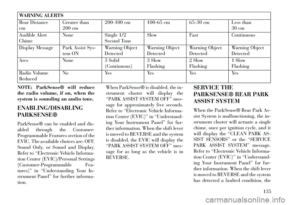
WARNING ALERTS
Rear Distance
cmGreater than
200 cm200-100 cm 100-65 cm 65-30 cm Less than
30 cm
Audible Alert
Chime None
Single 1/2
Second Tone Slow
FastContinuous
Display Message Park Assist Sys- tem ONWarning Object
DetectedWarning Object
DetectedWarning Object
DetectedWarning Object
Detected
Arcs None3 Solid
(Continuous) 3 Slow
Flashing2 Slow
Flashing1 Slow
Flashing
Radio Volume
Reduced No
YesYesYesYes
NOTE: ParkSense® will reduce
the radio volume, if on, when the
system is sounding an audio tone.
ENABLING/DISABLING
PARKSENSE®
ParkSense® can be enabled and dis-
abled through the Customer-
Programmable Features section of the
EVIC. The available choices are: OFF,
Sound Only, or Sound and Display.
Refer to “Electronic Vehicle Informa-
tion Center (EVIC)/Personal Settings
(Customer-Programmable Fea-
tures)” in “Understanding Your In-
strument Panel” for further informa-
tion. When ParkSense® is disabled, the in-
strument cluster will display the
“PARK ASSIST SYSTEM OFF” mes-
sage for approximately five seconds.
Refer to “Electronic Vehicle Informa-
tion Center (EVIC)” in “Understand-
ing Your Instrument Panel” for fur-
ther information. When the shift lever
is moved to REVERSE and the system
is disabled, the EVIC will display the
“PARK ASSIST SYSTEM OFF” mes-
sage for as long as the vehicle is in
REVERSE.
SERVICE THE
PARKSENSE® REAR PARK
ASSIST SYSTEM
When the ParkSense® Rear Park As-
sist System is malfunctioning, the in-
strument cluster will actuate a single
chime, once per ignition cycle, and it
will display the “CLEAN PARK AS-
SIST SENSORS” or the “SERVICE
PARK ASSIST SYSTEM” message.
Refer to “Electronic Vehicle Informa-
tion Center (EVIC)” in “Understand-
ing Your Instrument Panel” for fur-
ther information. When the shift lever
is moved to REVERSE and the system
has detected a faulted condition, the
135
Page 142 of 360
EVIC will display the “CLEAN PARK
ASSIST SENSORS” or the “SER-
VICE PARK ASSIST SYSTEM” mes-
sage for as long as the vehicle is in
REVERSE. Under this condition,
ParkSense® will not operate.
If “CLEAN PARK ASSIST SEN-
SORS” appears in the EVIC after
making sure the rear fascia/bumper is
free from snow, ice, mud, dirt or other
obstruction, see your authorized
dealer.
If “SERVICE PARK ASSIST SYS-
TEM” appears in the EVIC, see your
authorized dealer.
CLEANING THE
PARKSENSE® SYSTEM
Clean the ParkSense® sensors with
water, car wash soap and a soft cloth.
Do not use rough or hard cloths. Do
not scratch or poke the sensors. Oth-
erwise, you could damage the sensors.PARKSENSE® SYSTEM
USAGE PRECAUTIONS
NOTE:
Ensure that the rear bumper is
free of snow, ice, mud, dirt and
debris to keep the ParkSense®
system operating properly.
Jackhammers, large trucks, and other vibrations could affect the
performance of ParkSense®.
When you turn ParkSense® off, the instrument cluster will dis-
play “PARK ASSIST SYSTEM
OFF.” Furthermore, once you
turn ParkSense® off, it remains
off until you turn it on again,
even if you cycle the ignition key.
When you move the shift lever to the REVERSE position and
ParkSense® is turned off, the
EVIC will display “PARK AS-
SIST SYSTEM OFF” message for
as long as the vehicle is in
REVERSE. ParkSense®, when on, will re-
duce the radio volume when it is
sounding a tone.
Clean the ParkSense® sensors regularly, taking care not to
scratch or damage them. The
sensors must not be covered
with ice, snow, slush, mud, dirt
or debris. Failure to do so can
result in the system not working
properly. The ParkSense® sys-
tem might not detect an obstacle
behind the fascia/bumper, or it
could provide a false indication
that an obstacle is behind the
fascia/bumper.
Objects such as bicycle carriers, trailer hitches, etc., must not be
placed within 30 cm from the
rear fascia/bumper while driv-
ing the vehicle. Failure to do so
can result in the system misin-
terpreting a close object as a
sensor problem, causing the
“SERVICE PARK ASSIST SYS-
TEM” message to be displayed
in the EVIC.
136
Page 143 of 360

On vehicles equipped with atailgate, ParkSense® should be
disabled when the tailgate is in
the lowered or open position
and the vehicle is in REVERSE.
A lowered tailgate could provide
a false indication that an ob-
stacle is behind the vehicle.CAUTION!
ParkSense® is only a parking aidand it is unable to recognize every
obstacle, including small ob-
stacles. Parking curbs might be
temporarily detected or not de-
tected at all. Obstacles located
above or below the sensors will
not be detected when they are in
close proximity.
The vehicle must be driven slowly when using ParkSense® in order
to be able to stop in time when an
obstacle is detected. It is recom-
mended that the driver looks over
his/her shoulder when using
ParkSense®.
WARNING!
Drivers must be careful whenbacking up even when using the
Rear Park Assist system. Always
check carefully behind your ve-
hicle, look behind you, and be
sure to check for pedestrians, ani-
mals, other vehicles, obstruc-
tions, and blind spots before
backing up. You are responsible
for safety and must continue to
pay attention to your surround-
ings. Failure to do so can result in
serious injury or death.
(Continued)
WARNING!(Continued)
Before using the Rear Park Assist system, it is strongly recom-
mended that the ball mount and
hitch ball assembly is discon-
nected from the vehicle when the
vehicle is not used for towing.
Failure to do so can result in in-
jury or damage to vehicles or ob-
stacles because the hitch ball will
be much closer to the obstacle
than the rear fascia when the
loudspeaker sounds the continu-
ous tone. Also, the sensors could
detect the ball mount and hitch
ball assembly, depending on its
size and shape, giving a false in-
dication that an obstacle is be-
hind the vehicle.
137
Page 144 of 360

PARKVIEW® REAR
BACK UP CAMERA (for
versions/markets, where
provided)
Your vehicle may be equipped with
the ParkView® Rear Back Up Cam-
era that allows you to see an on-screen
image of the rear surroundings of
your vehicle whenever the shift lever
is put into REVERSE. The image will
be displayed on the Navigation/Multimedia radio display screen along
with a caution note to “check entire
surroundings” across the top of the
screen. After five seconds this note
will disappear. The ParkView® cam-
era is located on the rear of the vehicle
above the rear License plate.
When the vehicle is shifted out of RE-
VERSE, the rear camera mode is ex-
ited and the navigation or audio
screen appears again.
When displayed, static grid lines will
illustrate the width of the vehicle
while a dashed center-line will indi-
cate the center of the vehicle to assist
with aligning to a hitch/receiver. The
static grid lines will show separate
zones that will help indicate the dis-
tance to the rear of the vehicle. The
following table shows the approxi-
mate distances for each zone:Zone
Distance to the rear of the vehicle
Red 0 - 30 cm
Yellow 30 cm - 1 m
Green 1 m or greaterWARNING!
Drivers must be careful when back-
ing up even when using the
ParkView® Rear Back Up Camera.
Always check carefully behind your
vehicle, and be sure to check for
pedestrians, animals, other ve-
hicles, obstructions, or blind spots
(Continued)
WARNING!(Continued)
before backing up. You are respon-
sible for the safety of your sur-
roundings and must continue to
pay attention while backing up.
Failure to do so can result in serious
injury or death.
CAUTION!
To avoid vehicle damage,
ParkView® should only be used as
a parking aid. The camera is un-
able to view every obstacle or ob-
ject in your drive path.
(Continued)
138
Page 145 of 360
CAUTION!(Continued)
To avoid vehicle damage, the ve- hicle must be driven slowly when
using ParkView® to be able to
stop in time when an obstacle is
seen. It is recommended that the
driver look frequently over his/
her shoulder when using
ParkView®.
NOTE: If snow, ice, mud, or any
foreign substance builds up on the
camera lens, clean the lens, rinse
with water, and dry with a soft
cloth. Do not cover the lens.
TURNING PARKVIEW® ON
OR OFF — WITH
NAVIGATION/
MULTIMEDIA RADIO
1. Press the “menu” hard-key.
2. Select “system setup” soft-key.
3. Press the “camera setup” soft-key.
4. Enable or disable the rear camera
feature by selecting “enable rear cam-
era in reverse” soft-key. 5. Press the “save” soft-key.
TURNING PARKVIEW® ON
OR OFF — WITHOUT
NAVIGATION/
MULTIMEDIA RADIO
1. Press the “menu” hard-key.
2. Select “system setup” soft-key.
3. Enable or disable the rear camera
feature by selecting “enable rear cam-
era in reverse” soft-key.
OVERHEAD CONSOLES
FRONT OVERHEAD
CONSOLE
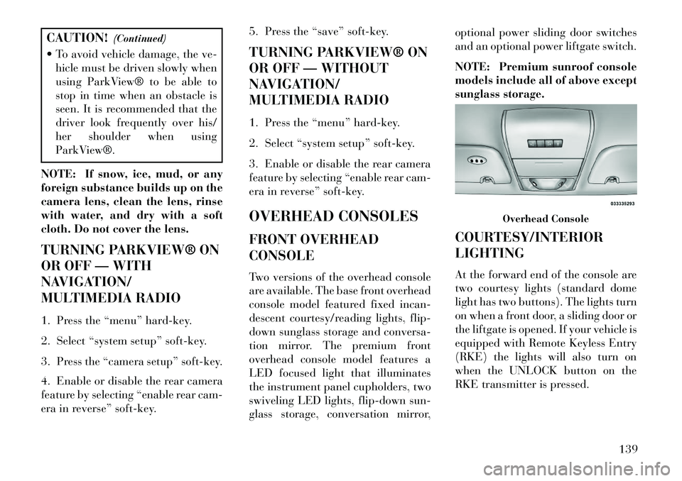
Two versions of the overhead console
are available. The base front overhead
console model featured fixed incan-
descent courtesy/reading lights, flip-
down sunglass storage and conversa-
tion mirror. The premium front
overhead console model features a
LED focused light that illuminates
the instrument panel cupholders, two
swiveling LED lights, flip-down sun-
glass storage, conversation mirror,optional power sliding door switches
and an optional power liftgate switch.
NOTE: Premium sunroof console
models include all of above except
sunglass storage.
COURTESY/INTERIOR
LIGHTING
At the forward end of the console are
two courtesy lights (standard dome
light has two buttons). The lights turn
on when a front door, a sliding door or
the liftgate is opened. If your vehicle is
equipped with Remote Keyless Entry
(RKE) the lights will also turn on
when the UNLOCK button on the
RKE transmitter is pressed.
Overhead Console
139
Page 146 of 360
The courtesy lights also function as
reading lights. Press in on each lens to
turn these lights on while inside the
vehicle. Press a second time to turn
each light off. You may adjust the
direction of these lights by pressing
the outside ring, which is identified
with four directional arrows (LED
lamps only).
The area around the instrument panel
cupholders is also illuminated from a
light in the overhead console (pre-
mium console only). This light is
turned on when the headlight switch
is on, and will adjust in brightness
when the dimmer control is rotated up
or down.
SUNGLASS STORAGE
(NON-SUNROOF ONLY)
At the front of the overhead console, a
compartment is provided for the stor-
age of two pairs of sunglasses.
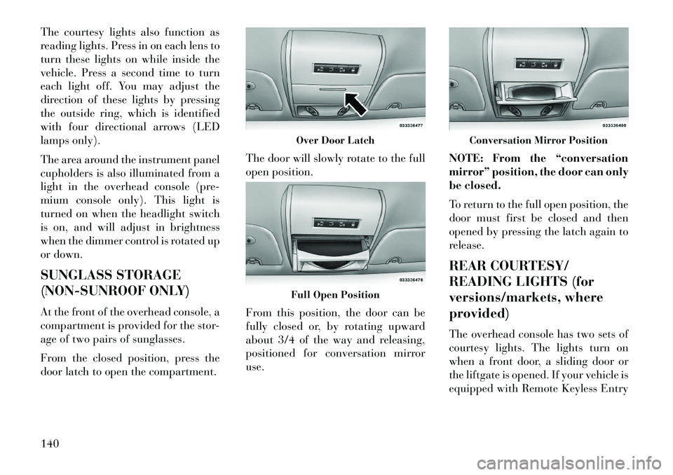
From the closed position, press the
door latch to open the compartment.The door will slowly rotate to the full
open position.
From this position, the door can be
fully closed or, by rotating upward
about 3/4 of the way and releasing,
positioned for conversation mirror
use.
NOTE: From the “conversation
mirror” position, the door can only
be closed.
To return to the full open position, the
door must first be closed and then
opened by pressing the latch again to
release.
REAR COURTESY/
READING LIGHTS (for
versions/markets, where
provided)
The overhead console has two sets of
courtesy lights. The lights turn on
when a front door, a sliding door or
the liftgate is opened. If your vehicle is
equipped with Remote Keyless Entry
Over Door LatchFull Open Position
Conversation Mirror Position
140
Page 147 of 360
(RKE) the lights will also turn on
when the UNLOCK button on the
RKE transmitter is pressed.
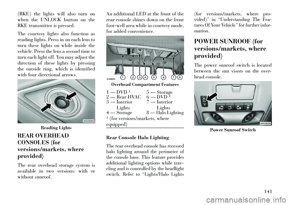
The courtesy lights also function as
reading lights. Press in on each lens to
turn these lights on while inside the
vehicle. Press the lens a second time to
turn each light off. You may adjust the
direction of these lights by pressing
the outside ring, which is identified
with four directional arrows.
REAR OVERHEAD
CONSOLES (for
versions/markets, where
provided)
The rear overhead storage system is
available in two versions: with or
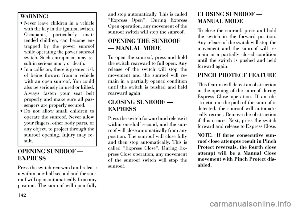
without sunroof.An additional LED at the front of the
rear console shines down on the front
foot-well area while in courtesy mode,
for added convenience.
Rear Console Halo Lighting
The rear overhead console has recessed
halo lighting around the perimeter of
the console base. This feature provides
additional lighting options while trav-
eling and is controlled by the headlight
switch. Refer to “Lights/Halo Lights
(for versions/markets, where pro-
vided)” in “Understanding The Fea-
tures Of Your Vehicle” for further infor-
mation.
POWER SUNROOF (for
versions/markets, where
provided)
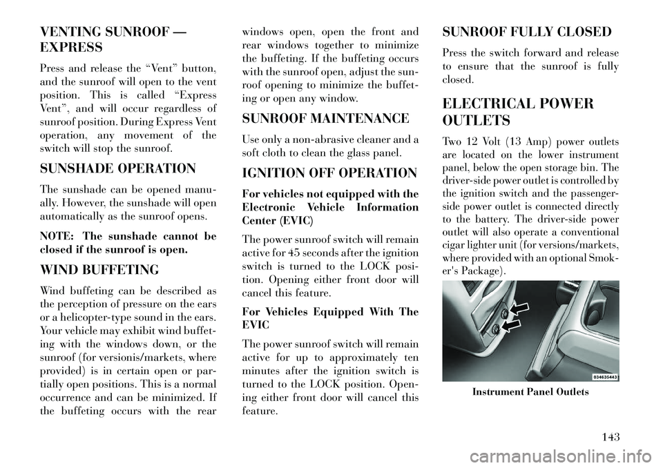
The power sunroof switch is located
between the sun visors on the over-
head console.
Reading Lights
Overhead Compartment Features
1 — DVD ¹ 5 — Storage
2 — Rear HVAC 6 — DVD ¹
3 — Interior
Lights 7 — Interior
Lights
4 — Storage
8 — Halo Lighting
¹ (for versions/markets, where
equipped)
Power Sunroof Switch
141
Page 148 of 360
WARNING!
Never leave children in a vehicle
with the key in the ignition switch.
Occupants, particularly unat-
tended children, can become en-
trapped by the power sunroof
while operating the power sunroof
switch. Such entrapment may re-
sult in serious injury or death. In a collision, there is greater riskof being thrown from a vehicle
with an open sunroof. You could
also be seriously injured or killed.
Always fasten your seat belt
properly and make sure all pas-
sengers are properly secured.
Do not allow small children to
operate the sunroof. Never allow
your fingers, other body parts, or
any object, to project through the
sunroof opening. Injury may re-
sult.
OPENING SUNROOF —
EXPRESS
Press the switch rearward and release
it within one-half second and the sun-
roof will open automatically from any
position. The sunroof will open fully and stop automatically. This is called
“Express Open”. During Express
Open operation, any movement of the
sunroof switch will stop the sunroof.
OPENING THE SUNROOF
— MANUAL MODE
To open the sunroof, press and hold
the switch rearward to full open. Any
release of the switch will stop the
movement and the sunroof will re-
main in a partially opened condition
until the switch is pushed and held
rearward again.
CLOSING SUNROOF —
EXPRESS
Press the switch forward and release it
within one-half second, and the sun-
roof will close automatically from any
position. The sunroof will close fully
and then stop automatically. This is
called “Express Close”. During Ex-
press Close operation, any movement
of the sunroof switch will stop the
sunroof.
CLOSING SUNROOF —
MANUAL MODE
To close the sunroof, press and hold
the switch in the forward position.
Any release of the switch will stop the
movement and the sunroof will re-
main in a partially closed condition
until the switch is pushed and held
forward again.
PINCH PROTECT FEATURE
This feature will detect an obstruction
in the opening of the sunroof during
Express Close operation. If an ob-
struction in the path of the sunroof is
detected, the sunroof will automati-
cally retract. Remove the obstruction
if this occurs. Next, press the switch
forward and release to Express Close.
NOTE: If three consecutive sun-
roof close attempts result in Pinch
Protect reversals, the fourth close
attempt will be a Manual Close
movement with Pinch Protect dis-
abled.
142
Page 149 of 360
VENTING SUNROOF —
EXPRESS
Press and release the “Vent” button,
and the sunroof will open to the vent
position. This is called “Express
Vent”, and will occur regardless of
sunroof position. During Express Vent
operation, any movement of the
switch will stop the sunroof.
SUNSHADE OPERATION
The sunshade can be opened manu-
ally. However, the sunshade will open
automatically as the sunroof opens.
NOTE: The sunshade cannot be
closed if the sunroof is open.
WIND BUFFETING
Wind buffeting can be described as
the perception of pressure on the ears
or a helicopter-type sound in the ears.
Your vehicle may exhibit wind buffet-
ing with the windows down, or the
sunroof (for versionis/markets, where
provided) is in certain open or par-
tially open positions. This is a normal
occurrence and can be minimized. If
the buffeting occurs with the rearwindows open, open the front and
rear windows together to minimize
the buffeting. If the buffeting occurs
with the sunroof open, adjust the sun-
roof opening to minimize the buffet-
ing or open any window.
SUNROOF MAINTENANCE
Use only a non-abrasive cleaner and a
soft cloth to clean the glass panel.
IGNITION OFF OPERATION
For vehicles not equipped with the
Electronic Vehicle Information
Center (EVIC)
The power sunroof switch will remain
active for 45 seconds after the ignition
switch is turned to the LOCK posi-
tion. Opening either front door will
cancel this feature.
For Vehicles Equipped With The
EVIC
The power sunroof switch will remain
active for up to approximately ten
minutes after the ignition switch is
turned to the LOCK position. Open-
ing either front door will cancel this
feature.
SUNROOF FULLY CLOSED
Press the switch forward and release
to ensure that the sunroof is fully
closed.
ELECTRICAL POWER
OUTLETS
Two 12 Volt (13 Amp) power outlets
are located on the lower instrument
panel, below the open storage bin. The
driver-side power outlet is controlled by
the ignition switch and the passenger-
side power outlet is connected directly
to the battery. The driver-side power
outlet will also operate a conventional
cigar lighter unit (for versions/markets,
where provided with an optional Smok-
er's Package).
Instrument Panel Outlets
143
Page 150 of 360

CAUTION!
Do not exceed the maximumpower of 160 Watts (13 Amps) at
12 Volts. If the 160 Watt (13
Amp) power rating is exceeded
the fuse protecting the system will
need to be replaced.
Power outlets are designed for ac- cessory plugs only. Do not insert
any other object in the power out-
lets as this will damage the outlet
and blow the fuse. Improper use
of the power outlet can cause
damage not covered by your New
Vehicle Limited Warranty.
One outlet in the removable floor con-
sole (for versions/markets, where pro-
vided) shares a fuse with the lower
outlet in the instrument panel and is
also connected to the battery. Do not
exceed a maximum power of 160
Watts (13 Amps) shared between the
lower panel outlet and the removable
floor console outlet. On vehicles equipped with the Super
Console the power outlets are located
under the retractable cover. To access
the power outlets push down on the
cover and slide it toward the instru-
ment panel.
Each of these outlets can support 160
Watts (13 Amps). Do not exceed 160
Watts (13 Amps) for each of these
outlets.The power outlets include tethered
caps, labeled with a key or battery
symbol indicating the power source.
The power outlet, located on the lower
instrument panel, is powered directly
from the battery. Items plugged into
this power outlet may discharge the
battery and/or prevent the engine
from starting.
Super Console OutletsSuper Console Outlets
Power Outlet Fuses
1 — M7 Fuse 20 A Yellow Power
Outlet
2 — M6 Fuse 20 A Yellow Cigar
Lighter Instrument Panel
3 — M36 Fuse 20 A Yellow Power
Outlet Instrument Panel or with
Console
144