LAND ROVER DISCOVERY 1999 Workshop Manual
DISCOVERY 1999
LAND ROVER
LAND ROVER
https://www.carmanualsonline.info/img/64/57247/w960_57247-0.png
LAND ROVER DISCOVERY 1999 Workshop Manual
Trending: set clock, coolant, change time, brake pads replacement, change language, dashboard, radiator cap
Page 151 of 1529
MAINTENANCE
10-28 PROCEDURES
Check – Height sensors
SLS height sensors
1.Check height sensors for condition and
security.
2.Check electrical harness for chafing and
damage.
Front and rear axle suspension links
Check
Rear suspension
Front suspension
1.Check condition of front and rear axle
suspension link mounting rubbers.
2.Check security of fixings.
+ TORQUE WRENCH SETTINGS,
Front suspension.
+ TORQUE WRENCH SETTINGS, Rear
suspension.
Page 152 of 1529
MAINTENANCE
PROCEDURES 10-29
Towing bracket
Check
1.Check security of towing bracket.
Page 153 of 1529
MAINTENANCE
10-30 PROCEDURES
Engine mountings - V8 engine
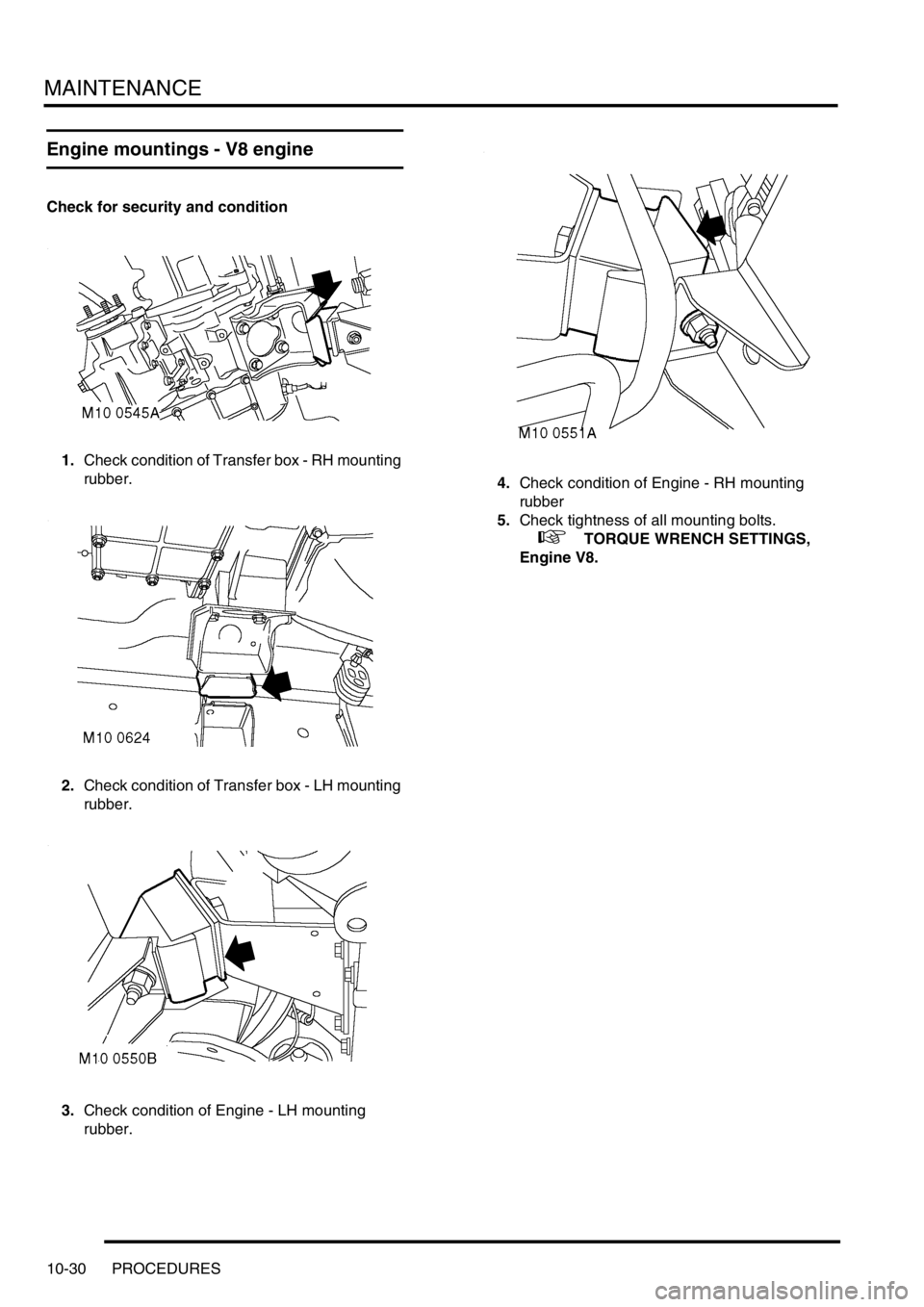
Check for security and condition
1.Check condition of Transfer box - RH mounting
rubber.
2.Check condition of Transfer box - LH mounting
rubber.
3.Check condition of Engine - LH mounting
rubber.4.Check condition of Engine - RH mounting
rubber
5.Check tightness of all mounting bolts.
+ TORQUE WRENCH SETTINGS,
Engine V8.
Page 154 of 1529

MAINTENANCE
PROCEDURES 10-31
Road/roller test
WARNING: Roller test must be restricted to 3
mph (5 km/h). If 2 wheel rolling road is to be used,
disconnect propeller shaft from the transfer box
output shaft driving the axle which is NOT on the
rolling road.
Testing
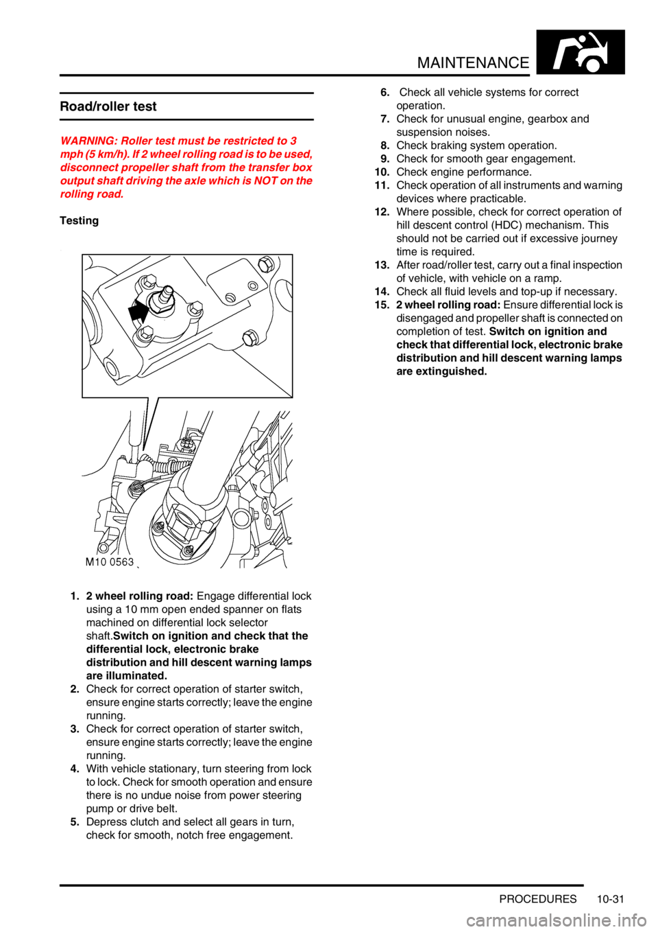
1. 2 wheel rolling road: Engage differential lock
using a 10 mm open ended spanner on flats
machined on differential lock selector
shaft.Switch on ignition and check that the
differential lock, electronic brake
distribution and hill descent warning lamps
are illuminated.
2.Check for correct operation of starter switch,
ensure engine starts correctly; leave the engine
running.
3.Check for correct operation of starter switch,
ensure engine starts correctly; leave the engine
running.
4.With vehicle stationary, turn steering from lock
to lock. Check for smooth operation and ensure
there is no undue noise from power steering
pump or drive belt.
5.Depress clutch and select all gears in turn,
check for smooth, notch free engagement.6. Check all vehicle systems for correct
operation.
7.Check for unusual engine, gearbox and
suspension noises.
8.Check braking system operation.
9.Check for smooth gear engagement.
10.Check engine performance.
11.Check operation of all instruments and warning
devices where practicable.
12.Where possible, check for correct operation of
hill descent control (HDC) mechanism. This
should not be carried out if excessive journey
time is required.
13.After road/roller test, carry out a final inspection
of vehicle, with vehicle on a ramp.
14.Check all fluid levels and top-up if necessary.
15. 2 wheel rolling road: Ensure differential lock is
disengaged and propeller shaft is connected on
completion of test. Switch on ignition and
check that differential lock, electronic brake
distribution and hill descent warning lamps
are extinguished.
Page 155 of 1529
Page 156 of 1529
ENGINE - V8
DESCRIPTION AND OPERATION 12-2-1
ENGIN E - V 8 DESCRIPTION AND OPERAT ION
V8 Engine
Page 157 of 1529
ENGINE - V8
12-2-2 DESCRIPTION AND OPERATION
Cylinder head components
Page 158 of 1529
ENGINE - V8
DESCRIPTION AND OPERATION 12-2-3
1Split pin
2Washers
3Spring
4Rocker arm
5Pedestal bolt
6Pedestal
7Push rod
8Hydraulic tappet
9Rocker shaft
10Cylinder head - left hand
11Gasket - rocker cover
12Rocker cover - left hand
13Bolt - rocker cover
14Valve spring cap
15Valve stem oil seals
16Collets
17Valve spring18Bolt - engine lifting bracket
19Engine lifting bracket
20Valve seat insert
21Exhaust valve
22Clamp - inlet manifold gasket
23Seal - inlet manifold gasket
24Bolt - inlet manifold gasket clamp
25Gasket - inlet manifold
26Inlet valve
27Gasket - cylinder head
28Gasket - exhaust manifold
29Cylinder head - right hand
30Spark plug
31Bolt - cylinder head
32Valve guide
33Rocker cover - right hand
34Engine oil filler cap
Page 159 of 1529
ENGINE - V8
12-2-4 DESCRIPTION AND OPERATION
Cylinder block components
Page 160 of 1529

ENGINE - V8
DESCRIPTION AND OPERATION 12-2-5
1Core plugs
2Cylinder block
3Camshaft
4Dipstick tube, clamp and bolt
5Woodruff key
6Timing chain
7Camshaft timing gear
8Washer
9Bolt - camshaft timing gear
10Thrust plate - camshaft end-float
11Bolt - camshaft thrust plate
12Gasket - timing cover
13Timing cover
14Oil pressure switch
15Bolt
16Crankshaft front oil seal
17Oil filter element
18Crankshaft front pulley
19Washer
20Bolt - crankshaft front pulley
21Upper main bearing shell
22Upper centre main bearing shell and thrust
washer
23Crankshaft
24Woodruff key
25Crankshaft timing gear
26Lower main bearing shells
27Numbers 1, 2 and 3 main bearing caps
28Bolt - main bearing caps
29Oil pick-up pipe and strainer30'O' ring
31Bolt - oil pick-up pipe
32Gasket - sump
33Sump
34Bolt - sump
35Sump oil drain plug
36Sealing washer
37Spacer, washers and nut - oil pick-up pipe
38Number 4 main bearing cap
39Bolt - connecting rod big-end bearing cap
40Connecting rod big-end bearing shell - lower
41Connecting rod big-end bearing cap
42Number 5 - rear main bearing cap
43Cruciform seal - rear main bearing cap
44Number 5 - rear main bearing shell
45Crankshaft rear oil seal
46Crankshaft knock sensor
47Side bolt - main bearing cap
48Side Allen bolt - main bearing cap
49Dowty washers
50Connecting rod big-end bearing shell - upper
51Connecting rod
52Piston
53Gudgeon pin
54Oil control ring
55Top compression ring
562nd compression ring
57Flywheel/drive plate and starter ring gear
58Bolt - flywheel/drive plate
Trending: automatic transmission fluid, light, jacking points, language, battery capacity, ESP inoperative, air bleeding


