LAND ROVER DISCOVERY 1999 Workshop Manual
Manufacturer: LAND ROVER, Model Year: 1999, Model line: DISCOVERY, Model: LAND ROVER DISCOVERY 1999Pages: 1529, PDF Size: 34.8 MB
Page 111 of 1529

TORQUE WRENCH SETTINGS
06-20
Heating and air conditioning
Wipers and washers
TORQUE DESCRIPTION METRIC IMPERIAL
Heater assembly16 Nm (12 lbf.ft)
Compressor bolts22 Nm (16 lbf.ft)
Blower motor19 Nm (14 lbf.ft)
Compressor to mounting bracket bolts 25 Nm (18 lbf.ft)
A/C pipes to compressor bolts 10 Nm (7 lbf.ft)
Condenser pipe bolt 5 Nm (3.7 lbf.ft)
Receiver drier to bracket bolts 5 Nm (3.7 lbf.ft)
Adaptor block to receiver drier bolt 5 Nm (3.7 lbf.ft)
Evaporator pipe bolts 5 Nm (3.7 lbf.ft)
Dual pressure switch to receiver drier 10 Nm (7 lbf.ft)
Air conditioning pipes to receiver drier bolts 5 Nm (3.7 lbf.ft)
TX valve pressure pipe union 22 Nm (16 lbf.ft)
Evaporator pipe to TXV valve 32 Nm (24 lbf.ft)
Evaporator assembly to body bolts 16 Nm (12 lbf.ft)
High and low pressure pipe, bolts 10 Nm (7 lbf.ft)
Fuel burning heater Torx bolts 25 Nm (18 lbf.ft)
TORQUE DESCRIPTION METRIC IMPERIAL
Link to motor spindle 7 Nm (5.2 lbf.ft)
Front motor assembly 2.5 Nm (1.8 lbf.ft)
Spindle nut 3 Nm (2.2 lbf.ft)
Wiper arm nut13 Nm (10 lbf.ft)
Page 112 of 1529

TORQUE WRENCH SETTINGS
06-21
Electrical
TORQUE DESCRIPTION METRIC IMPERIAL
Alternator support stay 25 Nm (18 lbf.ft)
Alternator lead - Td5 6 Nm (4.4 lbf.ft)
Auxiliary drive belt tensioner bolt 50 Nm (37 lbf.ft)
Alternator pulley80 Nm (59 lbf.ft)
Alternator B+ nut - V8 18 Nm (13 lbf.ft)
Alternator B+ nut - V8 5 Nm (3.7 lbf.ft)
Starter motor - Td5 27 Nm (20 lbf.ft)
Starter motor solenoid 10 Nm (7 lbf.ft)
Starter motor - V8 44 Nm (32 lbf.ft)
Alternator45 Nm (33 lbf.ft)
Starter motor heat shield - V8 10 Nm (7 lbf.ft)
Horn13 Nm (10 lbf.ft)
Battery carrier bolts 28 Nm (21 lbf.ft)
Page 113 of 1529

Page 114 of 1529

LIFTING AND TOWING
08-1
LIFTING AND TOWING
LIFTING
The following instructions must be carried out before
raising the vehicle off the ground.
lUse a solid level ground surface.
lApply hand brake.
lSelect 'P' (Automatic gearbox) or 1st gear
(Manual gearbox) in main gearbox.
lSelect Low range in transfer gearbox.
To avoid damage occurring to the under body
components of the vehicle the following jacking
procedures must be adhered to.
DO NOT POSITION JACKS OR AXLE STANDS
UNDER THE FOLLOWING COMPONENTS:
lBody structure
lBumpers
lFuel lines
lBrake lines
lFront radius arms
lPanhard rod
lSteering linkage
lRear trailing arms
lFuel tank
lEngine sump
lGearbox bell housing
Vehicle jack
The jack provided with the vehicle is only intended for
use in an emergency, for changing a tyre. DO NOT
use the jack for any other purpose. Refer to Owner's
Handbook for vehicle jack location points and
procedure. Never work under a vehicle supported
solely by the vehicle jack.
Hydraulic jack
A hydraulic jack with a minimum 1500 kg, 3,300 lbs
load capacity must be used. Do not commence
work on the underside of the vehicle until
suitable axle stands have been positioned under
the axle.
WARNING: Always chock the wheels when
jacking. The hand brake acts on the
transmission, not the rear wheels, and may be
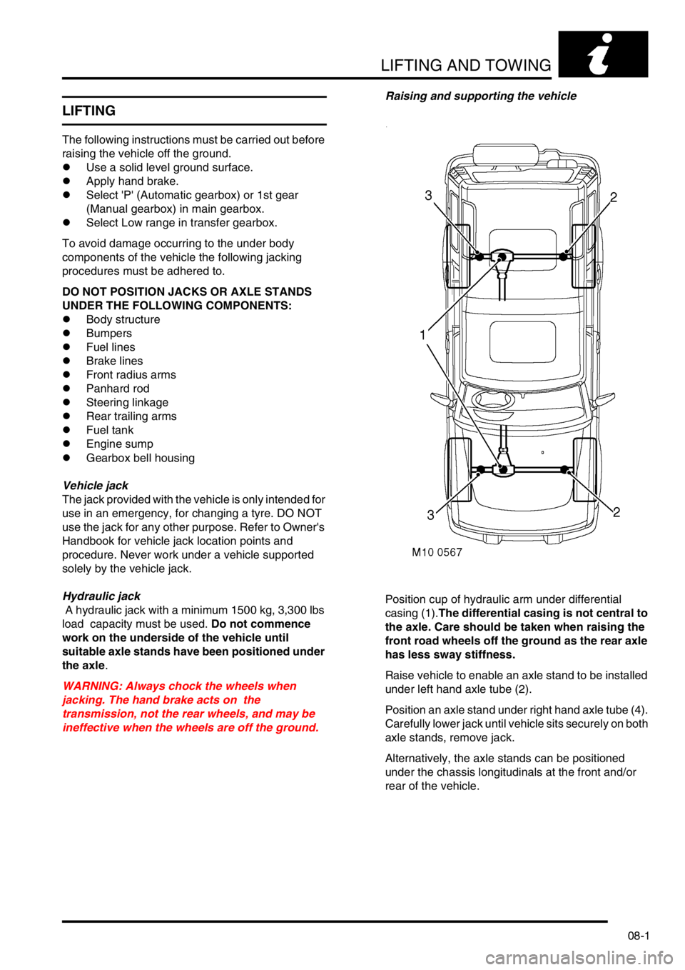
ineffective when the wheels are off the ground.Raising and supporting the vehicle
Position cup of hydraulic arm under differential
casing (1).The differential casing is not central to
the axle. Care should be taken when raising the
front road wheels off the ground as the rear axle
has less sway stiffness.
Raise vehicle to enable an axle stand to be installed
under left hand axle tube (2).
Position an axle stand under right hand axle tube (4).
Carefully lower jack until vehicle sits securely on both
axle stands, remove jack.
Alternatively, the axle stands can be positioned
under the chassis longitudinals at the front and/or
rear of the vehicle.
Page 115 of 1529

LIFTING AND TOWING
08-2
Before commencing work on underside of vehicle re-
check security of vehicle on stands.
WARNING: Always chock the wheels when
jacking. The hand brake acts on the the
transmission, not the rear wheels, and may be
ineffective when the wheels are off the ground.
Reverse procedure when removing vehicle from
stands.
Hydraulic ramps
Use only a 'drive on' type ramp which supports a
vehicle by it's own road wheels. If a 'wheel free'
condition is required, use a 'drive on' ramp
incorporating a 'wheel free' system that supports
under axle casings. Alternatively, place vehicle on a
firm, flat floor and support on axle stands.
TOWING
Towing
The vehicle has permanent four wheel drive. The
following towing instructions must be adhered
to:
Towing on 4 wheels with driver
Turn ignition key to position '1' to release steering
lock.
Select neutral in main gearbox and transfer gearbox.
Secure tow rope, chain or cable to towing eye.
Release the handbrake.
The brake servo and power assisted steering
system will not be functional without the engine
running. Greater pedal pressure will be required
to apply the brakes, the steering system will
require greater effort to turn the front road
wheels. The vehicle tow connection should be
used only in normal road conditions, 'snatch'
recovery should be avoided.
Suspended tow
To prevent vehicle damage, front or rear
propeller shaft MUST BE removed, dependent
upon which axle is being trailed.
Mark propeller shaft drive flanges at transfer box and
axles with identification lines to enable the propeller
shaft to be refitted in its original position.
Page 116 of 1529

LIFTING AND TOWING
08-3
Remove the propeller shaft fixings, remove the shaft
from the vehicle.
If the front axle is to be trailed turn ignition key to
position '1' to release steering lock.
The steering wheel and/or linkage must be
secured in a straight ahead position. DO NOT use
the steering lock mechanism for this purpose.
Towing eyes
The towing eyes at the front and rear of the vehicle
are designed for vehicle recovery purposes only and
must NOT be used to tow a trailer or caravan.
Front:A single towing eye, set behind a removable
panel in the front spoiler. DO NOT use the front
lashing rings for towing.Rear: A pair of towing eyes at the rear of the vehicle
can be used as lashing rings and for towing another
light vehicle.
Page 117 of 1529

LIFTING AND TOWING
08-4
TRANSPORTING
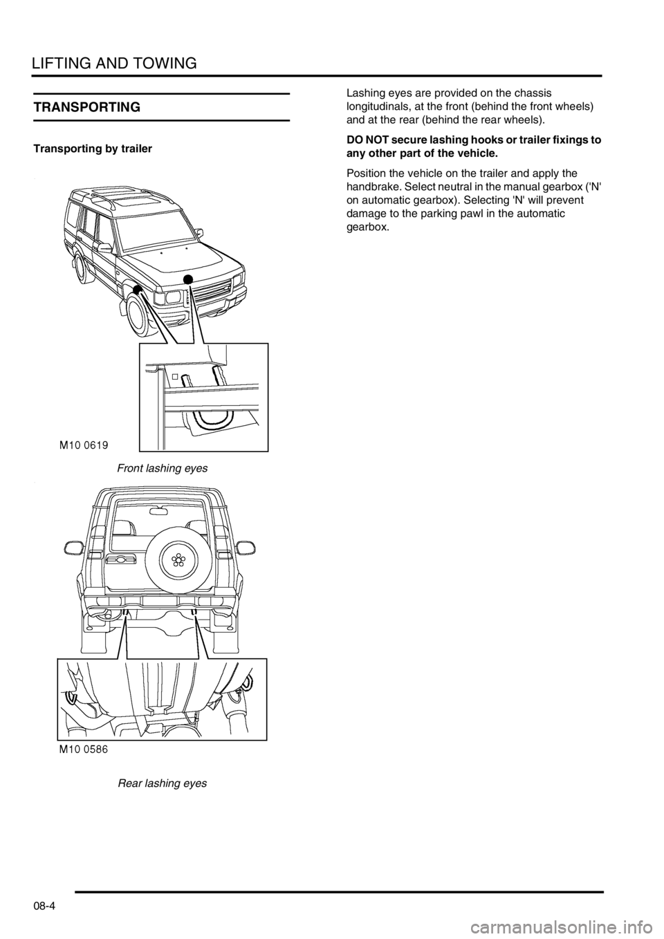
Transporting by trailer
Front lashing eyes
Rear lashing eyesLashing eyes are provided on the chassis
longitudinals, at the front (behind the front wheels)
and at the rear (behind the rear wheels).
DO NOT secure lashing hooks or trailer fixings to
any other part of the vehicle.
Position the vehicle on the trailer and apply the
handbrake. Select neutral in the manual gearbox ('N'
on automatic gearbox). Selecting 'N' will prevent
damage to the parking pawl in the automatic
gearbox.
Page 118 of 1529

CAPACITIES, FLUIDS, LUBRICANTS AND SEALANTS
09-1
CAPACITIES, FLUIDS, LUBRICANTS AND SEALANTS
Capacities
The following capacities are only an approximation of
the amount of fluid required to fill the respective
system.
Capacities - UK EURO ROWCapacities - NAS
Refrigerant - A/C system
Component Metric Units
Fuel tank 95 litres
Engine - Td5:
⇒ Engine oil and filter change 7.2 litres
⇒ Fill from dry 8.2 litres
Engine - V8 with oil cooler:
⇒Engine oil and filter change 6.27 litres
⇒Engine oil refill from dry: 7 litres
Engine - V8 without oil cooler:
⇒Engine oil and filter change 5.8 litres
⇒ Engine oil refill from dry 6.5 litres
Manual gearbox without oil cooler:
⇒ Refill 2.3 litres
⇒ Fill from dry 2.6 litres
Manual gearbox with oil cooler:
⇒ Refill 2.8 litres
⇒ Fill from dry 3.1 litres
Automatic gearbox fill from dry 9.7 litres
Transfer box:
⇒ Refill 2.0 litres
⇒ Fill from dry 2.3 litres
Front and rear axle:
⇒ Refill 1.6 litres
⇒ Fill from dry 1.7 litres
Cooling system - Td5 Engine:
⇒ Refill 8 litres
⇒ Fill from dry 13 litres
Cooling system - V8 Engine:
⇒ Refill 12 litres
⇒ Fill from dry 13 litres
Component US Units
Fuel tank 25.5 gal
Engine - V8 with oil cooler:
⇒ Engine oil and filter change 6.6 qt
⇒ Engine oil refill from dry 7.4 qt
Engine - V8 without oil cooler:
⇒ Engine oil and filter change 6.1 qt
⇒ Engine oil refill from dry 6.9 qt
Automatic gearbox fill from dry
19.7 pt
Transfer box:
⇒ Refill 4.1 pt
⇒ Fill from dry 4.8 pt
Front and rear axle:
⇒ Refill 3.4 pt
⇒ Fill from dry 3.6 pt
Cooling system - V8 Engine:
⇒ Refill 24.2 pt
⇒ Fill from dry 26.2 pt
⇒Front A/C 700 ± 25 g
⇒Front/rear A/C 900 ± 25 g
Page 119 of 1529

CAPACITIES, FLUIDS, LUBRICANTS AND SEALANTS
09-2
Fluids
Anti-freeze
Use Havoline Extended Life Coolant (XLC), or any
ethylene glycol based anti-freeze (containing no
methanol) with only Organic Acid Technology (OAT)
corrosion inhibitors, to protect the cooling system
CAUTION: No other anti-freeze should be used
with Havoline Extended Life Coolant.
The cooling system should be drained, flushed and
refilled with the correct amount of anti-freeze solution
at the intervals given on the Service Maintenance
Check Sheet.
After filling with anti-freeze solution, attach a warning
label to a prominent position on the vehicle stating
the type of anti-freeze contained in the cooling
system to ensure that the correct type is used for
topping-up.
Brake/Clutch fluid
Use only DOT 4 brake fluid.
PAS fluid
Use Texaco cold climate power assisted steering
fluid PSF 14315.
ACE fluid
Where ambient temperature falls below -20° C (-4°
F), use only Texaco cold climate power assisted
steering fluid PSF 14315. Where ambient
temperature remains above -20° C (-4° F), use either
Texaco cold climate power assisted steering fluid ,
Dexron 11 or Dexron 111 non-synthetic fluid.
Air conditioning
Use only refrigerant R134a.
Refrigerant oil
Use only Nippon Denso ND-oil 8.
Refrigerant oil absorbs water and must not be stored
for long periods. Do not pour unused oil back into the
container.
NOTE: The total quantity of refrigerant oil in the
system is 180 ml.
CAUTION: Do not use any other type of
refrigerant oil.
Anti-Freeze Concentration
The overall anti-freeze concentration should not fall,
by volume, below 50% to ensure that the anti-
corrosion properties of the coolant are maintained.
Anti-freeze concentrations greater than 60% are not
recommended as cooling efficiency will be impaired.
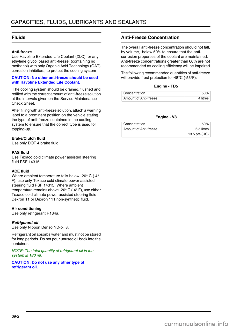
The following recommended quantities of anti-freeze
will provide frost protection to -48°C (-53°F):
Engine - TD5
Engine - V8
Concentration 50%
Amount of Anti-freeze 4 litres
Concentration 50%
Amount of Anti-freeze 6.5 litres
13.5 pts (US)
Page 120 of 1529

CAPACITIES, FLUIDS, LUBRICANTS AND SEALANTS
09-3
Lubrication
General
The engine and other lubricating systems are filled
with high-performance lubricants giving prolonged
life.
CAUTION: Always use a high quality oil of the
correct viscosity range in the engine. The use of
oil of the incorrect specification can lead to high
oil and fuel consumption and ultimately to
damaged components.
Oil to the correct specification contains additives
which disperse the corrosive acids formed by
combustion and prevent the formation of sludge
which can block the oil ways. Additional oil additives
should not be used.
Always adhere to the recommended servicing
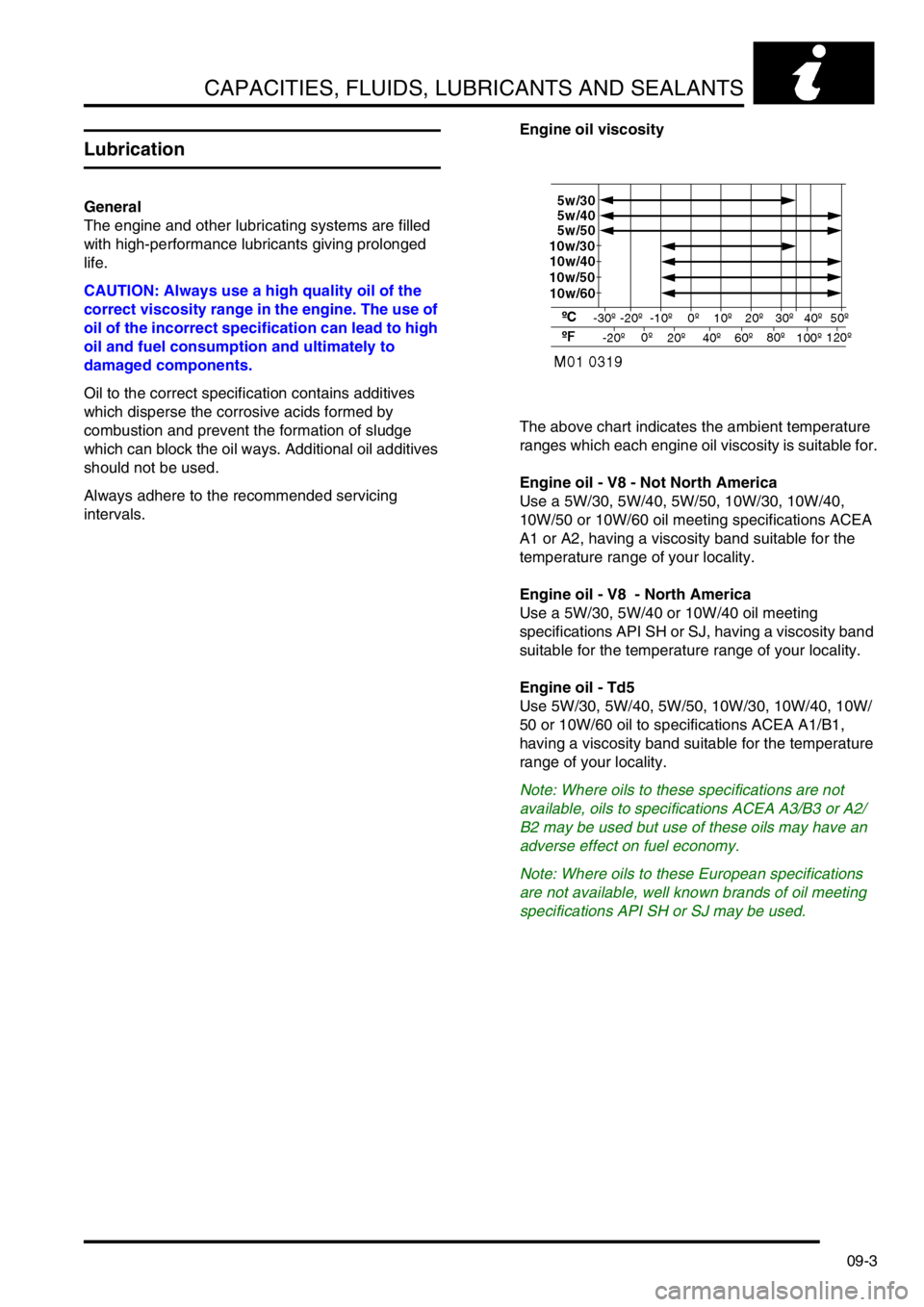
intervals.Engine oil viscosity
The above chart indicates the ambient temperature
ranges which each engine oil viscosity is suitable for.
Engine oil - V8 - Not North America
Use a 5W/30, 5W/40, 5W/50, 10W/30, 10W/40,
10W/50 or 10W/60 oil meeting specifications ACEA
A1 or A2, having a viscosity band suitable for the
temperature range of your locality.
Engine oil - V8 - North America
Use a 5W/30, 5W/40 or 10W/40 oil meeting
specifications API SH or SJ, having a viscosity band
suitable for the temperature range of your locality.
Engine oil - Td5
Use 5W/30, 5W/40, 5W/50, 10W/30, 10W/40, 10W/
50 or 10W/60 oil to specifications ACEA A1/B1,
having a viscosity band suitable for the temperature
range of your locality.
Note: Where oils to these specifications are not
available, oils to specifications ACEA A3/B3 or A2/
B2 may be used but use of these oils may have an
adverse effect on fuel economy.
Note: Where oils to these European specifications
are not available, well known brands of oil meeting
specifications API SH or SJ may be used.