LAND ROVER DISCOVERY 1999 Workshop Manual
Manufacturer: LAND ROVER, Model Year: 1999, Model line: DISCOVERY, Model: LAND ROVER DISCOVERY 1999Pages: 1529, PDF Size: 34.8 MB
Page 121 of 1529

CAPACITIES, FLUIDS, LUBRICANTS AND SEALANTS
09-4
Gearbox oil
Manual Gearbox: Use Texaco MTF 94 oil for refill
and topping-up.
Automatic Gearbox: Use Texamatic 9226, ATF
Dexron 11D or Dexron 111 for refill and topping-up
Transfer box
Use Texaco Multi-Gear 75W/90R or oil meeting
specification API GL5.
Front and rear axles
Use Texaco Multi-Gear 75W/90R.
Air Conditioning
Use lubricating oil Nippon Denso ND-8.
General Greasing
Use Multipurpose Lithium Base Grease N.L.G.I.
consistency No. 2.
Bonnet latch
Lubricate cable and latch with oil.
Sealants
The following table lists those sealants which are
used during repair / overhaul procedures covered in
this manual; it is essential that the sealant specified
for a particular procedure is used at all times.
Component Application Land Rover
Part No.
Td5 Engine Timing chain fixed
guide Allen screwSTC 50552
Td5 Engine Camshaft cover
gasket joint lineSTC 50550
Td5 Engine Oil pick-up strainer
Torx screwsSTC 50552
Td5 Engine Oil pump drive
sprocket retaining
boltSTC 50552
Td5 Engine Timing chain cover,
crankshaft rear oil
seal and sump
gasket joint linesSTC 50550
Td5 Engine Oil pressure relief
valve plugSTC 50552
Td5 Engine Camshaft carrier to
cylinder headSTC 4600
Td5 Engine Timing cover STC 50550
V8 Engine Sump gasket to
cylinder blockSTC 50550
V8 Engine 'V' grooves at end
of cylinder head -
Inlet manifold
gasketSTC 50550
V8 Engine Cruciform seal
endsSTC 50550
V8 Engine Dipstick tube STC 50554
V8 Engine Timing cover bolts STC 50552
Engine
Management
System - V8Engine coolant
temperature (ECT)
sensor threadsSTC 50552
Manifolds and
Exhaust
System - V8'V' grooves at end
of cylinder head -
Inlet manifold
gasketSTC 50550
Manual
Gearbox -
R380Gear selector
housingSTC 4404
Manual
Gearbox -
R380Selector housing
boltsSTC 50552
Manual
Gearbox -
R380Input shaft oil seal
housingSTC 4404
Manual
Gearbox -
R380Reverse inhibitor
shaft threadsSTC 50552
Page 122 of 1529

CAPACITIES, FLUIDS, LUBRICANTS AND SEALANTS
09-5
Manual
Gearbox -
R380Gate plate bolts STC 50552
Manual
Gearbox -
R380Gear case to
extension housingSTC 4404
Manual
Gearbox -
R380Extension housing
boltsSTC 50552
Manual
Gearbox -
R380Gear change lever
yoke Allen screwSTC 50552
Manual
Gearbox -
R380Gear case to centre
plateSTC 4404
Manual
Gearbox -
R380Detent plugs STC 50552
Manual
Gearbox -
R380Bias spring
adjustment plate
boltsSTC 50552
Transfer Box -
LT230SEBottom cover plate STC 4600
Transfer Box -
LT230SEBottom cover plate
boltsSTC 50552
Transfer Box -
LT230SEFront output
housing core plugSTC 3811
Transfer Box -
LT230SETransfer box to
gear case bolts -
Petrol and Diesel
enginesSTC 50552
Transfer Box -
LT230SETransfer box to
gear case studs -
Petrol and Diesel
enginesSTC 50552
Transfer Box -
LT230SERear cover STC 4600
Transfer Box -
LT230SEDifferential warning
lamp switch(es)STC 50552
Transfer Box -
LT230SEHigh/Low selector
warning lamp
switchSTC 50552
Transfer Box -
LT230SERear output shaft
housingSTC 4600
Transfer Box -
LT230SERear output shaft
housing boltsSTC 50552
Transfer Box -
LT230SEHigh/Low selector
fork set screwSTC 50552
Transfer Box -
LT230SEInterlock solenoid
selector cover - Up
to 03 MYSTC 4600
Transfer Box -
LT230SEInterlock solenoid
circlip - 03 MY
onwardsSTC 50551
Transfer Box -
LT230SENeutral sensor STC 50552
Transfer Box -
LT230SEIntermediate shaft
retaining plate boltSTC 50552Transfer Box -
LT230SESide cover STC 4600
Transfer Box -
LT230SESide cover bolts STC 50552
Transfer Box -
LT230SEDifferential lock
selector shaft
detent plugSTC 50552
Transfer Box -
LT230SEDifferential lock
selector housing
boltsSTC 50552
Transfer Box -
LT230SEFront output shaft
housingSTC 4600
Transfer Box -
LT230SEFront output shaft
housing boltsSTC 50552
Transfer Box -
LT230SEHigh/Low selector
shaft detent plugSTC 50552
Transfer Box -
LT230SEInput gear bearing
housingSTC 4600
Transfer Box -
LT230SERear cover stud nut
and boltSTC 50552
Transfer Box -
LT230SEHigh/Low cross
shaft housingSTC 4600
Transfer Box -
LT230SEHigh/Low cross
shaft housing boltsSTC 50552
Automatic
gearbox -
ZFHP22-24Torque converter
housing to engine
boltsSTC 50553
Rear Axle and
Final DriveDifferential cover to
casingSTC 3811
Rear Axle and
Final DriveDifferential cover to
casing boltsSTC 50552
Front axle Differential cover to
casingSTC 3811
Front axle Differential cover to
casing boltsSTC 50552
Front
suspensionDrive shaft to hub STC 50554
Rear
suspensionDrive shaft to hub STC 50554
Rear
suspensionSLS air compressor
boltsSTC 50552
Page 123 of 1529

Page 124 of 1529
MAINTENANCE
PROCEDURES 10-1
MAINTENANCE PROCEDURES
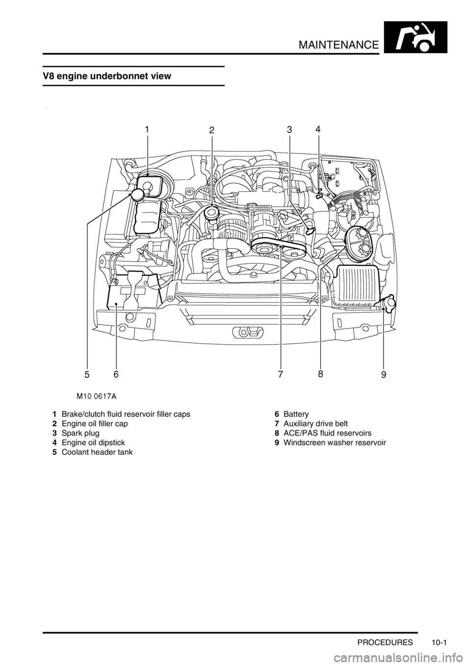
V8 engine underbonnet view
1Brake/clutch fluid reservoir filler caps
2Engine oil filler cap
3Spark plug
4Engine oil dipstick
5Coolant header tank6Battery
7Auxiliary drive belt
8ACE/PAS fluid reservoirs
9Windscreen washer reservoir
Page 125 of 1529
MAINTENANCE
10-2 PROCEDURES
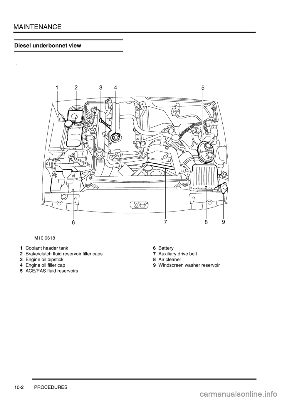
Diesel underbonnet view
1Coolant header tank
2Brake/clutch fluid reservoir filler caps
3Engine oil dipstick
4Engine oil filler cap
5ACE/PAS fluid reservoirs6Battery
7Auxiliary drive belt
8Air cleaner
9Windscreen washer reservoir
Page 126 of 1529
MAINTENANCE
PROCEDURES 10-3
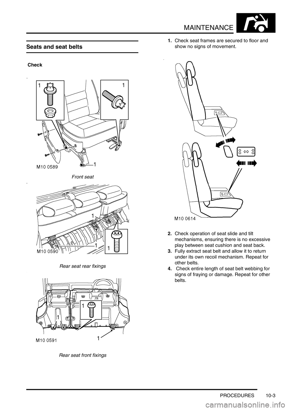
Seats and seat belts
Check
Front seat
Rear seat rear fixings
Rear seat front fixings1.Check seat frames are secured to floor and
show no signs of movement.
2.Check operation of seat slide and tilt
mechanisms, ensuring there is no excessive
play between seat cushion and seat back.
3.Fully extract seat belt and allow it to return
under its own recoil mechanism. Repeat for
other belts.
4. Check entire length of seat belt webbing for
signs of fraying or damage. Repeat for other
belts.
Page 127 of 1529
MAINTENANCE
10-4 PROCEDURES
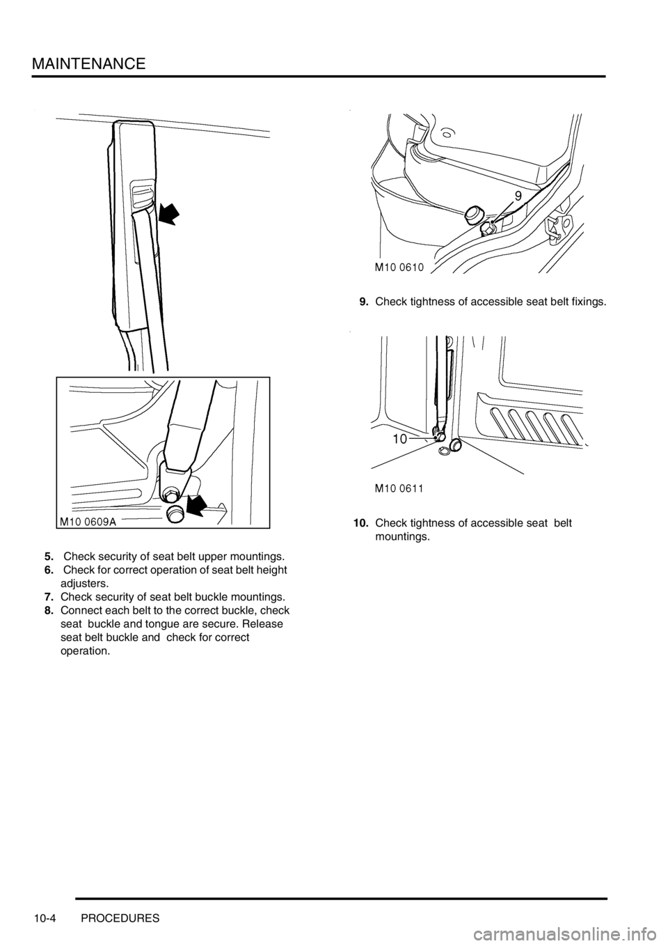
5. Check security of seat belt upper mountings.
6. Check for correct operation of seat belt height
adjusters.
7.Check security of seat belt buckle mountings.
8.Connect each belt to the correct buckle, check
seat buckle and tongue are secure. Release
seat belt buckle and check for correct
operation.9.Check tightness of accessible seat belt fixings.
10.Check tightness of accessible seat belt
mountings.
Page 128 of 1529
MAINTENANCE
PROCEDURES 10-5
Lamps, horns and warning indicators
Check
1.Switch on side, head and tail lamps and check
operation.
2.Check headlamp levelling operation.
3.Check turn signals and hazard warning lamps
for correct operation.
4.Press brake pedal and check operation of
brake lamps.
5.Check all exterior lamp lenses for clarity and
condition. Pay particular attention to headlamp
lenses for signs of stone chips or damage.
6.Check horn for loud, clear sound.
7.Switch on headlamps (with ignition switch at 'O'
position) and check light reminder warning
operates when door is opened.
8.Check operation of interior courtesy lights.
9.Check operation of all instrument pack warning
and indicator lights.
Wipers and washers
Check
1. Operate screen washer and switch on wipers.
Ensure washer jets are correctly aimed and
check for smooth, smear free operation of
wiper blades across screen at all speeds
including intermittent.
2.Repeat operation for rear screen washers/
wipers.
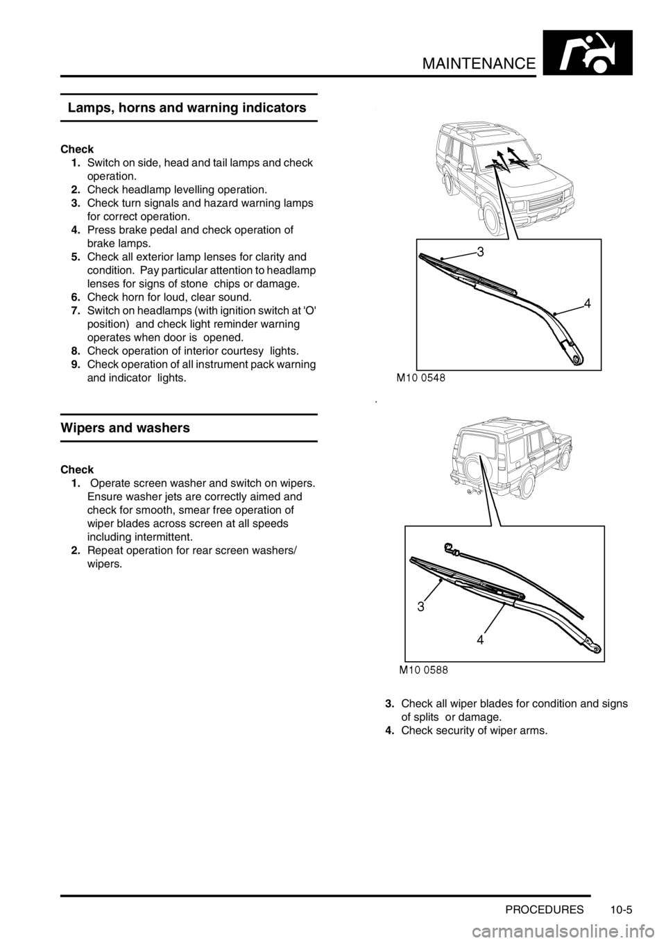
3.Check all wiper blades for condition and signs
of splits or damage.
4.Check security of wiper arms.
Page 129 of 1529
MAINTENANCE
10-6 PROCEDURES
Handbrake
Check
1.With the vehicle stationary, on a level surface,
apply and release handbrake and check for
correct operation.
+ BRAKES, ADJUSTMENTS,
Handbrake.
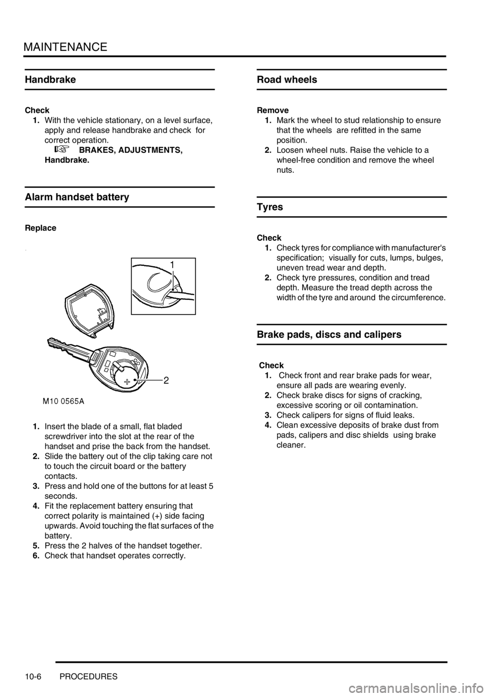
Alarm handset battery
Replace
1.Insert the blade of a small, flat bladed
screwdriver into the slot at the rear of the
handset and prise the back from the handset.
2.Slide the battery out of the clip taking care not
to touch the circuit board or the battery
contacts.
3.Press and hold one of the buttons for at least 5
seconds.
4.Fit the replacement battery ensuring that
correct polarity is maintained (+) side facing
upwards. Avoid touching the flat surfaces of the
battery.
5.Press the 2 halves of the handset together.
6.Check that handset operates correctly.
Road wheels
Remove
1.Mark the wheel to stud relationship to ensure
that the wheels are refitted in the same
position.
2.Loosen wheel nuts. Raise the vehicle to a
wheel-free condition and remove the wheel
nuts.
Tyres
Check
1.Check tyres for compliance with manufacturer's
specification; visually for cuts, lumps, bulges,
uneven tread wear and depth.
2.Check tyre pressures, condition and tread
depth. Measure the tread depth across the
width of the tyre and around the circumference.
Brake pads, discs and calipers
Check
1. Check front and rear brake pads for wear,
ensure all pads are wearing evenly.
2.Check brake discs for signs of cracking,
excessive scoring or oil contamination.
3.Check calipers for signs of fluid leaks.
4.Clean excessive deposits of brake dust from
pads, calipers and disc shields using brake
cleaner.
Page 130 of 1529
MAINTENANCE
PROCEDURES 10-7
Road wheel speed sensors
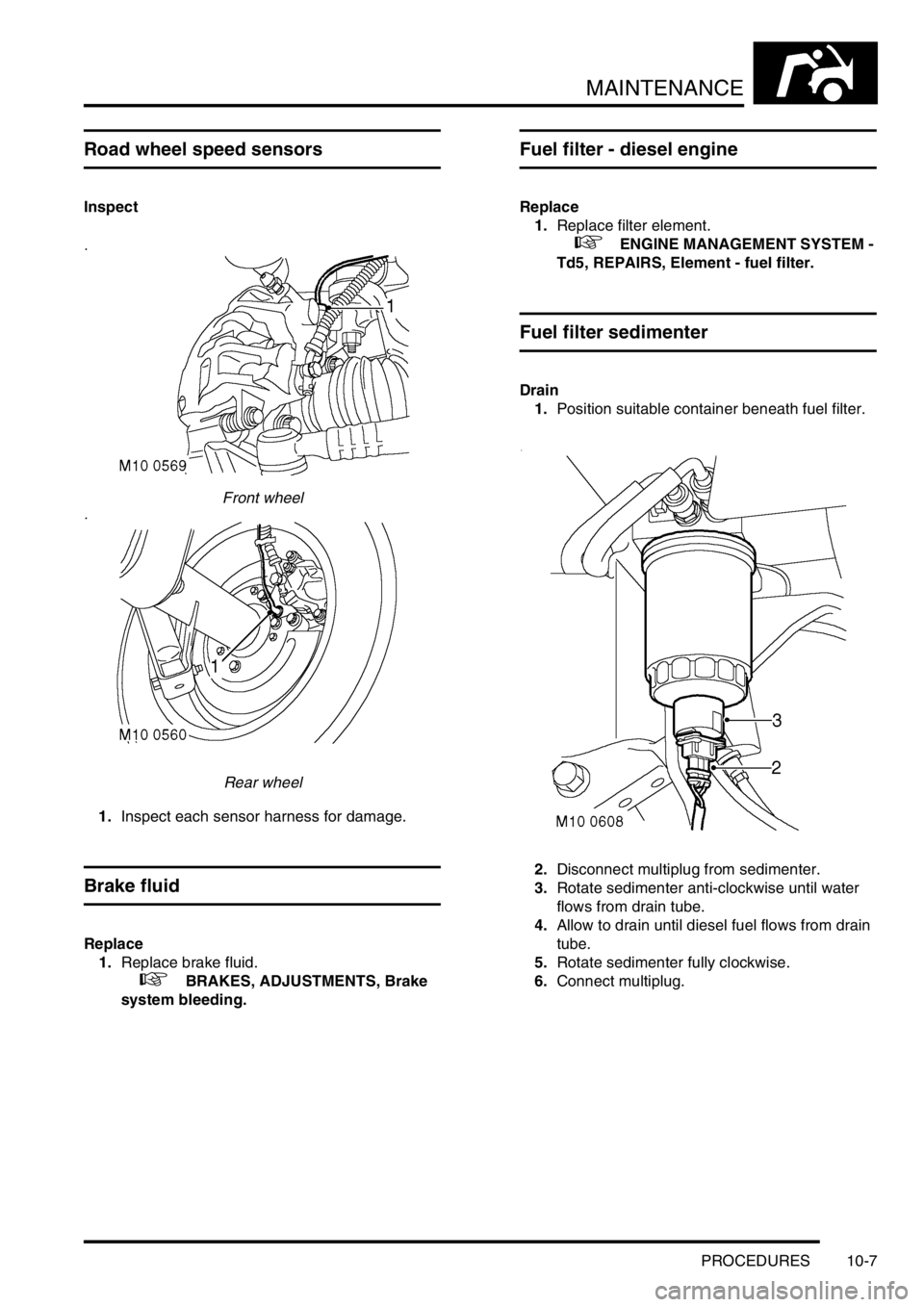
Inspect
Front wheel
Rear wheel
1.Inspect each sensor harness for damage.
Brake fluid
Replace
1.Replace brake fluid.
+ BRAKES, ADJUSTMENTS, Brake
system bleeding.
Fuel filter - diesel engine
Replace
1.Replace filter element.
+ ENGINE MANAGEMENT SYSTEM -
Td5, REPAIRS, Element - fuel filter.
Fuel filter sedimenter
Drain
1.Position suitable container beneath fuel filter.
2.Disconnect multiplug from sedimenter.
3.Rotate sedimenter anti-clockwise until water
flows from drain tube.
4.Allow to drain until diesel fuel flows from drain
tube.
5.Rotate sedimenter fully clockwise.
6.Connect multiplug.