fuse box LAND ROVER DISCOVERY 1999 User Guide
[x] Cancel search | Manufacturer: LAND ROVER, Model Year: 1999, Model line: DISCOVERY, Model: LAND ROVER DISCOVERY 1999Pages: 1529, PDF Size: 34.8 MB
Page 262 of 1529
EMISSION CONTROL - V8
DESCRIPTION AND OPERATION 17-2-29
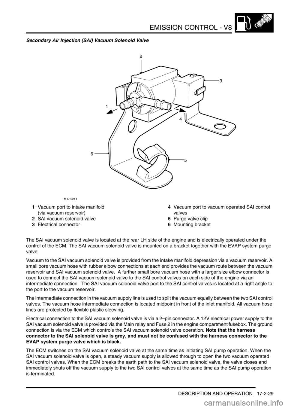
Secondary Air Injection (SAI) Vacuum Solenoid Valve
1Vacuum port to intake manifold
(via vacuum reservoir)
2SAI vacuum solenoid valve
3Electrical connector4Vacuum port to vacuum operated SAI control
valves
5Purge valve clip
6Mounting bracket
The SAI vacuum solenoid valve is located at the rear LH side of the engine and is electrically operated under the
control of the ECM. The SAI vacuum solenoid valve is mounted on a bracket together with the EVAP system purge
valve.
Vacuum to the SAI vacuum solenoid valve is provided from the intake manifold depression via a vacuum reservoir. A
small bore vacuum hose with rubber elbow connections at each end provides the vacuum route between the vacuum
reservoir and SAI vacuum solenoid valve. A further small bore vacuum hose with a larger size elbow connector is
used to connect the SAI vacuum solenoid valve to the SAI control valves on each side of the engine via an
intermediate connection. The SAI vacuum solenoid valve port to the SAI control valves is located at a right angle to
the port to the vacuum reservoir.
The intermediate connection in the vacuum supply line is used to split the vacuum equally between the two SAI control
valves. The vacuum hose intermediate connection is located midpoint in front of the inlet manifold. All vacuum hose
lines are protected by flexible plastic sleeving.
Electrical connection to the SAI vacuum solenoid valve is via a 2–pin connector. A 12V electrical power supply to the
SAI vacuum solenoid valve is provided via the Main relay and Fuse 2 in the engine compartment fusebox. The ground
connection is via the ECM which controls the SAI vacuum solenoid valve operation. Note that the harness
connector to the SAI solenoid valve is grey, and must not be confused with the harness connector to the
EVAP system purge valve which is black.
The ECM switches on the SAI vacuum solenoid valve at the same time as initiating SAI pump operation. When the
SAI vacuum solenoid valve is open, a steady vacuum supply is allowed through to open the two vacuum operated
SAI control valves. When the ECM breaks the earth path to the SAI vacuum solenoid valve, the valve closes and
immediately shuts off the vacuum supply to the two SAI control valves at the same time as the SAI pump operation
is terminated.
M17 0211
1
4
2
3
5
6
Page 276 of 1529

EMISSION CONTROL - V8
DESCRIPTION AND OPERATION 17-2-43
Secondary Air Injection System
Operation
When the engine is started, the engine control module checks the engine coolant temperature and if it is below 55°
C, the ECM grounds the electrical connection to the coil of the secondary air injection (SAI) pump relay.
A 12V battery supply is fed to the inertia switch via fuse 13 in the engine compartment fusebox. When the inertia
switch contacts are closed, the feed passes through the switch and is connected to the coil of the Main relay. An earth
connection from the Main relay coil is connected to the ECM. When the ECM completes the earth path, the coil
energises and closes the contacts of the Main relay.
The Main and Secondary Air Injection (SAI) pump relays are located in the engine compartment fusebox. When the
contacts of the Main relay are closed, a 12V battery supply is fed to the coil of the SAI pump relay. An earth connection
from the coil of the SAI pump relay is connected to the ECM. When the ECM completes the earth path, the coil
energises and closes the contacts of the SAI pump relay to supply 12V to the SAI pump via fusible link 2 in the engine
compartment fusebox. The SAI pump starts to operate, and will continue to do so until the ECM switches off the earth
connection to the coil of the SAI pump relay.
The SAI pump remains operational for a period determined by the ECM and depends on the starting temperature of
the engine, or for a maximum operation period determined by the ECM if the target engine coolant temperature has
not been reached in the usual time.
When the contacts of the main relay are closed, a 12V battery supply is fed to the SAI solenoid valve via Fuse 2 in
the engine compartment fusebox.
The ECM grounds the electrical connection to the SAI vacuum solenoid valve at the same time as it switches on the
SAI pump motor. When the SAI vacuum solenoid valve is energised, a vacuum is provided to the operation control
ports on both of the vacuum operated SAI control valves at the exhaust manifolds. The control vacuum is sourced
from the intake manifold depression and routed to the SAI control valves via a vacuum reservoir and the SAI vacuum
solenoid valve.
The vacuum reservoir is included in the vacuum supply circuit to prevent vacuum fluctuations caused by changes in
the intake manifold depression affecting the operation of the SAI control valves.
When a vacuum is applied to the control ports of the SAI control valves, the valves open to allow pressurised air from
the SAI pump to pass through to the exhaust ports in the cylinder heads for combustion.
When the ECM has determined that the SAI pump has operated for the desired duration, it switches off the earth paths
to the SAI pump relay and the SAI vacuum solenoid valve. With the SAI vacuum solenoid valve de-energised, the
valve closes, cutting off the vacuum supply to the SAI control valves. The SAI control valves close immediately and
completely to prevent any further pressurised air from the SAI pump entering the exhaust manifolds.
The engine coolant temperature sensor incurs a time lag in respect of detecting a change in temperature and the SAI
pump automatically enters a 'soak period' between operations to prevent the SAI pump overheating. The ECM also
compares the switch off and start up temperatures, to determine whether it is necessary to operate the SAI pump.
This prevents the pump running repeatedly and overheating on repeat starts.
Other factors which may prevent or stop SAI pump operation include the prevailing engine speed / load conditions.
Page 316 of 1529

ENGINE MANAGEMENT SYSTEM - V8
DESCRIPTION AND OPERATION 18-2-17
Camshaft Position (CMP) sensor (C0176)
The CMP sensor is located on the front of the engine, above and behind the crankshaft pulley. The CMP sensor is a
Hall effect sensor producing four pulses for every two crankshaft revolutions. The sensor is positioned close to the
camshaft gear wheel, the gear wheel has four slots machined at 90° intervals. This allows the ECM to recognise 4
individual cylinders every camshaft revolution or all 8 cylinders every crankshaft revolution.
The CMP sensor Hall effect works as a magnetic switch. It switches battery voltage on or off depending on the position
of the camshaft gear wheel in relationship to the sensor.
The ECM uses this signal for cylinder recognition to control sequential fuel injection, engine knock and diagnostic
purposes.
Input/Output
Electrical input to the camshaft position sensor is from fuse 2 located in engine compartment fuse box. One output is
sensor earth, the other is the signal output to the ECM via pin 20 of connector C0636.
The CMP sensor can fail the following ways or supply incorrect signal:
lSensor open circuit.
lShort circuit to vehicle battery supply.
lShort circuit to vehicle earth.
lIncorrect fitting of the sensor.
lExcessive camshaft gear wheel tolerance.
lExcessive camshaft endfloat.
lCamshaft and crankshaft misalignment.
lSpeed signal correlation with CKP sensor signal.
lCam wheel magnetised / residual magnetism
In the event of a CMP sensor signal failure any of the following symptoms may be observed:
lIgnition timing reverts to default values from ECM memory.
lLoss of cylinder correction.
lLoss of active knock control.
lLoss of active knock control diagnostics.
lLoss of cylinder identification for misfire diagnostics.
lLoss of quick synchronisation of crankshaft and camshaft for cranking/ start up.
lFuel injection could be 360° out of phase.
lFront HO
2S sensor ageing period diagnostic disabled (NAS only)
Should a malfunction of the component occur the following fault code may be evident and can be retrieved by
TestBook:
The fault condition has to be detected for more than 100 cam pulses (25 revolutions) when the engine speed is greater
than 500 rev/min.
P code J2012 description Land Rover description
P0340 Camshaft position sensor circuit malfunction Open/short circuit to vehicle supply or earth
Page 322 of 1529
ENGINE MANAGEMENT SYSTEM - V8
DESCRIPTION AND OPERATION 18-2-23
Should a malfunction occur, the following fault codes may be evident and can be retrieved by TestBook:
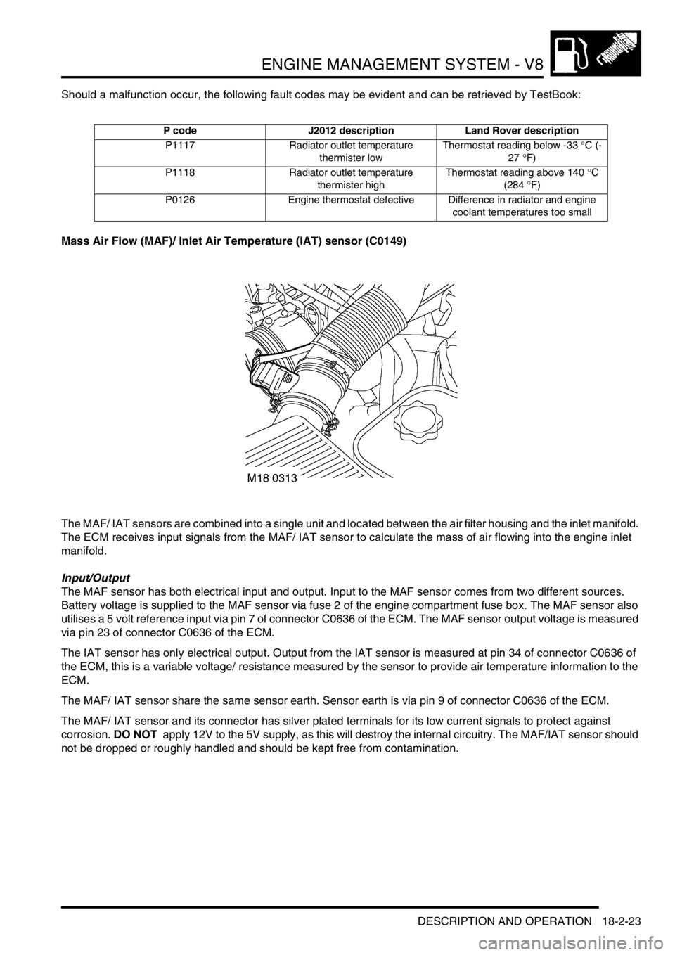
Mass Air Flow (MAF)/ Inlet Air Temperature (IAT) sensor (C0149)
The MAF/ IAT sensors are combined into a single unit and located between the air filter housing and the inlet manifold.
The ECM receives input signals from the MAF/ IAT sensor to calculate the mass of air flowing into the engine inlet
manifold.
Input/Output
The MAF sensor has both electrical input and output. Input to the MAF sensor comes from two different sources.
Battery voltage is supplied to the MAF sensor via fuse 2 of the engine compartment fuse box. The MAF sensor also
utilises a 5 volt reference input via pin 7 of connector C0636 of the ECM. The MAF sensor output voltage is measured
via pin 23 of connector C0636 of the ECM.
The IAT sensor has only electrical output. Output from the IAT sensor is measured at pin 34 of connector C0636 of
the ECM, this is a variable voltage/ resistance measured by the sensor to provide air temperature information to the
ECM.
The MAF/ IAT sensor share the same sensor earth. Sensor earth is via pin 9 of connector C0636 of the ECM.
The MAF/ IAT sensor and its connector has silver plated terminals for its low current signals to protect against
corrosion. DO NOT apply 12V to the 5V supply, as this will destroy the internal circuitry. The MAF/IAT sensor should
not be dropped or roughly handled and should be kept free from contamination.
P code J2012 description Land Rover description
P1117 Radiator outlet temperature
thermister lowThermostat reading below -33 °C (-
27 °F)
P1118 Radiator outlet temperature
thermister highThermostat reading above 140 °C
(284 °F)
P0126 Engine thermostat defective Difference in radiator and engine
coolant temperatures too small
Page 329 of 1529
ENGINE MANAGEMENT SYSTEM - V8
18-2-30 DESCRIPTION AND OPERATION
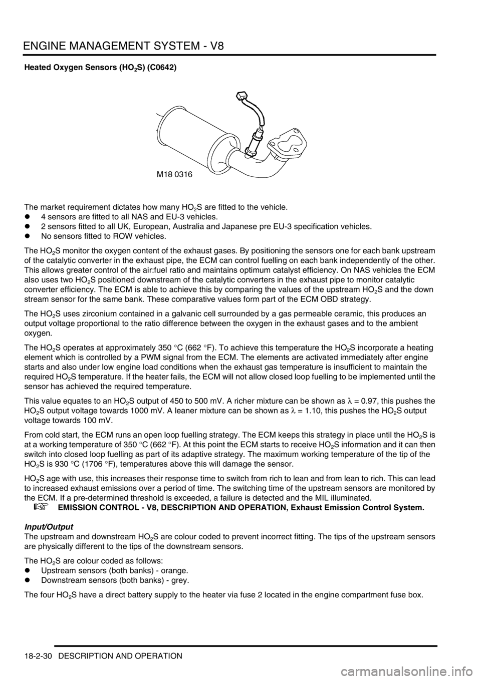
Heated Oxygen Sensors (HO2S) (C0642)
The market requirement dictates how many HO
2S are fitted to the vehicle.
l4 sensors are fitted to all NAS and EU-3 vehicles.
l2 sensors fitted to all UK, European, Australia and Japanese pre EU-3 specification vehicles.
lNo sensors fitted to ROW vehicles.
The HO
2S monitor the oxygen content of the exhaust gases. By positioning the sensors one for each bank upstream
of the catalytic converter in the exhaust pipe, the ECM can control fuelling on each bank independently of the other.
This allows greater control of the air:fuel ratio and maintains optimum catalyst efficiency. On NAS vehicles the ECM
also uses two HO
2S positioned downstream of the catalytic converters in the exhaust pipe to monitor catalytic
converter efficiency. The ECM is able to achieve this by comparing the values of the upstream HO
2S and the down
stream sensor for the same bank. These comparative values form part of the ECM OBD strategy.
The HO
2S uses zirconium contained in a galvanic cell surrounded by a gas permeable ceramic, this produces an
output voltage proportional to the ratio difference between the oxygen in the exhaust gases and to the ambient
oxygen.
The HO
2S operates at approximately 350 °C (662 °F). To achieve this temperature the HO2S incorporate a heating
element which is controlled by a PWM signal from the ECM. The elements are activated immediately after engine
starts and also under low engine load conditions when the exhaust gas temperature is insufficient to maintain the
required HO
2S temperature. If the heater fails, the ECM will not allow closed loop fuelling to be implemented until the
sensor has achieved the required temperature.
This value equates to an HO
2S output of 450 to 500 mV. A richer mixture can be shown as λ = 0.97, this pushes the
HO
2S output voltage towards 1000 mV. A leaner mixture can be shown as λ = 1.10, this pushes the HO2S output
voltage towards 100 mV.
From cold start, the ECM runs an open loop fuelling strategy. The ECM keeps this strategy in place until the HO
2S is
at a working temperature of 350 °C (662 °F). At this point the ECM starts to receive HO
2S information and it can then
switch into closed loop fuelling as part of its adaptive strategy. The maximum working temperature of the tip of the
HO
2S is 930 °C (1706 °F), temperatures above this will damage the sensor.
HO
2S age with use, this increases their response time to switch from rich to lean and from lean to rich. This can lead
to increased exhaust emissions over a period of time. The switching time of the upstream sensors are monitored by
the ECM. If a pre-determined threshold is exceeded, a failure is detected and the MIL illuminated.
+ EMISSION CONTROL - V8, DESCRIPTION AND OPERATION, Exhaust Emission Control System.
Input/Output
The upstream and downstream HO
2S are colour coded to prevent incorrect fitting. The tips of the upstream sensors
are physically different to the tips of the downstream sensors.
The HO
2S are colour coded as follows:
lUpstream sensors (both banks) - orange.
lDownstream sensors (both banks) - grey.
The four HO
2S have a direct battery supply to the heater via fuse 2 located in the engine compartment fuse box.
Page 332 of 1529
ENGINE MANAGEMENT SYSTEM - V8
DESCRIPTION AND OPERATION 18-2-33
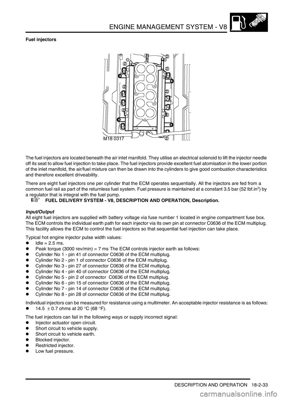
Fuel injectors
The fuel injectors are located beneath the air inlet manifold. They utilise an electrical solenoid to lift the injector needle
off its seat to allow fuel injection to take place. The fuel injectors provide excellent fuel atomisation in the lower portion
of the inlet manifold, the air/fuel mixture can then be drawn into the cylinders to give good combustion characteristics
and therefore excellent driveability.
There are eight fuel injectors one per cylinder that the ECM operates sequentially. All the injectors are fed from a
common fuel rail as part of the returnless fuel system. Fuel pressure is maintained at a constant 3.5 bar (52 lbf.in
2) by
a regulator that is integral with the fuel pump.
+ FUEL DELIVERY SYSTEM - V8, DESCRIPTION AND OPERATION, Description.
Input/Output
All eight fuel injectors are supplied with battery voltage via fuse number 1 located in engine compartment fuse box.
The ECM controls the individual earth path for each injector via its own pin at connector C0636 of the ECM multiplug.
This facility allows the ECM to control the fuel injectors so that sequential fuel injection can take place.
Typical hot engine injector pulse width values:
lIdle = 2.5 ms.
lPeak torque (3000 rev/min) = 7 ms The ECM controls injector earth as follows:
lCylinder No 1 - pin 41 of connector C0636 of the ECM multiplug.
lCylinder No 2 - pin 1 of connector C0636 of the ECM multiplug.
lCylinder No 3 - pin 27 of connector C0636 of the ECM multiplug.
lCylinder No 4 - pin 40 of connector C0636 of the ECM multiplug.
lCylinder No 5 - pin 2 of connector C0636 of the ECM multiplug.
lCylinder No 6 - pin 15 of connector C0636 of the ECM multiplug.
lCylinder No 7 - pin 14 of connector C0636 of the ECM multiplug.
lCylinder No 8 - pin 28 of connector C0636 of the ECM multiplug.
Individual injectors can be measured for resistance using a multimeter. An acceptable injector resistance is as follows:
l14.5 ± 0.7 ohms at 20 °C (68 °F).
The fuel injectors can fail in the following ways or supply incorrect signal:
lInjector actuator open circuit.
lShort circuit to vehicle supply.
lShort circuit to vehicle earth.
lBlocked injector.
lRestricted injector.
lLow fuel pressure.
Page 335 of 1529
ENGINE MANAGEMENT SYSTEM - V8
18-2-36 DESCRIPTION AND OPERATION
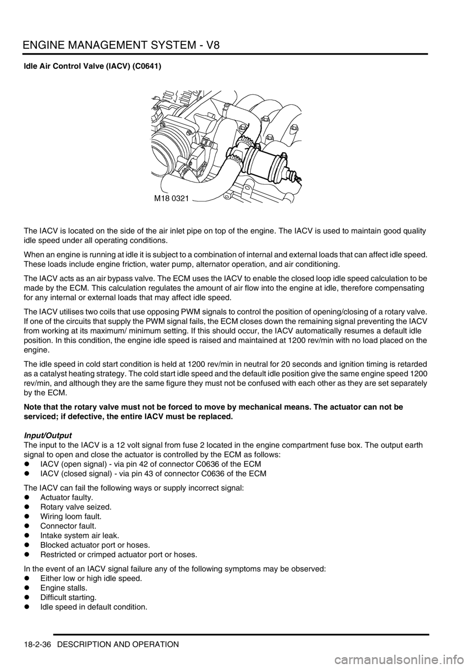
Idle Air Control Valve (IACV) (C0641)
The IACV is located on the side of the air inlet pipe on top of the engine. The IACV is used to maintain good quality
idle speed under all operating conditions.
When an engine is running at idle it is subject to a combination of internal and external loads that can affect idle speed.
These loads include engine friction, water pump, alternator operation, and air conditioning.
The IACV acts as an air bypass valve. The ECM uses the IACV to enable the closed loop idle speed calculation to be
made by the ECM. This calculation regulates the amount of air flow into the engine at idle, therefore compensating
for any internal or external loads that may affect idle speed.
The IACV utilises two coils that use opposing PWM signals to control the position of opening/closing of a rotary valve.
If one of the circuits that supply the PWM signal fails, the ECM closes down the remaining signal preventing the IACV
from working at its maximum/ minimum setting. If this should occur, the IACV automatically resumes a default idle
position. In this condition, the engine idle speed is raised and maintained at 1200 rev/min with no load placed on the
engine.
The idle speed in cold start condition is held at 1200 rev/min in neutral for 20 seconds and ignition timing is retarded
as a catalyst heating strategy. The cold start idle speed and the default idle position give the same engine speed 1200
rev/min, and although they are the same figure they must not be confused with each other as they are set separately
by the ECM.
Note that the rotary valve must not be forced to move by mechanical means. The actuator can not be
serviced; if defective, the entire IACV must be replaced.
Input/Output
The input to the IACV is a 12 volt signal from fuse 2 located in the engine compartment fuse box. The output earth
signal to open and close the actuator is controlled by the ECM as follows:
lIACV (open signal) - via pin 42 of connector C0636 of the ECM
lIACV (closed signal) - via pin 43 of connector C0636 of the ECM
The IACV can fail the following ways or supply incorrect signal:
lActuator faulty.
lRotary valve seized.
lWiring loom fault.
lConnector fault.
lIntake system air leak.
lBlocked actuator port or hoses.
lRestricted or crimped actuator port or hoses.
In the event of an IACV signal failure any of the following symptoms may be observed:
lEither low or high idle speed.
lEngine stalls.
lDifficult starting.
lIdle speed in default condition.
Page 337 of 1529
ENGINE MANAGEMENT SYSTEM - V8
18-2-38 DESCRIPTION AND OPERATION
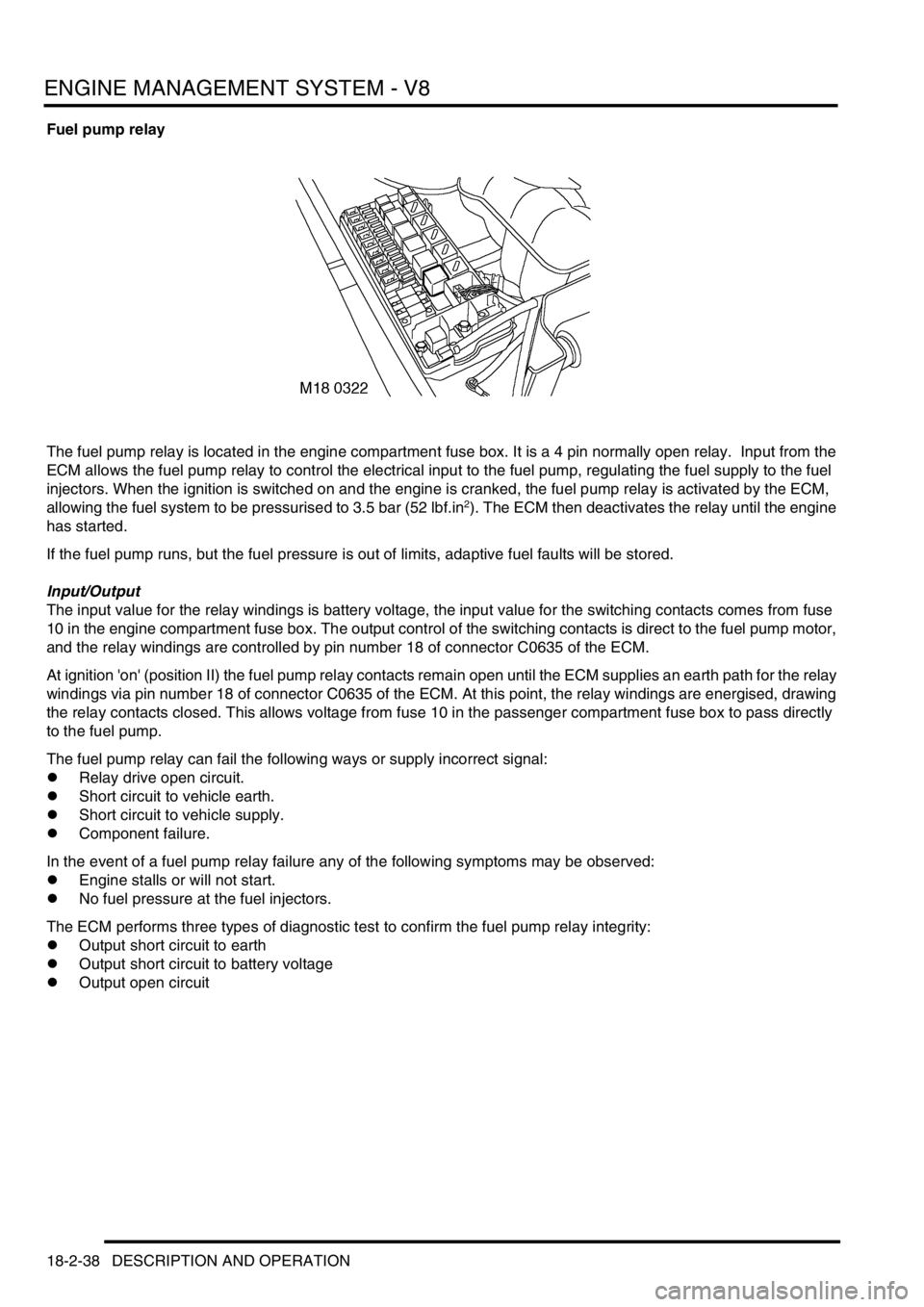
Fuel pump relay
The fuel pump relay is located in the engine compartment fuse box. It is a 4 pin normally open relay. Input from the
ECM allows the fuel pump relay to control the electrical input to the fuel pump, regulating the fuel supply to the fuel
injectors. When the ignition is switched on and the engine is cranked, the fuel pump relay is activated by the ECM,
allowing the fuel system to be pressurised to 3.5 bar (52 lbf.in
2). The ECM then deactivates the relay until the engine
has started.
If the fuel pump runs, but the fuel pressure is out of limits, adaptive fuel faults will be stored.
Input/Output
The input value for the relay windings is battery voltage, the input value for the switching contacts comes from fuse
10 in the engine compartment fuse box. The output control of the switching contacts is direct to the fuel pump motor,
and the relay windings are controlled by pin number 18 of connector C0635 of the ECM.
At ignition 'on' (position II) the fuel pump relay contacts remain open until the ECM supplies an earth path for the relay
windings via pin number 18 of connector C0635 of the ECM. At this point, the relay windings are energised, drawing
the relay contacts closed. This allows voltage from fuse 10 in the passenger compartment fuse box to pass directly
to the fuel pump.
The fuel pump relay can fail the following ways or supply incorrect signal:
lRelay drive open circuit.
lShort circuit to vehicle earth.
lShort circuit to vehicle supply.
lComponent failure.
In the event of a fuel pump relay failure any of the following symptoms may be observed:
lEngine stalls or will not start.
lNo fuel pressure at the fuel injectors.
The ECM performs three types of diagnostic test to confirm the fuel pump relay integrity:
lOutput short circuit to earth
lOutput short circuit to battery voltage
lOutput open circuit
Page 340 of 1529

ENGINE MANAGEMENT SYSTEM - V8
DESCRIPTION AND OPERATION 18-2-41
Input/Output
Input to the low tension side of the ignition coils comes from Fuse 14 located in the passenger compartment fuse box.
This fuse provides battery power for two ignition coils.
It is possible to test both primary and secondary coils of the ignition coils for resistance using a multimeter as follows:
lExpected primary coil resistance: 0.5 ± 0.05 Ω at 20 °C (68 °F).
lExpected secondary coil resistance: 13.3 ± 1.3 kΩ at 20 °C (68 °F).
The ECM provides the earth control for each coil on separate pins as follows:
LH Bank (cylinders 1, 3, 5, 7)
lCylinder 1 - pin 6 of connector C0638 of the ECM multiplug.
lCylinder 3 - pin 2 of connector C0638 of the ECM multiplug.
lCylinder 5 - pin 8 of connector C0638 of the ECM multiplug.
lCylinder 7 - pin 7 of connector C0638 of the ECM multiplug.
RH Bank (cylinders 2, 4, 6, 8)
lCylinder 2 - pin 2 of connector C0638 of the ECM multiplug.
lCylinder 4 - pin 7 of connector C0638 of the ECM multiplug.
lCylinder 6 - pin 6 of connector C0638 of the ECM multiplug.
lCylinder 8 - pin 8 of connector C0638 of the ECM multiplug.
The ignition coil can fail the following ways or supply incorrect signal:
lCoil open circuit.
lShort circuit to vehicle supply.
lShort circuit to vehicle earth.
lFaulty component.
In the event of ignition coil failure any of the following symptoms may be observed:
lEngine misfire on specific cylinders.
lEngine will not start.
Page 346 of 1529
ENGINE MANAGEMENT SYSTEM - V8
DESCRIPTION AND OPERATION 18-2-47
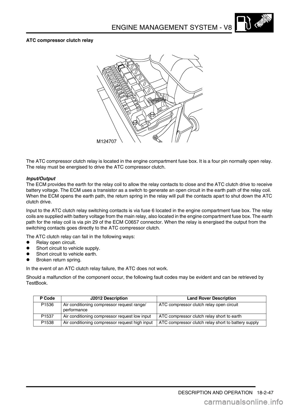
ATC compressor clutch relay
The ATC compressor clutch relay is located in the engine compartment fuse box. It is a four pin normally open relay.
The relay must be energised to drive the ATC compressor clutch.
Input/Output
The ECM provides the earth for the relay coil to allow the relay contacts to close and the ATC clutch drive to receive
battery voltage. The ECM uses a transistor as a switch to generate an open circuit in the earth path of the relay coil.
When the ECM opens the earth path, the return spring in the relay will pull the contacts apart to shut down the ATC
clutch drive.
Input to the ATC clutch relay switching contacts is via fuse 6 located in the engine compartment fuse box. The relay
coils are supplied with battery voltage from the main relay, also located in the engine compartment fuse box. The earth
path for the relay coil is via pin 29 of the ECM C0657 connector. When the relay is energised the output from the
switching contacts goes directly to the ATC compressor clutch.
The ATC clutch relay can fail in the following ways:
lRelay open circuit.
lShort circuit to vehicle supply.
lShort circuit to vehicle earth.
lBroken return spring.
In the event of an ATC clutch relay failure, the ATC does not work.
Should a malfunction of the component occur, the following fault codes may be evident and can be retrieved by
TestBook.
P Code J2012 Description Land Rover Description
P1536 Air conditioning compressor request range/
performanceATC compressor clutch relay open circuit
P1537 Air conditioning compressor request low input ATC compressor clutch relay short to earth
P1538 Air conditioning compressor request high input ATC compressor clutch relay short to battery supply