LAND ROVER DISCOVERY 2002 Workshop Manual
Manufacturer: LAND ROVER, Model Year: 2002, Model line: DISCOVERY, Model: LAND ROVER DISCOVERY 2002Pages: 1672, PDF Size: 46.1 MB
Page 1121 of 1672

RESTRAINT SYSTEMS
75-26 REPAIRS
6.Ensure airbag module mounting brackets are
secure.
7.Connect flylead SMD 4082/5 to airbag module.
WARNING: Ensure the deployment tool is
not connected to the battery.
8.Connect flylead SMD 4082/5 to tool SMD 4082/
1.
9.Connect tool SMD 4082/1 to battery.
WARNING: Ensure all personnel are at least
15 metres (50 ft) away from the airbag
module.10.Press both operating buttons to deploy airbag
module.
11.DO NOT return to airbag module for 30
minutes.
12.Using gloves and face mask, remove airbag
module from tool, place airbag module in
plastic bag and seal bag.
13.Wipe down tool with damp cloth.
14.Transport deployed airbag module to
designated area for incineration.
NOTE: DO NOT re-use or salvage any parts of
the airbag system.Do not transport deployed
SRS components in the vehicle passenger
compartment.
Page 1122 of 1672

RESTRAINT SYSTEMS
REPAIRS 75-27
Pre-tensioner - deployment
$% 76.74.99
These guidelines are written to aid authorised
personnel to carry out the safe disposal of pre-
tensioners.
If a vehicle is to be scrapped and contains an
undeployed pre-tensioner, the pre-tensioner
must be manually deployed. This operation
should only be carried out using the following
recommended manual deployment procedure.
Before deployment is started the deployment
tool self test procedure should be carried out.
WARNING: Only use approved deployment
equipment, and only deploy SRS components in
a well ventilated designated area. Ensure SRS
components are not damaged or ruptured before
deployment. Notify the relevant authorities.
Deploy
1.Carry out deployment tool self test.
+ RESTRAINT SYSTEMS, REPAIRS,
Airbag deployment tool - self test.
2.Slide seat fully rearwards to access pre-
tensioner harness connector.
3.Disconnect pre-tensioner harness connector.
Ensure deployment tool SMD 4082/1 is not
connected to battery.
4.Connect flylead SMD 4082/30 to pre-tensioner
connector.
5.Connect flylead SMD 4082/30 to tool SMD
4082/1
WARNING: Ensure pre-tensioner is secured
tightly to seat.
6.Connect tool SMD 4082/1 to battery.
WARNING: Ensure all personnel are
standing at least 15 metres 50 (ft) away from
vehicle.
7.Press both operating buttons to deploy pre-
tensioner.
8.Wearing gloves, disconnect flylead SMD 4082/
30 from pre-tensioner connector and remove
pre-tensioner from seat. Place pre-tensioner in
plastic bag and seal bag.
Page 1123 of 1672

RESTRAINT SYSTEMS
75-28 REPAIRS
9.Transport deployed pre-tensioner to
designated area for incineration.
NOTE: DO NOT transport pre-tensioner in the
vehicle passenger compartment. DO NOT re-
use or salvage any parts of the airbag system.
If the vehicle is being scrapped, scrap all
remaining parts of airbag system.
Page 1124 of 1672
DOORS
REPAIRS 76-1-1
DOORS REPAIRS
Door - front
$% 76.28.01.99
Remove
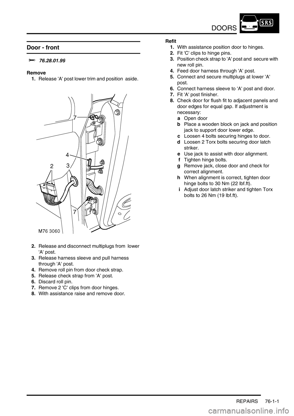
1.Release 'A' post lower trim and position aside.
2.Release and disconnect multiplugs from lower
'A' post.
3.Release harness sleeve and pull harness
through 'A' post.
4.Remove roll pin from door check strap.
5.Release check strap from 'A' post.
6.Discard roll pin.
7.Remove 2 'C' clips from door hinges.
8.With assistance raise and remove door. Refit
1.With assistance position door to hinges.
2.Fit 'C' clips to hinge pins.
3.Position check strap to 'A' post and secure with
new roll pin.
4.Feed door harness through 'A' post.
5.Connect and secure multiplugs at lower 'A'
post.
6.Connect harness sleeve to 'A' post and door.
7.Fit 'A' post finisher.
8.Check door for flush fit to adjacent panels and
door edges for equal gap. If adjustment is
necessary:
aOpen door
bPlace a wooden block on jack and position
jack to support door lower edge.
cLoosen 4 bolts securing hinges to door.
dLoosen 2 Torx bolts securing door latch
striker.
eUse jack to assist with door alignment.
fTighten hinge bolts.
gRemove jack, close door and check for
correct alignment.
hWhen alignment is correct, tighten door
hinge bolts to 30 Nm (22 lbf.ft).
iAdjust door latch striker and tighten Torx
bolts to 26 Nm (19 lbf.ft).
Page 1125 of 1672
DOORS
76-1-2 REPAIRS
Door - rear
$% 76.28.02.99
Remove
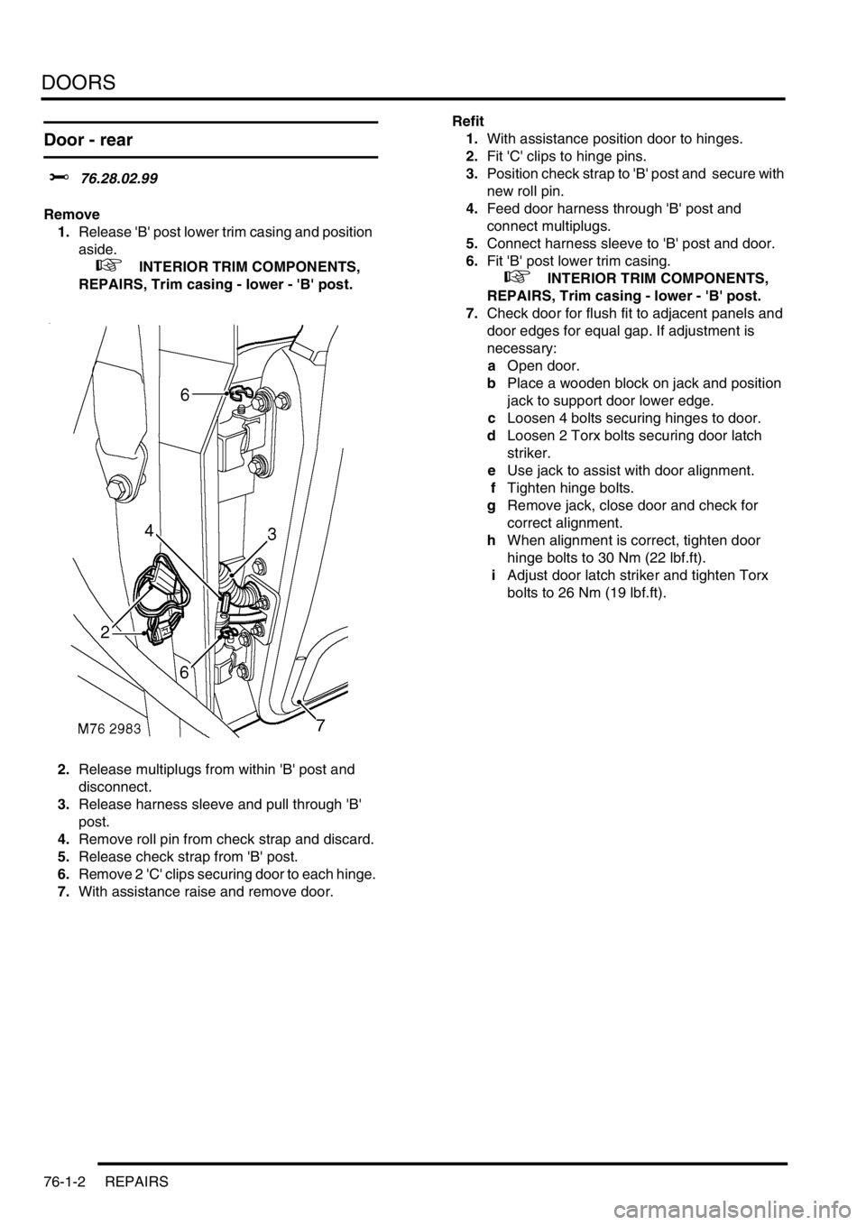
1.Release 'B' post lower trim casing and position
aside.
+ INTERIOR TRIM COMPONENTS,
REPAIRS, Trim casing - lower - 'B' post.
2.Release multiplugs from within 'B' post and
disconnect.
3.Release harness sleeve and pull through 'B'
post.
4.Remove roll pin from check strap and discard.
5.Release check strap from 'B' post.
6.Remove 2 'C' clips securing door to each hinge.
7.With assistance raise and remove door. Refit
1.With assistance position door to hinges.
2.Fit 'C' clips to hinge pins.
3.Position check strap to 'B' post and secure with
new roll pin.
4.Feed door harness through 'B' post and
connect multiplugs.
5.Connect harness sleeve to 'B' post and door.
6.Fit 'B' post lower trim casing.
+ INTERIOR TRIM COMPONENTS,
REPAIRS, Trim casing - lower - 'B' post.
7.Check door for flush fit to adjacent panels and
door edges for equal gap. If adjustment is
necessary:
aOpen door.
bPlace a wooden block on jack and position
jack to support door lower edge.
cLoosen 4 bolts securing hinges to door.
dLoosen 2 Torx bolts securing door latch
striker.
eUse jack to assist with door alignment.
fTighten hinge bolts.
gRemove jack, close door and check for
correct alignment.
hWhen alignment is correct, tighten door
hinge bolts to 30 Nm (22 lbf.ft).
iAdjust door latch striker and tighten Torx
bolts to 26 Nm (19 lbf.ft).
Page 1126 of 1672
DOORS
REPAIRS 76-1-3
Door - tail
$% 76.28.19.99
Remove
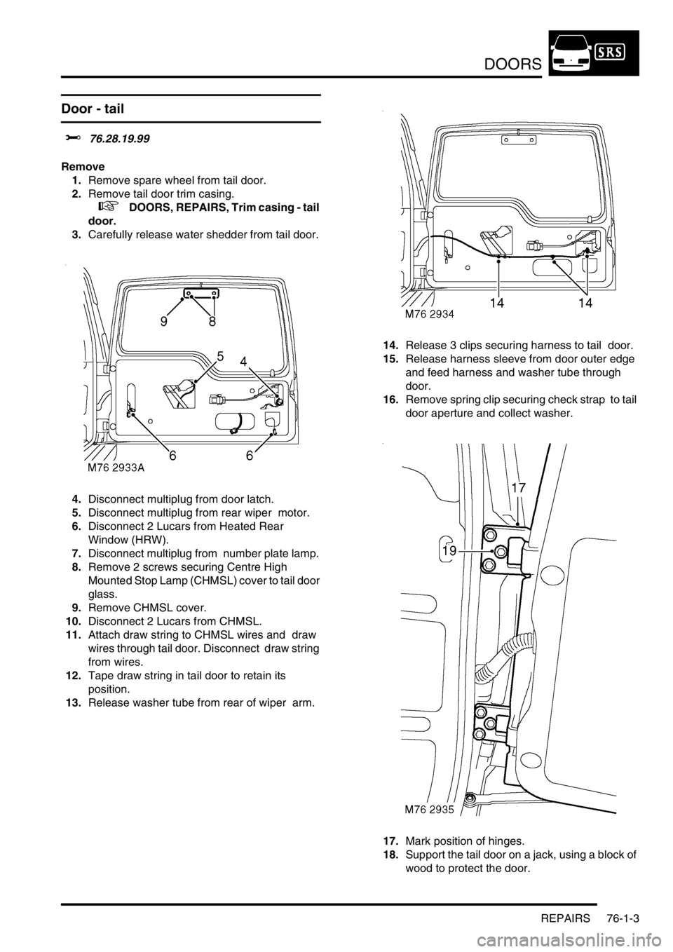
1.Remove spare wheel from tail door.
2.Remove tail door trim casing.
+ DOORS, REPAIRS, Trim casing - tail
door.
3.Carefully release water shedder from tail door.
4.Disconnect multiplug from door latch.
5.Disconnect multiplug from rear wiper motor.
6.Disconnect 2 Lucars from Heated Rear
Window (HRW).
7.Disconnect multiplug from number plate lamp.
8.Remove 2 screws securing Centre High
Mounted Stop Lamp (CHMSL) cover to tail door
glass.
9.Remove CHMSL cover.
10.Disconnect 2 Lucars from CHMSL.
11.Attach draw string to CHMSL wires and draw
wires through tail door. Disconnect draw string
from wires.
12.Tape draw string in tail door to retain its
position.
13.Release washer tube from rear of wiper arm. 14.Release 3 clips securing harness to tail door.
15.Release harness sleeve from door outer edge
and feed harness and washer tube through
door.
16.Remove spring clip securing check strap to tail
door aperture and collect washer.
17.Mark position of hinges.
18.Support the tail door on a jack, using a block of
wood to protect the door.
Page 1127 of 1672

DOORS
76-1-4 REPAIRS
19.Remove 6 bolts securing tail door hinges to
body and, with assistance, remove tail door.
Refit
1.Support the tail door on a jack, using a block of
wood to protect the door.
2.With assistance position door. Fit securing
bolts but do not tighten at this stage.
3.Fit washer and spring clip securing check strap
to aperture.
4.Adjust position of tail door in relation to
aperture, ensuring gaps around all 4 edges
are consistent, and door closes cleanly onto
dove tail.
5.When tail door is correctly adjusted, tighten tail
door hinge bolts to 34 Nm (25 lbf.ft).
6.Feed harness and washer tube through outer
edge of door and connect harness sleeve to
door.
7.Secure harness to tail door with clips.
8.Connect washer tube to rear of wiper arm.
9.Remove tape from draw string and secure to
CHMSL wires.
10.Draw wires through tail door and connect
Lucars to CHMSL.
11.Fit CHMSL cover and secure with screws.
12.Connect multiplug of number plate lamp.
13.Connect Lucars to HRW.
14.Connect multiplug to rear wiper motor.
15.Connect multiplug to door latch.
16.Fit water shedder to door.
17.Fit tail door trim casing.
+ DOORS, REPAIRS, Trim casing - tail
door.
18.Fit spare wheel to tail door.
Glass - front or rear door
$% 76.31.01
Remove
1.Remove door trim casing.
+ DOORS, REPAIRS, Trim casing -
front door.
+ DOORS, REPAIRS, Trim casing -
rear door.
2.Carefully release water shedder from door.
3. Front door glass only: Remove exterior door
mirror.
+ EXTERIOR FITTINGS, REPAIRS,
Mirror - exterior - electric.
4.Remove inner waist seal.
Front door shown, rear door similar
5.Remove 2 clips securing ends of outer waist
seal.
6.Remove outer waist seal.
7.Remove 2 bolts securing glass to regulator. If
necessary, lower glass to access bolts.
8.Remove bolts securing frame to door.
9.Remove door frame complete with glass.
10.Slide out and remove glass from frame.
Page 1128 of 1672

DOORS
REPAIRS 76-1-5
Refit
1.Fit glass to frame.
2.Position frame to door and tighten bolts
securing front door frame to 10 Nm (7 lbf.ft) and
bolts securing rear door frame to 22 Nm (16
lbf.ft).
3.Secure regulator to glass with bolts and tighten
to 6 Nm (4.4 lbf.ft).
4.Fit inner and outer waist seal and secure with
clips.
5. Front door glass only: Fit exterior door mirror.
+ EXTERIOR FITTINGS, REPAIRS,
Mirror - exterior - electric.
6.Fit water shedder to door.
7.Fit door trim casing.
+ DOORS, REPAIRS, Trim casing -
front door.
+ DOORS, REPAIRS, Trim casing -
rear door.
Quarter light
$% 76.31.31
Remove
1.Remove rear door glass.
+ DOORS, REPAIRS, Glass - front or
rear door.
2.Remove 2 bolts securing quarter light glass to
frame.
3.Remove quarter light glass from frame.
Refit
1.Fit quarter light glass to frame.
2.Fit bolts securing quarter light glass to frame
and tighten to 10 Nm (7 lbf.ft).
3.Fit rear door glass.
+ DOORS, REPAIRS, Glass - front or
rear door.
Page 1129 of 1672
DOORS
76-1-6 REPAIRS
Regulator and motor - front and rear
door glass
$% 76.31.45
Remove
1.Remove door trim casing.
+ DOORS, REPAIRS, Trim casing -
front door.
+ DOORS, REPAIRS, Trim casing -
rear door.
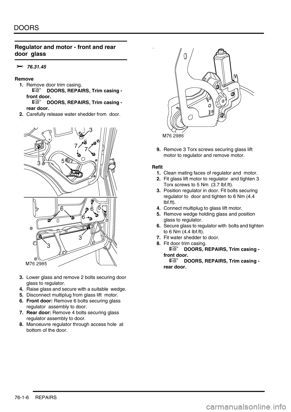
2.Carefully release water shedder from door.
3.Lower glass and remove 2 bolts securing door
glass to regulator.
4.Raise glass and secure with a suitable wedge.
5.Disconnect multiplug from glass lift motor.
6. Front door: Remove 6 bolts securing glass
regulator assembly to door.
7. Rear door: Remove 4 bolts securing glass
regulator assembly to door.
8.Manoeuvre regulator through access hole at
bottom of the door. 9.Remove 3 Torx screws securing glass lift
motor to regulator and remove motor.
Refit
1.Clean mating faces of regulator and motor.
2.Fit glass lift motor to regulator and tighten 3
Torx screws to 5 Nm (3.7 lbf.ft).
3.Position regulator in door. Fit bolts securing
regulator to door and tighten to 6 Nm (4.4
lbf.ft).
4.Connect multiplug to glass lift motor.
5.Remove wedge holding glass and position
glass to regulator.
6.Secure glass to regulator with bolts and tighten
to 6 Nm (4.4 lbf.ft).
7.Fit water shedder to door.
8.Fit door trim casing.
+ DOORS, REPAIRS, Trim casing -
front door.
+ DOORS, REPAIRS, Trim casing -
rear door.
Page 1130 of 1672
DOORS
REPAIRS 76-1-7
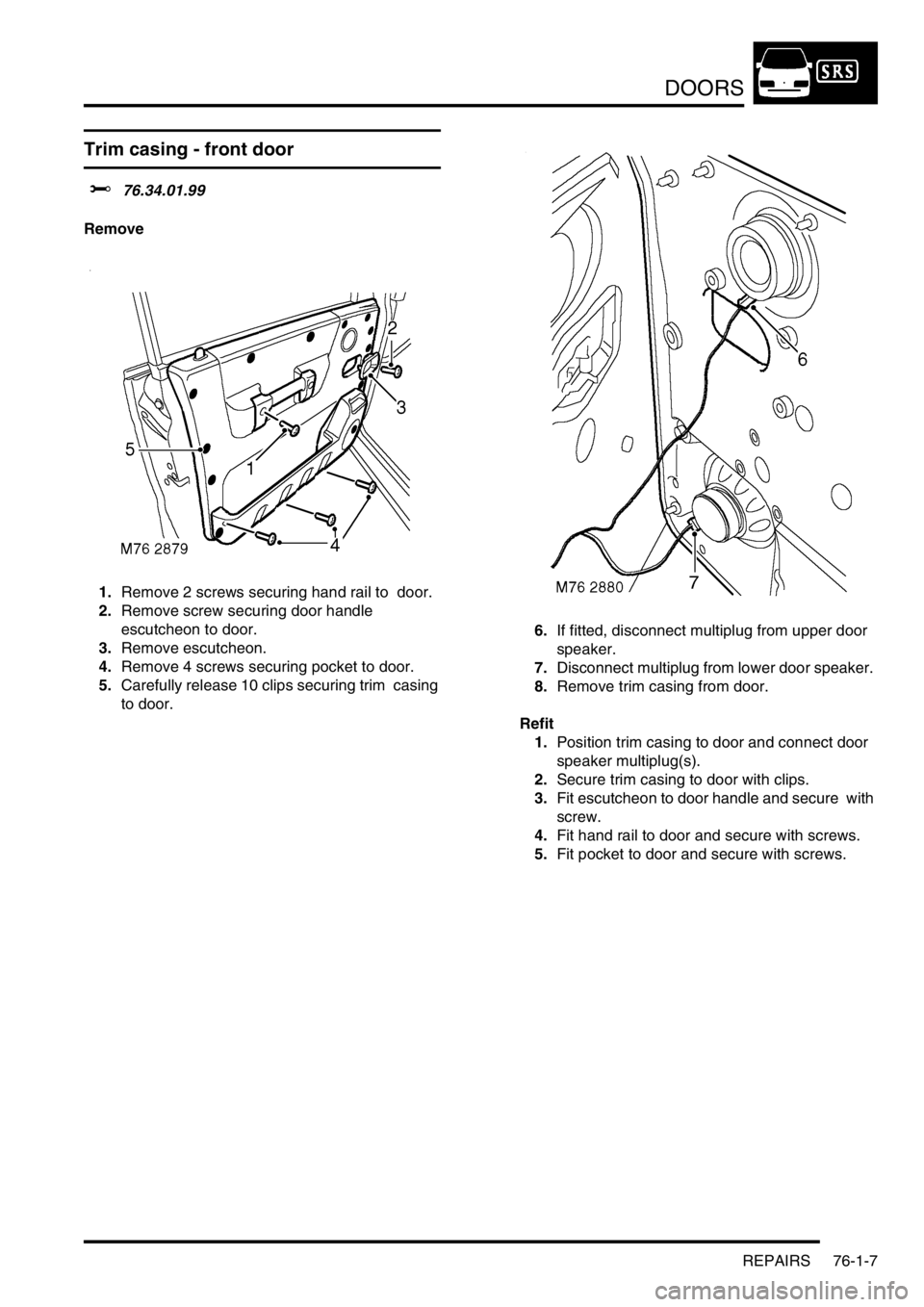
Trim casing - front door
$% 76.34.01.99
Remove
1.Remove 2 screws securing hand rail to door.
2.Remove screw securing door handle
escutcheon to door.
3.Remove escutcheon.
4.Remove 4 screws securing pocket to door.
5.Carefully release 10 clips securing trim casing
to door. 6.If fitted, disconnect multiplug from upper door
speaker.
7.Disconnect multiplug from lower door speaker.
8.Remove trim casing from door.
Refit
1.Position trim casing to door and connect door
speaker multiplug(s).
2.Secure trim casing to door with clips.
3.Fit escutcheon to door handle and secure with
screw.
4.Fit hand rail to door and secure with screws.
5.Fit pocket to door and secure with screws.