light LAND ROVER DISCOVERY 2002 Workshop Manual
[x] Cancel search | Manufacturer: LAND ROVER, Model Year: 2002, Model line: DISCOVERY, Model: LAND ROVER DISCOVERY 2002Pages: 1672, PDF Size: 46.1 MB
Page 1311 of 1672

BODY SEALING MATERIALS
77-3-4 MATERIALS AND APPLICATIONS
Application equipment
Manufacturers and suppliers
Suitable application equipment is available from the following manufacturers and suppliers:
3M
Automotive Trades Group
3M UK Plc
3M House
PO Box 1
Market Place
Bracknell
Berks
RG 12 1JU
( (01344) 858611
Cooper Pegler
Burgess Hill
Sussex
RH15 9LA
( (014 446) 42526
SATA Spray Equipment
Minden Industrial Ltd
16 Greyfriars Road
Moreton Hall
Bury St. Edmunds
Suffolk
IP32 7DX
( (01284) 760791
3M Body Schutz Pistol Spraygun 08996
A pistol type spraygun constructed from case and machined light alloy and designed for use with 3M screw fit Body
Schutz containers.
3M Caulking Gun MKIII 8002
A lightweight, robust metal skeleton gun designed to accept 325 mm (13 in) cartridge for dispensing sealants etc. This
gun provides rapid cartridge insertion and loading, with a quick-release lever for accurate control of material ejection
and shut-off.
3M Pneumatic Cartridge Gun 08012
Air line-fed gun for applying 3M cartridge products. Excellent for ease of application to obtain a smooth bead.
Regulator valve for additional control.
3M Pneumatic Applicator Guns
Air line-fed gun for application of 3M sachet sealers (Part Number 08006 for 200 ml and 310 ml sachet applications,
and Part Number 08007 for all size sachets including 600 ml).
Also available: Heavy Duty Manual Gun 08013.
3M Applicator Gun 08190.
For the application of 3M Structural Adhesive 08120.
3M Inner Cavity Wax Applicator Gun 08997
This equipment accepts 1-litre canisters and has a 750 mm (29.572 in) flexible tube.
The approved system is available from all 3M refinishing factors.
Page 1375 of 1672

AIR CONDITIONING
82-2DESCRIPTION AND OPERATION
A/C control system component layout
RH drive shown, LH drive similar
1Air temperature control ECU
2Heater coolant temperature sensor
3Evaporator temperature sensor
4Dual pressure switch
5Ambient temperature sensor
6Sunlight sensor
7In-car temperature sensor
Page 1385 of 1672

AIR CONDITIONING
82-12DESCRIPTION AND OPERATION
Control system
The control system operates the refrigerant system and the control flaps in the heater assembly to control the
temperature and distribution of air in the vehicle interior. It also outputs signals to the fresh/recirculated air servo motor
and the blower to control the volume and source of inlet air. The control system consists of:
lAn Air Temperature Control (ATC) ECU.
lA dual pressure switch.
lAn evaporator temperature sensor.
lAn in-car temperature sensor.
lA sunlight sensor.
lA heater coolant temperature sensor.
lAn ambient temperature sensor.
ATC ECU
The ATC ECU is installed in the centre of the fascia, below the radio. An integral control panel on the ATC ECU
contains switches for system control inputs and a LCD to provide system status information.
Inputs from sensors and the control panel switches are processed by the ATC ECU, which then outputs the
appropriate control signals.
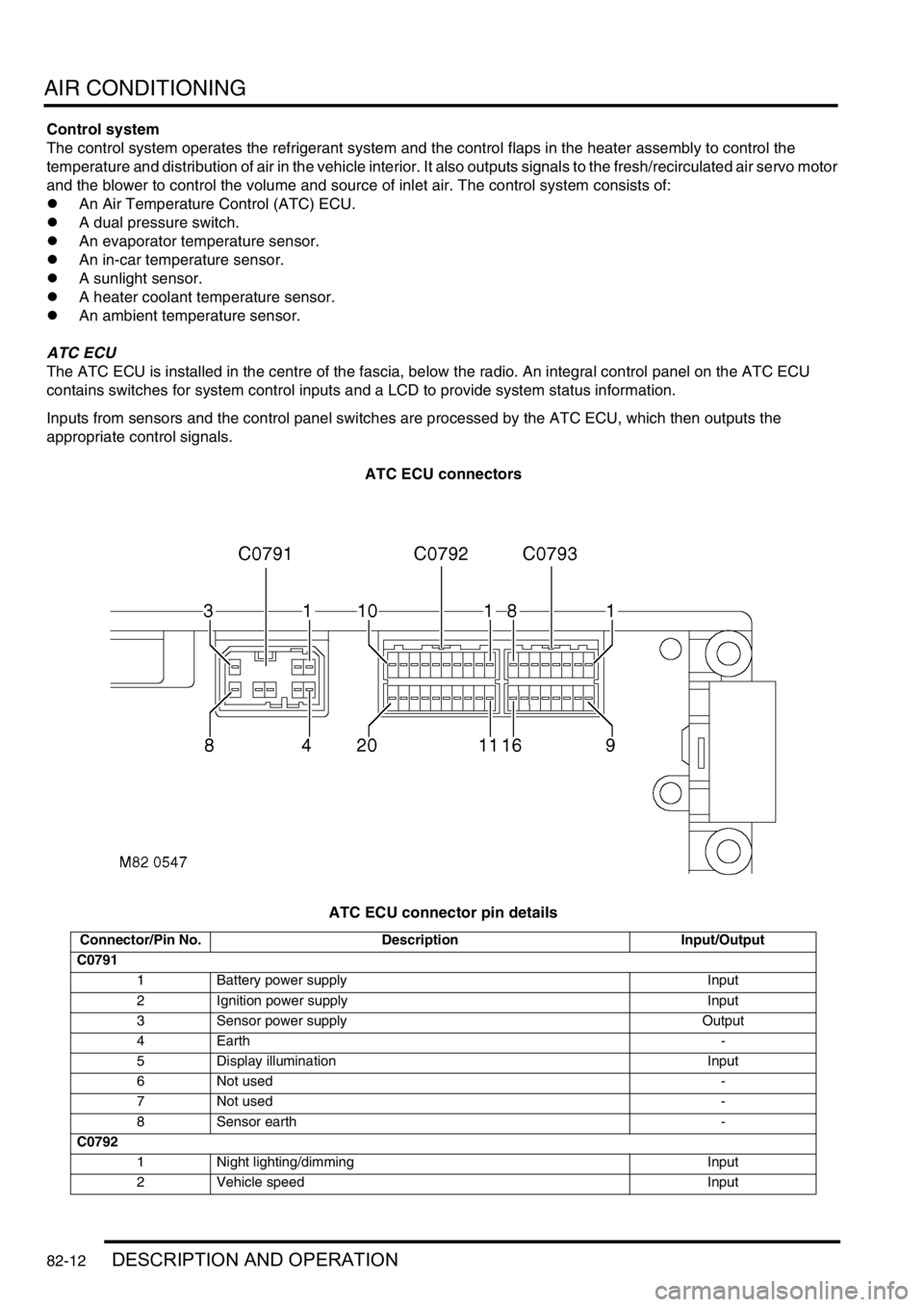
ATC ECU connectors
ATC ECU connector pin details
Connector/Pin No. Description Input/Output
C0791
1 Battery power supply Input
2 Ignition power supply Input
3 Sensor power supply Output
4Earth-
5 Display illumination Input
6 Not used-
7 Not used-
8 Sensor earth -
C0792
1 Night lighting/dimming Input
2 Vehicle speed Input
Page 1389 of 1672

AIR CONDITIONING
82-16DESCRIPTION AND OPERATION
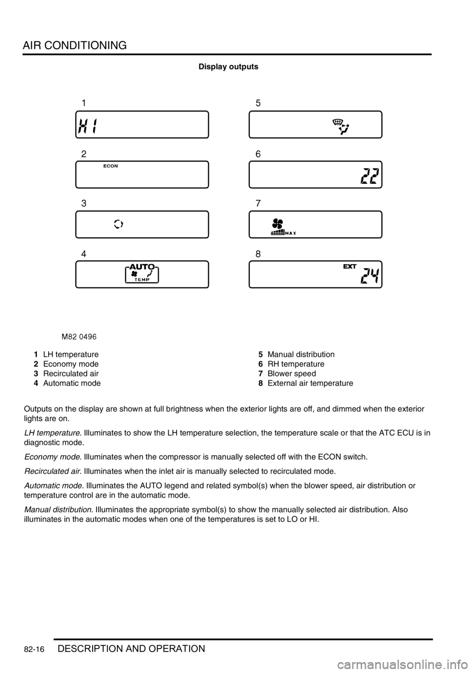
Display outputs
1LH temperature
2Economy mode
3Recirculated air
4Automatic mode5Manual distribution
6RH temperature
7Blower speed
8External air temperature
Outputs on the display are shown at full brightness when the exterior lights are off, and dimmed when the exterior
lights are on.
LH temperature. Illuminates to show the LH temperature selection, the temperature scale or that the ATC ECU is in
diagnostic mode.
Economy mode. Illuminates when the compressor is manually selected off with the ECON switch.
Recirculated air. Illuminates when the inlet air is manually selected to recirculated mode.
Automatic mode. Illuminates the AUTO legend and related symbol(s) when the blower speed, air distribution or
temperature control are in the automatic mode.
Manual distribution. Illuminates the appropriate symbol(s) to show the manually selected air distribution. Also
illuminates in the automatic modes when one of the temperatures is set to LO or HI.
Page 1390 of 1672

AIR CONDITIONING
DESCRIPTION AND OPERATION 82-17
RH temperature. Illuminates to show the RH temperature selection, external air temperature or diagnostic fault code.
Blower speed. Illuminates when the blower speed is manually selected. Also illuminates in the automatic modes when
one of the temperatures is set to LO or HI.
External air temperature. EXT illuminates to show that external air temperature is selected on.
All temperature indications on the display are in either
°C or °F. For 1 second after the system is first switched on, the
display shows only
°C or °F, in the LH temperature window, to indicate which temperature scale is in use. After 1
second, the
°C or °F indication goes off and the display shows all relevant outputs.
Temperature conversion: While the system is on, the temperature indications on the display can be switched between
the two scales by pressing and holding the fresh/recirculated air switch, then pressing and holding the A/C on/off
switch until the audible warning sounds (approximately 3 seconds).
Dual pressure switch
The dual pressure switch protects the refrigerant system from extremes of pressure. The normally closed switch is
installed in the top of the receiver drier. If minimum or maximum pressure limits are exceeded the switch contacts
open, causing the compressor clutch to be disengaged. The minimum pressure limit protects the compressor, by
preventing operation of the system unless there is a minimum refrigerant pressure (and thus refrigerant and
lubricating oil) in the system. The maximum pressure limit keeps the refrigerant system within a safe operating
pressure.
Dual pressure switch nominal operating pressures
Evaporator temperature sensor
The evaporator temperature sensor is an encapsulated thermistor that provides the ATC ECU with an input of the
evaporator air outlet temperature. The evaporator temperature sensor is installed in a clip which locates in the
evaporator matrix in the heater assembly. The ATC ECU uses the input to prevent the formation of ice on the
evaporator.
In-car temperature sensor
The in-car temperature sensor is an encapsulated thermistor that provides the ATC ECU with an input of cabin air
temperature. The sensor is integrated into the inlet of an electric fan, which is installed behind a grille in the fascia
outboard of the steering column. The fan runs continuously, while the ignition is on, to draw air through the grille and
across the sensor.
Sunlight sensor
The sunlight sensor consists of two diodes that provide the ATC ECU with inputs of light intensity, one as sensed
coming from the left of the vehicle and one as sensed coming from the right. The inputs are used as a measure of the
solar heating effect on vehicle occupants. The sensor is installed in the centre of the fascia upper surface.
Heater coolant temperature sensor
The heater coolant temperature sensor is an encapsulated thermistor that provides the ATC ECU with an input related
to heater matrix coolant temperature. The sensor is installed in the casing of the heater assembly and presses against
the end tank of the heater matrix.
Ambient temperature sensor
The ambient temperature sensor is an encapsulated thermistor that provides the ATC ECU with an input of external
air temperature. The sensor is attached to the cooling fan mounting bracket in front of the condenser.
Limit Opening pressure, bar (lbf.in2) Closing pressure, bar (lbf.in2)
Minimum 2.0 (29.0), pressure decreasing 2.3 (33.4), pressure increasing
Maximum 32 (464), pressure increasing 26 (377), pressure decreasing
Page 1394 of 1672

AIR CONDITIONING
DESCRIPTION AND OPERATION 82-21
Diagnostics
The ATC ECU performs a diagnostic check each time the ignition is switched on. To avoid nuisance fault indications
at low light levels, the sunlight sensor is omitted from the diagnostic check. If a fault is detected, the audible warning
sounds three times and the AUTO window on the control panel display flashes for 20 seconds. The ATC ECU then
reverts to normal control but uses a default value or strategy for the detected fault. Faults are identified by performing
a manual diagnostic check of the system.
A manual diagnostic check includes a check of the sunlight sensor, and is initiated by pressing and holding the AUTO
switch and the air distribution switch, then turning the ignition switch from off to on. The audible warning sounds once
and the indications on the control panel display illuminate. FC is shown in the LH temperature window and the results
of the check are shown as a two digit fault code in the RH temperature window. If a fault is detected, the audible
warning sounds three times and the AUTO window on the display flashes on and off for 20 seconds. If more than one
fault is detected, the fault codes cycle in numerical order, at 1 Hz. The audible warning sounds as each fault code is
shown. In low light conditions, to avoid false sunlight sensor fault indications, the sunlight sensor should be illuminated
with a strong light source.
Diagnostic fault codes and fault descriptions
Code Component Fault Default value/strategy
00 - No fault found -
11 In-car temperature sensor Open or short circuit 25°C (77°F)
12 Ambient temperature sensor Open or short circuit 10°C (50°F)
Cooling fan permanently on
Display shows "- -" if external
air temperature selected
13 Thermistor Open or short circuit 0°C (32°F)
14 Heater coolant temperature sensor Open or short circuit 70°C (158°F)
21 Sunlight sensor, left output Open or short circuit No solar heating correction
22 Sunlight sensor, right output Open or short circuit No solar heating correction
31 LH temperature servo motor Open or short circuit
Motor or flap mechanism seizedServo motor locked in position
32 RH temperature servo motor Open or short circuit
Motor or flap mechanism seizedServo motor locked in position
33 Distribution servo motor Open or short circuit
Motor or flap mechanism seizedServo motor locked in position
Page 1411 of 1672

AIR CONDITIONING
82-38REPAIRS
Sensor - ambient air temperature
$% 82.20.91
Remove
1.Remove front grille.
+ EXTERIOR FITTINGS, REPAIRS,
Grille - front - up to 03MY.
2.Release ambient air temperature sensor from
support bracket, disconnect multiplug and
remove sensor.
Refit
1.Position sensor, connect multiplug and secure
sensor to support bracket
2.Fit front grille.
+ EXTERIOR FITTINGS, REPAIRS,
Grille - front - up to 03MY.
Sensor - solar light
$% 82.20.92
Remove
1.Carefully remove solar light sensor from fascia.
2.Disconnect multiplug from solar light sensor.
3.Remove solar light sensor.
Refit
1.Connect multiplug to solar light sensor.
2.Position solar light sensor to fascia and push to
secure.
Page 1438 of 1672

WIPERS AND WASHERS
DESCRIPTION AND OPERATION 84-17
Front flick wipe
Flick wipe operation will only activate when the following conditions are met:
lIgnition switch is in position I or II.
lFront flick switch is operated.
Pressing the flick wipe switch operates the front wiper motor at high speed. The front wiper motor operates as long
as the flick switch is activated. Releasing the flick switch causes the front wiper motor to run through the park switch
circuitry. The park switch only permits low speed operation. Thus if the flick switch is pressed and immediately
released, the wipers operate at low speed.
Rear intermittent wipe variable delay
The rear intermittent wipe variable delay operation allows the driver to adjust the interval between wipes to suit local
conditions. Rear variable delay operation only activates if the following conditions are met:
lIgnition switch in position I or II.
lFront wash/ wipe switch on intermittent.
lRear wipe switch is operated.
The BCU determines the desired delay interval based on the setting of the variable delay switch. The rear wash/ wipe
delay is nominally twice as long as that of the front. This information passes from the IDM to the rear wiper relay and
activates the rear wiper motor.
If the delay duration is decreased during operation of the rear wiper, the wipers immediately operate once and the
delay cycle is reset.
If the delay duration is increased during operation of the rear wiper, the delay cycle is automatically increased by the
BCU.
Reverse wiping
Reverse wiping operates the rear wiper motor when reverse gear is selected. The transmission must be in reverse
for longer then 0.5 seconds before reversing wipe activates. Reversing wipe activates if the following conditions are
met:
lIgnition switch is in position II.
lReverse gear is selected.
lRear wiper or front wipers operating.
If the rear wiper is active in any mode when reverse gear is selected, the rear wiper activates for 4 second. After 4
seconds the rear wiper operates in a delay operation at the same delay interval set by the variable delay switch until
reverse gear is deselected.
If the front wipers are operating on either low or high speed when reverse gear is selected, the rear wiper activates
continuously until reverse gear is deselected.
In order to enable reversing wipe functions, the BCU utilises the reversing light switch located within the transmission
to determine when reverse gear has been selected.
If the front intermittent wipe is active when reverse gear is selected, the rear wiper completes 2 cycles before operating
at the same intermittent delay as the front wipers.
Page 1456 of 1672

LIGHTING
ADJUSTMENTS 86-2-1
LIGHTING ADJUST ME NTS
Headlamps beam alignment - up to 03MY
$% 86.40.17
Check
1.Ensure vehicle is unladen and tyres are at
correct pressures.
2. Models with SLS: Ensure vehicle is at
standard ride height.
3. Models with headlamp levelling: Ensure
headlamp levelling switch is set to '0'.
4.Align suitable beam setting equipment to
headlamp.
5.Switch headlamps on and measure main beam
settings. Beam must be 1.4% below the
horizontal and parallel to the vehicle centre line.
If necessary, adjust headlamp to get correct
beam settings.
6.Align beam setting equipment to 2nd headlamp
and repeat check.
7.Switch off headlamps and remove beam setting
equipment.
Adjust
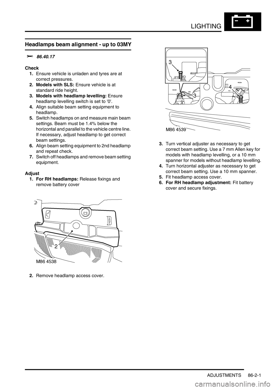
1. For RH headlamps: Release fixings and
remove battery cover
2.Remove headlamp access cover.3.Turn vertical adjuster as necessary to get
correct beam setting. Use a 7 mm Allen key for
models with headlamp levelling, or a 10 mm
spanner for models without headlamp levelling.
4.Turn horizontal adjuster as necessary to get
correct beam setting. Use a 10 mm spanner.
5.Fit headlamp access cover.
6. For RH headlamp adjustment: Fit battery
cover and secure fixings.
Page 1457 of 1672

LIGHTING
86-2-2 ADJUSTMENTS
Headlamps beam alignment - from 03MY
$% 86.40.17
Check
1.Ensure vehicle is unladen and tyres are set at
the correct pressures.
2. Models with SLS: Ensure vehicle is at the
standard ride height.
3. Models without SLS: Set headlamp leveling
switch to zero.
4.Align beam setting equipment to headlamp.
5.Switch on headlamps. Headlamp setting 1.2%
below horizontal and parallel.
6.Align beam setting equipment to second
headlamp and repeat the check.
Adjust
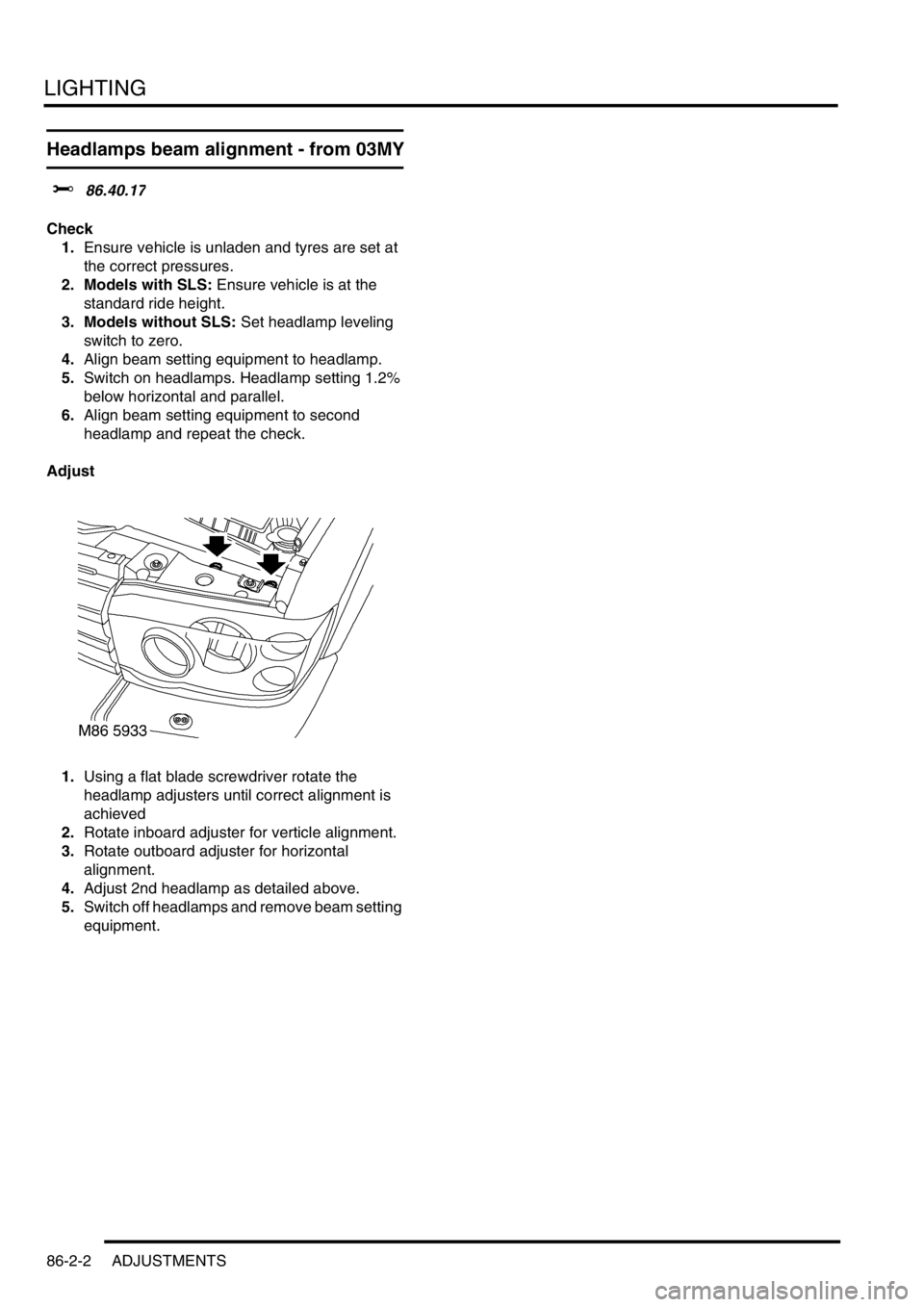
1.Using a flat blade screwdriver rotate the
headlamp adjusters until correct alignment is
achieved
2.Rotate inboard adjuster for verticle alignment.
3.Rotate outboard adjuster for horizontal
alignment.
4.Adjust 2nd headlamp as detailed above.
5.Switch off headlamps and remove beam setting
equipment.