engine coolant LAND ROVER DISCOVERY 2002 Owner's Manual
[x] Cancel search | Manufacturer: LAND ROVER, Model Year: 2002, Model line: DISCOVERY, Model: LAND ROVER DISCOVERY 2002Pages: 1672, PDF Size: 46.1 MB
Page 178 of 1672
ENGINE - TD5
REPAIRS 12-1-39
Gasket - cylinder head
$% 12.29.02
Remove
Note: The following procedures cover engines
fitted with or without an EGR cooler. The EGR
cooler is bolted to the front of the cylinder head.
1.Remove bonnet.
+ EXTERIOR FITTINGS, REPAIRS,
Bonnet.
2.Release turnbuckles and remove battery cover.
3.Disconnect battery earth lead.
4.Drain cooling system.
+ COOLING SYSTEM - Td5,
ADJUSTMENTS, Drain and refill.
5.Remove camshaft cover gasket.
+ ENGINE - Td5, REPAIRS, Gasket -
cover - camshaft.
6.Remove cooling fan coupling.
+ COOLING SYSTEM - Td5, REPAIRS,
Fan - viscous.
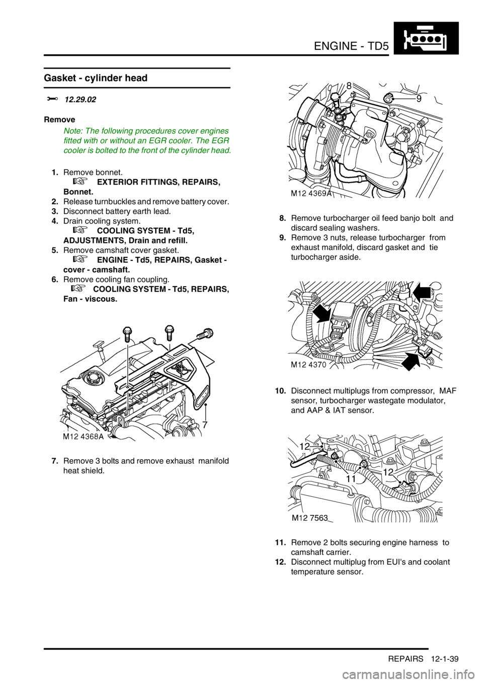
7.Remove 3 bolts and remove exhaust manifold
heat shield. 8.Remove turbocharger oil feed banjo bolt and
discard sealing washers.
9.Remove 3 nuts, release turbocharger from
exhaust manifold, discard gasket and tie
turbocharger aside.
10.Disconnect multiplugs from compressor, MAF
sensor, turbocharger wastegate modulator,
and AAP & IAT sensor.
11.Remove 2 bolts securing engine harness to
camshaft carrier.
12.Disconnect multiplug from EUI's and coolant
temperature sensor.
Page 179 of 1672
ENGINE - TD5
12-1-40 REPAIRS
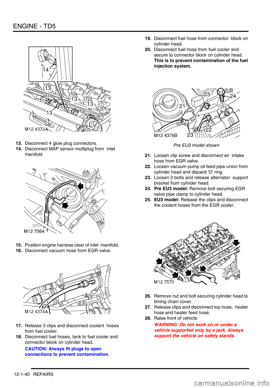
13.Disconnect 4 glow plug connectors.
14.Disconnect MAP sensor multiplug from inlet
manifold.
15.Position engine harness clear of inlet manifold.
16.Disconnect vacuum hose from EGR valve.
17.Release 3 clips and disconnect coolant hoses
from fuel cooler.
18.Disconnect fuel hoses, tank to fuel cooler and
connector block on cylinder head.
CAUTION: Always fit plugs to open
connections to prevent contamination.19.Disconnect fuel hose from connector block on
cylinder head.
20.Disconnect fuel hose from fuel cooler and
secure to connector block on cylinder head.
This is to prevent contamination of the fuel
injection system.
Pre EU3 model shown
21.Loosen clip screw and disconnect air intake
hose from EGR valve.
22.Loosen vacuum pump oil feed pipe union from
cylinder head and discard 'O' ring.
23.Loosen 2 bolts and release alternator support
bracket from cylinder head.
24. Pre EU3 model: Remove bolt securing EGR
valve pipe clamp to cylinder head.
25. EU3 model: Release the clips and disconnect
the coolant hoses from the EGR cooler.
26.Remove nut and bolt securing cylinder head to
timing chain cover.
27.Release clips and disconnect top hose, heater
hose and heater feed hose.
28.Raise front of vehicle.
WARNING: Do not work on or under a
vehicle supported only by a jack. Always
support the vehicle on safety stands.
Page 181 of 1672

ENGINE - TD5
12-1-42 REPAIRS
37.Using suitable lifting chains and tool LRT-12-
138 carefully remove cylinder head and place
on wooden blocks or stands.
CAUTION: Support both ends of cylinder
head on blocks of wood. With the camshaft
carrier bolted down, the injector nozzles
and some of the valves will protrude from
the face of the cylinder head.
38.Remove cylinder head gasket.
39.Note the gasket thickness indicator and ensure
the same thickness gasket is used on refitment
of cylinder head.
40.Remove and discard plastic dowels from
cylinder block.Refit
1.Clean mating faces of cylinder head and
cylinder block.
2.Check cylinder head for warping, across centre
and from corner to corner: – Maximum warp =
0.10 mm (0.0004 in)
CAUTION: Cylinder heads may not be
refaced, replace cylinder head if warping
exceeds figure given.
3.Ensure coolant and oil passages are clean.
4.Clean dowel holes and fit new plastic dowels.
5.Lightly lubricate threads and beneath heads of
cylinder head bolts with clean engine oil.
6.Fit new cylinder head gasket of the correct
thickness with the word 'TOP' uppermost.
7.Using assistance, fit cylinder head and locate
onto dowels.
8.Carefully enter cylinder head bolts, DO NOT
DROP. Lightly tighten bolts.
9.Using the sequence shown, progressively
tighten cylinder head bolts to 30 Nm (22 lbf.ft),
then to 65 Nm (48 lbf.ft), then a further 90
°, then
a further 180
° and finally a further 45°.
CAUTION: Ensure correct sequence is
followed for all 5 tightening stages. Do not
tighten bolts 315 degrees in one operation.
10.Fit nut and bolt securing cylinder head to timing
chain cover and tighten to 25 Nm (18 lbf.ft).
Page 182 of 1672
ENGINE - TD5
REPAIRS 12-1-43
11.Clean camshaft sprocket and mating face on
camshaft.
12.Ensure engine is set to TDC No. 1 cylinder and
mark on camshaft sprocket is positioned
between the 2 coloured links.
13.Position camshaft sprocket to camshaft; fit and
lightly tighten new bolts, then loosen bolts half
a turn.
14.Clean timing chain fixed guide retaining pin and
apply Loctite 242 to threads.
15.Fit timing chain fixed guide retaining pin and
tighten to 25 Nm (18 lbf.ft) .
16.Clean timing chain tensioner and fit new
sealing washer.
17.Fit timing chain tensioner and tighten to 45 Nm
(22 lbf.ft).
18.Tighten bolts securing camshaft sprocket to
camshaft to 37 Nm (27 lbf.ft).
19.Remove tool LRT-12-058 from camshaft.
20.Remove tool LRT-12-158 from gearbox bell
housing.
21.Fit new camshaft bore blanking plug and 'O'-
ring seal in recess in cylinder head.
22.Clean vacuum pump union.
23.Tighten union securing vacuum pump oil feed
pipe to cylinder head to 10 Nm (7 lbf.ft) .
24.Fit bolts securing alternator support bracket to
cylinder head and tighten to 25 Nm (18 lbf.ft) .
25.Connect top hose and heater hoses and secure
with clips.
26. Pre EU3 model:Fit bolt securing EGR pipe
clamp to cylinder head bolt and tighten to 10
Nm (7 lbf.ft) .
27. EU3 model: Connect coolant hoses to EGR
cooler and secure with the clips.
28.Position air intake hose to EGR valve and
tighten clip screw.
29.Disconnect fuel hose from connector block and
connect to fuel cooler.
30.Connect fuel hoses to fuel cooler and
connector block on cylinder head.
31.Connect coolant hoses to fuel cooler and
secure clips.
32.Connect vacuum hose to EGR valve.
33.Position engine harness and connect multi
plugs and glow plug connectors.
34.Fit and tighten bolts, engine harness to
camshaft carrier.
35.Clean exhaust manifold and turbocharger
interface.
36.Fit new gasket to exhaust manifold, position
turbocharger and tighten – nuts securing
turbocharger to manifold to 30 Nm (22 lbf.ft).
37.Clean turbocharger oil feed hose bolt.
38.Position turbocharger oil feed hose using new
sealing washers. Fit banjo bolt securing
turbocharger oil feed hose and tighten to 25 Nm
(18 lbf.ft) . 39.Position exhaust manifold heatshield and
tighten M6 bolts to 9 Nm (7 lbf.ft) and M8 bolt to
25 Nm (18 lbf.ft).
40.Fit cooling fan coupling.
+ COOLING SYSTEM - Td5, REPAIRS,
Fan - viscous.
41.Fit camshaft cover with new seal.
+ ENGINE - Td5, REPAIRS, Gasket -
cover - camshaft.
42.Refill cooling system.
+ COOLING SYSTEM - Td5,
ADJUSTMENTS, Drain and refill.
43.Connect battery earth lead.
44.Fit battery cover and secure fixings.
45.Fit bonnet.
+ EXTERIOR FITTINGS, REPAIRS,
Bonnet.
Page 186 of 1672
ENGINE - TD5
REPAIRS 12-1-47
Engine and ancillaries
$% 12.41.01
Remove
1.Remove bonnet.
+ EXTERIOR FITTINGS, REPAIRS,
Bonnet.
2.Remove underbelly panel.
+ EXTERIOR FITTINGS, REPAIRS,
Panel - underbelly.
3.Drain engine oil.
+ MAINTENANCE, PROCEDURES,
Engine oil - diesel engine.
4.Remove radiator.
+ COOLING SYSTEM - Td5, REPAIRS,
Radiator.
5.Remove turbocharger.
+ ENGINE MANAGEMENT SYSTEM -
Td5, REPAIRS, Turbocharger.
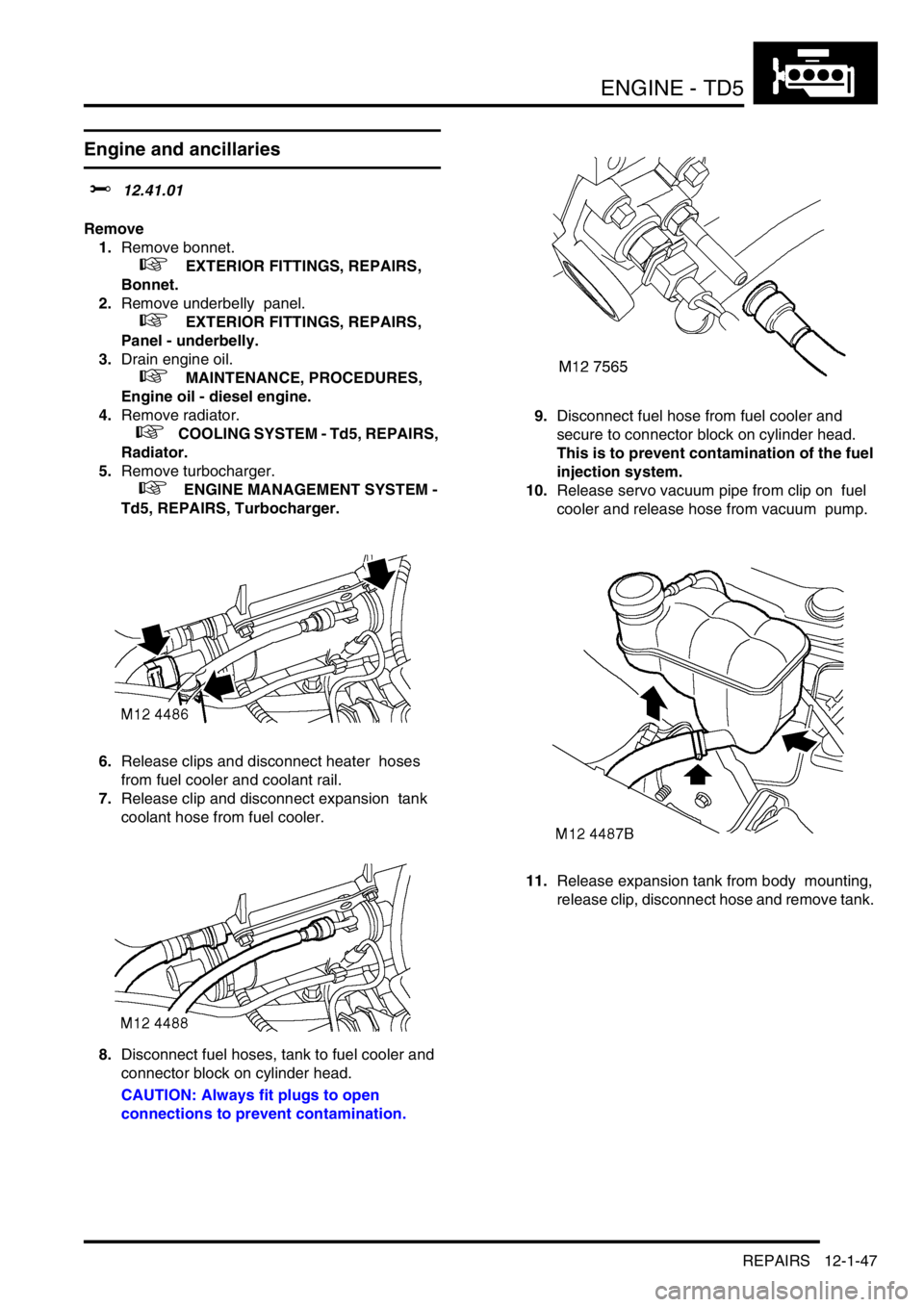
6.Release clips and disconnect heater hoses
from fuel cooler and coolant rail.
7.Release clip and disconnect expansion tank
coolant hose from fuel cooler.
8.Disconnect fuel hoses, tank to fuel cooler and
connector block on cylinder head.
CAUTION: Always fit plugs to open
connections to prevent contamination.9.Disconnect fuel hose from fuel cooler and
secure to connector block on cylinder head.
This is to prevent contamination of the fuel
injection system.
10.Release servo vacuum pipe from clip on fuel
cooler and release hose from vacuum pump.
11.Release expansion tank from body mounting,
release clip, disconnect hose and remove tank.
Page 189 of 1672
ENGINE - TD5
12-1-50 REPAIRS
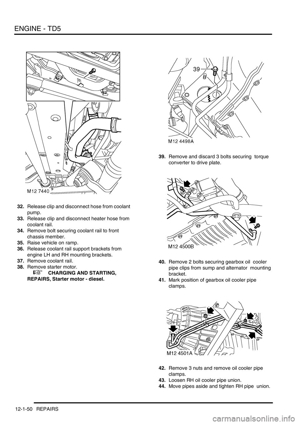
32.Release clip and disconnect hose from coolant
pump.
33.Release clip and disconnect heater hose from
coolant rail.
34.Remove bolt securing coolant rail to front
chassis member.
35.Raise vehicle on ramp.
36.Release coolant rail support brackets from
engine LH and RH mounting brackets.
37.Remove coolant rail.
38.Remove starter motor.
+ CHARGING AND STARTING,
REPAIRS, Starter motor - diesel.39.Remove and discard 3 bolts securing torque
converter to drive plate.
40.Remove 2 bolts securing gearbox oil cooler
pipe clips from sump and alternator mounting
bracket.
41.Mark position of gearbox oil cooler pipe
clamps.
42.Remove 3 nuts and remove oil cooler pipe
clamps.
43.Loosen RH oil cooler pipe union.
44.Move pipes aside and tighten RH pipe union.
Page 190 of 1672

ENGINE - TD5
REPAIRS 12-1-51
45.Remove 8 bolts and remove front cross
member.
46.Remove 6 bolts securing gearbox housing to
engine.
47.Remove 4 bolts and nuts securing RH and LH
front engine mountings to chassis.
48.Lower vehicle ramp. 49.Remove 2 upper bolts securing gearbox
housing and oil cooler coolant pipe to engine.
50.Release clip, disconnect hose from engine oil
cooler and move aside.
51.Remove bolt securing engine closing panel to
gearbox.
52.Fit tool LRT-12-138 to lifting chains and
connect to lifting eyes on engine.
53.Remove 2 nuts from RH and LH front engine
mountings.
54.Position trolley jack to support gearbox.
55.With assistance, raise chains, remove engine
from vehicle and lower onto bench.
Refit
1.With assistance, raise engine from bench and
position in vehicle.
2.With assistance, align engine to gearbox and
torque converter.
3.Position engine RH and LH mountings to
brackets and fit nuts.
4.Position engine oil cooler pipe, connect hose to
oil cooler and secure with clip.
Page 191 of 1672
ENGINE - TD5
12-1-52 REPAIRS
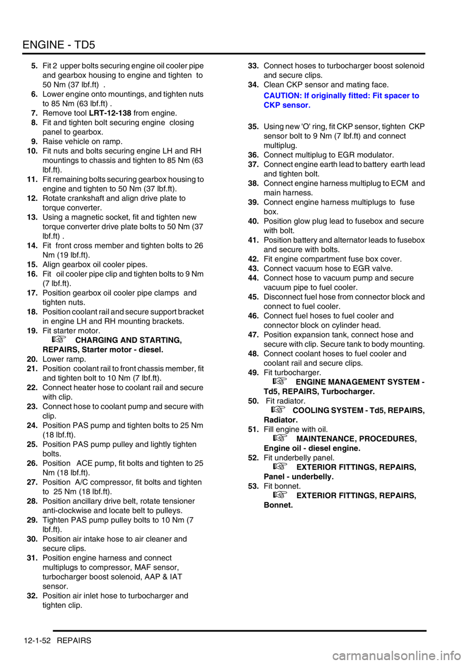
5.Fit 2 upper bolts securing engine oil cooler pipe
and gearbox housing to engine and tighten to
50 Nm (37 lbf.ft) .
6.Lower engine onto mountings, and tighten nuts
to 85 Nm (63 lbf.ft) .
7.Remove tool LRT-12-138 from engine.
8.Fit and tighten bolt securing engine closing
panel to gearbox.
9.Raise vehicle on ramp.
10.Fit nuts and bolts securing engine LH and RH
mountings to chassis and tighten to 85 Nm (63
lbf.ft).
11.Fit remaining bolts securing gearbox housing to
engine and tighten to 50 Nm (37 lbf.ft).
12.Rotate crankshaft and align drive plate to
torque converter.
13.Using a magnetic socket, fit and tighten new
torque converter drive plate bolts to 50 Nm (37
lbf.ft) .
14.Fit front cross member and tighten bolts to 26
Nm (19 lbf.ft).
15.Align gearbox oil cooler pipes.
16.Fit oil cooler pipe clip and tighten bolts to 9 Nm
(7 lbf.ft).
17.Position gearbox oil cooler pipe clamps and
tighten nuts.
18.Position coolant rail and secure support bracket
in engine LH and RH mounting brackets.
19.Fit starter motor.
+ CHARGING AND STARTING,
REPAIRS, Starter motor - diesel.
20.Lower ramp.
21.Position coolant rail to front chassis member, fit
and tighten bolt to 10 Nm (7 lbf.ft).
22.Connect heater hose to coolant rail and secure
with clip.
23.Connect hose to coolant pump and secure with
clip.
24.Position PAS pump and tighten bolts to 25 Nm
(18 lbf.ft).
25.Position PAS pump pulley and lightly tighten
bolts.
26.Position ACE pump, fit bolts and tighten to 25
Nm (18 lbf.ft).
27.Position A/C compressor, fit bolts and tighten
to 25 Nm (18 lbf.ft).
28.Position ancillary drive belt, rotate tensioner
anti-clockwise and locate belt to pulleys.
29.Tighten PAS pump pulley bolts to 10 Nm (7
lbf.ft).
30.Position air intake hose to air cleaner and
secure clips.
31.Position engine harness and connect
multiplugs to compressor, MAF sensor,
turbocharger boost solenoid, AAP & IAT
sensor.
32.Position air inlet hose to turbocharger and
tighten clip. 33.Connect hoses to turbocharger boost solenoid
and secure clips.
34.Clean CKP sensor and mating face.
CAUTION: If originally fitted: Fit spacer to
CKP sensor.
35.Using new 'O' ring, fit CKP sensor, tighten CKP
sensor bolt to 9 Nm (7 lbf.ft) and connect
multiplug.
36.Connect multiplug to EGR modulator.
37.Connect engine earth lead to battery earth lead
and tighten bolt.
38.Connect engine harness multiplug to ECM and
main harness.
39.Connect engine harness multiplugs to fuse
box.
40.Position glow plug lead to fusebox and secure
with bolt.
41.Position battery and alternator leads to fusebox
and secure with bolts.
42.Fit engine compartment fuse box cover.
43.Connect vacuum hose to EGR valve.
44.Connect hose to vacuum pump and secure
vacuum pipe to fuel cooler.
45.Disconnect fuel hose from connector block and
connect to fuel cooler.
46.Connect fuel hoses to fuel cooler and
connector block on cylinder head.
47.Position expansion tank, connect hose and
secure with clip. Secure tank to body mounting.
48.Connect coolant hoses to fuel cooler and
coolant rail and secure clips.
49.Fit turbocharger.
+ ENGINE MANAGEMENT SYSTEM -
Td5, REPAIRS, Turbocharger.
50. Fit radiator.
+ COOLING SYSTEM - Td5, REPAIRS,
Radiator.
51.Fill engine with oil.
+ MAINTENANCE, PROCEDURES,
Engine oil - diesel engine.
52.Fit underbelly panel.
+ EXTERIOR FITTINGS, REPAIRS,
Panel - underbelly.
53.Fit bonnet.
+ EXTERIOR FITTINGS, REPAIRS,
Bonnet.
Page 199 of 1672
ENGINE - TD5
12-1-60 REPAIRS
Gasket - sump
$% 12.60.38
Remove
1.Remove battery cover.
2.Disconnect battery earth lead.
3.Remove exhaust front pipe.
+ MANIFOLDS AND EXHAUST
SYSTEMS - Td5, REPAIRS, Pipe - front.
4.Drain engine oil.
5.Remove 2 bolts securing Active Cornering
Enhancement (ACE) pipes to front cross
member.
6.Remove bolt securing coolant pipe to front
cross member.
7.Remove bolt securing automatic gearbox oil
cooler pipe clip.
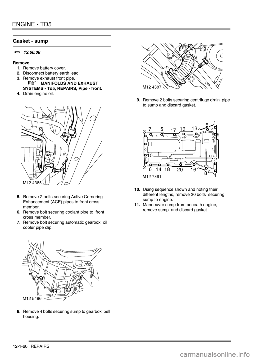
8.Remove 4 bolts securing sump to gearbox bell
housing. 9.Remove 2 bolts securing centrifuge drain pipe
to sump and discard gasket.
10.Using sequence shown and noting their
different lengths, remove 20 bolts securing
sump to engine.
11.Manoeuvre sump from beneath engine,
remove sump and discard gasket.
Page 200 of 1672

ENGINE - TD5
REPAIRS 12-1-61
Refit
1.Clean sump and mating faces.
2.Apply sealant, Part No. STC 3254 to joint faces
of timing chain cover and crankshaft rear oil
seal housing.
CAUTION: Assembly and bolt tightening
must be completed within 20 minutes of
applying sealant.
3.Position new gasket.
CAUTION: Gasket must be fitted dry.
4.Position sump and, noting the positions of the
longer bolts, fit and lightly tighten bolts.
5.Fit and lightly tighten bolts securing sump to
gearbox bell housing. 6.Working in the sequence shown, tighten bolts
securing sump to 25 Nm (18 lbf.ft).
7.Tighten – sump to gearbox bell housing bolts
to 13 Nm (10 lbf.ft).
8.Fit new gasket to centrifuge drain pipe, fit to
sump and tighten bolts to 10 Nm (7 lbf.ft ) .
CAUTION: Gasket must be fitted dry.
9.Fit bolts securing oil cooler pipe to sump and
tighten to 9 Nm (7 lbf.ft).
10.Fit and tighten bolt securing coolant pipe to
cross member.
11.Fit and tighten bolts securing ACE pipes to front
cross member.
12.Fit exhaust front pipe.
+ MANIFOLDS AND EXHAUST
SYSTEMS - Td5, REPAIRS, Pipe - front.
13.Refill engine with oil.
14.Connect battery earth lead.
15.Refit battery cover and secure fixings.