engine coolant LAND ROVER DISCOVERY 2002 Repair Manual
[x] Cancel search | Manufacturer: LAND ROVER, Model Year: 2002, Model line: DISCOVERY, Model: LAND ROVER DISCOVERY 2002Pages: 1672, PDF Size: 46.1 MB
Page 432 of 1672

ENGINE MANAGEMENT SYSTEM - TD5
DESCRIPTION AND OPERATION 18-1-39
With the ECM in a 'Secure' state, it will not function unless an alarm system is fitted to the vehicle. A 'Secure' ECM
cannot be configured into a 'No Code' ECM.
With the ECM in a 'No Code' state, it does not require an alarm system to be fitted to allow the engine to operate. If
the ECM senses that an alarm system is fitted it will not start. A 'No Code' ECM can be configured to a 'Secure' ECM
using TestBook. A 'Secure' ECM can not be configured to a 'No Code' state.
Setting up of the ECM immobilisation configurations can only be performed using TestBook.
If a vehicle stalls immediately after starting it is possible that it has been immobilised. This means either:
lThe ECM was configured as 'No Code' but the ECM is receiving a code at its alarm input pin.
lThe ECM received an incorrect code.
lThe ECM was expecting a security code but did not receive one at its alarm input pin.
Fuel delivery/injection control
The fuel delivery/injection control delivers a precise amount of finely atomised fuel to mix with the air in the
combustion chamber to create a controlled explosion.
To precisely control fuel delivery and control fuel injection, the following input conditions must be met:
lCKP information.
lInjection timing map information.
lFT information.
lECT information.
The ECM monitors the conditions required for optimum combustion of fuel in the cylinder from the various sensors
around the engine and then compares it against stored information. From this calculation the ECM can adjust the
quantity and timing of the fuel being delivered to the cylinder.
The ECM uses CKP information as follows:
lTo calculate engine speed.
lTo determine engine crankshaft position.
Engine speed and crankshaft position allows the ECM to determine fuel injection timing.
The ECM also uses ECT information and FT sensor information to allow optimum fuel delivery and injection control
for all engine coolant and fuel temperatures.
Turbocharger control
Turbocharger control is vital to ensure the turbocharger does not over boost the engine. Within the turbocharger is a
wastegate, which when operated by the turbocharger wastegate modulator will open and close a bypass valve
regulating boost pressure.
The turbocharger wastegate modulator, via the ECM, controls boost pressure under the following conditions:
lAcceleration.
lWide open throttle.
lIdle.
lOverrun.
The turbocharger wastegate modulator receives a battery voltage supply from the main relay. The ECM supplies the
earth path in the form of a pulse width modulation (PWM) signal. This signal allows the turbocharger wastegate
modulator to open and close the wastegate. A proportion of the exhaust gas can bypass the turbocharger through
the wastegate, regulating boost pressure.
Page 440 of 1672
ENGINE MANAGEMENT SYSTEM - TD5
REPAIRS 18-1-47
REPAIRS
Engine control module (ECM)
$% 18.30.03
All replacement ECM's are configured for two track
TP sensors. When fitting replacement ECM to
vehicle with three track TP sensor, TestBook must be
used to configure ECM for three track TP sensor.
Remove
1.Release fixings and remove battery cover.
2.Disconnect battery earth lead.
3.Release retaining strap and remove vehicle
jack.
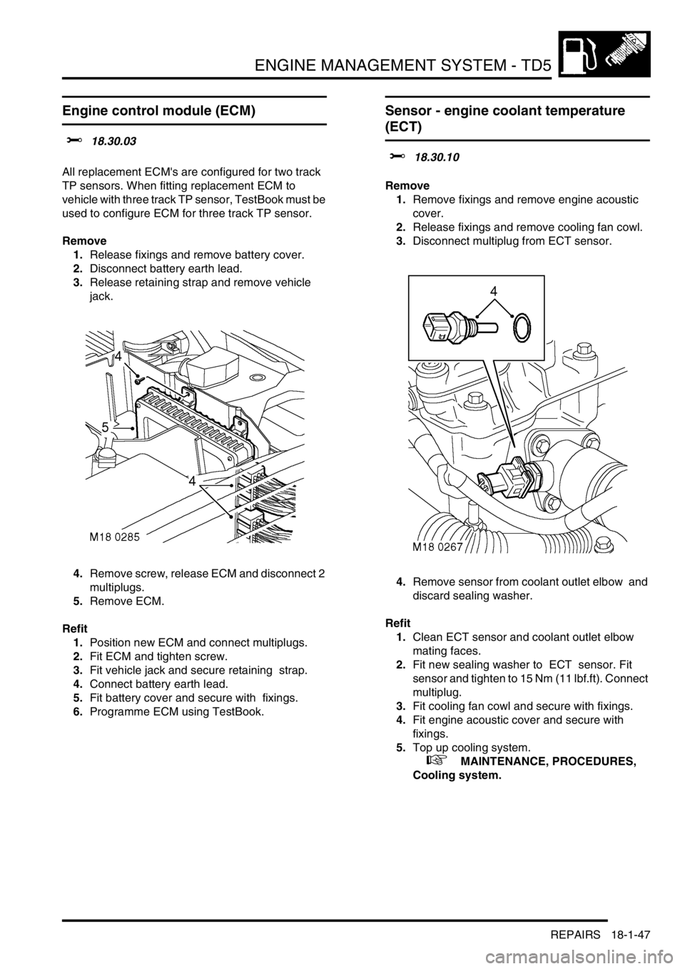
4.Remove screw, release ECM and disconnect 2
multiplugs.
5.Remove ECM.
Refit
1.Position new ECM and connect multiplugs.
2.Fit ECM and tighten screw.
3.Fit vehicle jack and secure retaining strap.
4.Connect battery earth lead.
5.Fit battery cover and secure with fixings.
6.Programme ECM using TestBook.
Sensor - engine coolant temperature
(ECT)
$% 18.30.10
Remove
1.Remove fixings and remove engine acoustic
cover.
2.Release fixings and remove cooling fan cowl.
3.Disconnect multiplug from ECT sensor.
4.Remove sensor from coolant outlet elbow and
discard sealing washer.
Refit
1.Clean ECT sensor and coolant outlet elbow
mating faces.
2.Fit new sealing washer to ECT sensor. Fit
sensor and tighten to 15 Nm (11 lbf.ft). Connect
multiplug.
3.Fit cooling fan cowl and secure with fixings.
4.Fit engine acoustic cover and secure with
fixings.
5.Top up cooling system.
+ MAINTENANCE, PROCEDURES,
Cooling system.
Page 446 of 1672
ENGINE MANAGEMENT SYSTEM - TD5
REPAIRS 18-1-53
Element - fuel filter
$% 19.25.07
Remove
1.Release turnbuckles and remove battery cover.
2.Disconnect battery earth lead.
3.Raise rear of vehicle.
WARNING: Do not work on or under a
vehicle supported only by a jack. Always
support the vehicle on safety stands.
4.Clean area around fuel filter.
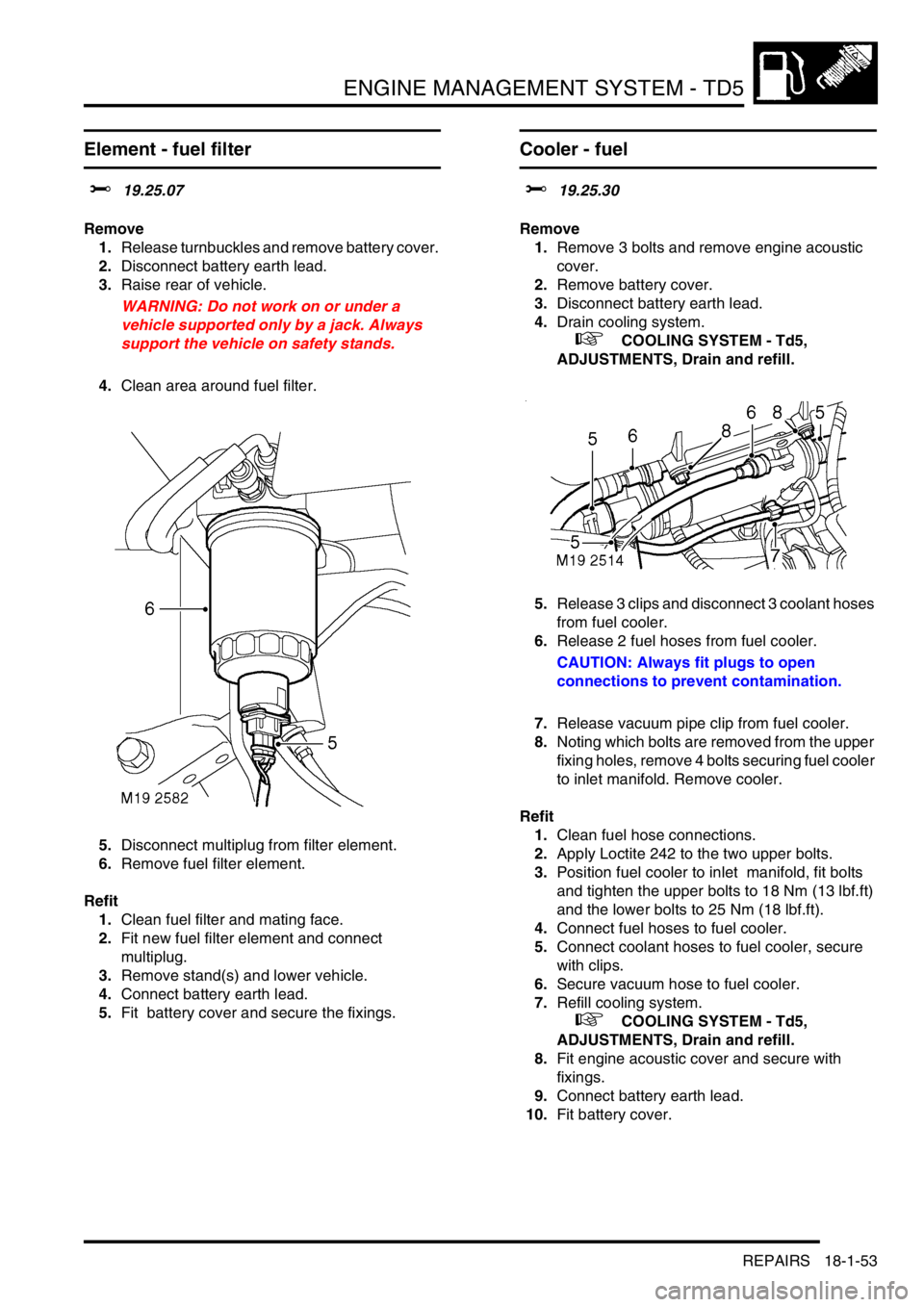
5.Disconnect multiplug from filter element.
6.Remove fuel filter element.
Refit
1.Clean fuel filter and mating face.
2.Fit new fuel filter element and connect
multiplug.
3.Remove stand(s) and lower vehicle.
4.Connect battery earth lead.
5.Fit battery cover and secure the fixings.
Cooler - fuel
$% 19.25.30
Remove
1.Remove 3 bolts and remove engine acoustic
cover.
2.Remove battery cover.
3.Disconnect battery earth lead.
4.Drain cooling system.
+ COOLING SYSTEM - Td5,
ADJUSTMENTS, Drain and refill.
5.Release 3 clips and disconnect 3 coolant hoses
from fuel cooler.
6.Release 2 fuel hoses from fuel cooler.
CAUTION: Always fit plugs to open
connections to prevent contamination.
7.Release vacuum pipe clip from fuel cooler.
8.Noting which bolts are removed from the upper
fixing holes, remove 4 bolts securing fuel cooler
to inlet manifold. Remove cooler.
Refit
1.Clean fuel hose connections.
2.Apply Loctite 242 to the two upper bolts.
3.Position fuel cooler to inlet manifold, fit bolts
and tighten the upper bolts to 18 Nm (13 lbf.ft)
and the lower bolts to 25 Nm (18 lbf.ft).
4.Connect fuel hoses to fuel cooler.
5.Connect coolant hoses to fuel cooler, secure
with clips.
6.Secure vacuum hose to fuel cooler.
7.Refill cooling system.
+ COOLING SYSTEM - Td5,
ADJUSTMENTS, Drain and refill.
8.Fit engine acoustic cover and secure with
fixings.
9.Connect battery earth lead.
10.Fit battery cover.
Page 460 of 1672
ENGINE MANAGEMENT SYSTEM - V8
DESCRIPTION AND OPERATION 18-2-3
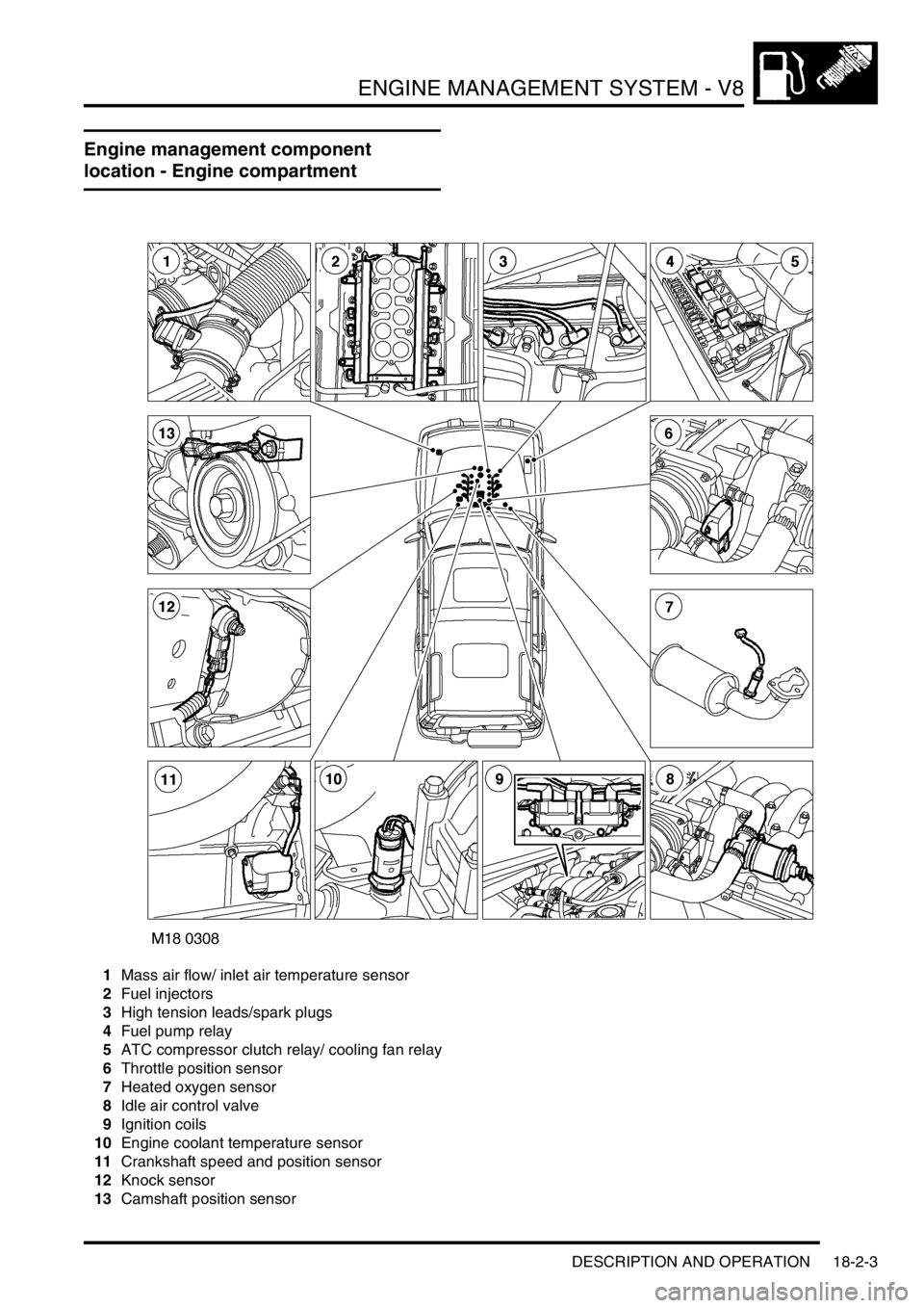
Engine management component
location - Engine compartment
1Mass air flow/ inlet air temperature sensor
2Fuel injectors
3High tension leads/spark plugs
4Fuel pump relay
5ATC compressor clutch relay/ cooling fan relay
6Throttle position sensor
7Heated oxygen sensor
8Idle air control valve
9Ignition coils
10Engine coolant temperature sensor
11Crankshaft speed and position sensor
12Knock sensor
13Camshaft position sensor
Page 462 of 1672

ENGINE MANAGEMENT SYSTEM - V8
DESCRIPTION AND OPERATION 18-2-5
1Engine control module
2Crankshaft speed and position sensor
3Camshaft position sensor
4Engine coolant temperature sensor
5Mass air flow/ inlet air temperature sensor
6Throttle position sensor
7Heated oxygen sensors
8Fuel injectors
9Idle air control valve
10Fuel pump relay
11EVAP canister
12EVAP canister vent valve
13EVAP canister purge valve
14Fuel tank pressure sensor
15Ignition coils
16Knock sensor
17Spark plugs
18High/ Low ratio switch
19Malfunction indication lamp
20Diagnostic connector
21Air temperature control clutch relay
22Air temperature control cooling fan relay
23ATC ECU
24CAN link to EAT
25SLABS ECU
26BCU
27Instrument cluster
28Thermostat monitoring sensor (where fitted)
Page 463 of 1672

ENGINE MANAGEMENT SYSTEM - V8
18-2-6 DESCRIPTION AND OPERATION
Description - engine management
General
The V8 engine is equipped with the Bosch Motronic M5.2.1 engine management system. This system is a sequential
multiport fuel injection system controlled by an Engine Control Module (ECM).
A single ECM is used for the control of the existing 4.0 litre engine and the new 4.6 litre engine introduced with 03
model year vehicles for the NAS market only. The ECM contains the tunes for both engines variants. When the ECM
is replaced, TestBook/T4 must be used to select the correct tune to match the engine fitment.
The ECM has On Board Diagnostic (OBD) strategies as required by various market legislative bodies. To meet these
requirements the system monitors and reports on any faults that cause excessive exhaust emissions.
In markets that mandate OBD, the ECM monitors performance of the engine for misfires, catalyst efficiency, exhaust
leaks and evaporative control loss. If a fault occurs, the ECM stores the relevant fault code and warns the driver of
component failure by illuminating the Malfunction Indicator Light in the instrument pack.
In markets where OBD is not mandatory, the ECM will still monitor performance of the engine and store the fault code,
but will not illuminate the Malfunction Indicator Light.
The ECM uses input and output information from its sensors and actuators to control the following engine conditions:
lFuel quantity.
lClosed loop fuelling.
lOpen loop fuelling.
lIgnition timing.
lKnock control.
lIdle speed control.
lEmission control.
lOn-Board Diagnostic (OBD) where applicable.
lVehicle immobilisation.
lMisfire detection (where applicable).
lVehicle speed signal.
lRough road signal (where applicable).
lLow fuel level signal (where applicable).
lCoolant temperature gauge signal.
The ECM processes sensor information from the following input sources:
lIgnition switch (position II).
lCrankshaft speed and position sensor.
lCamshaft position sensor.
lEngine coolant temperature sensor.
lMass air flow sensor.
lIntake air temperature sensor.
lKnock sensor.
lThrottle position sensor.
lHeated oxygen sensors.
lHigh/ Low ratio switch.
lFuel tank pressure sensor (where fitted)
lThermostat monitoring sensor (where fitted)
Page 466 of 1672

ENGINE MANAGEMENT SYSTEM - V8
DESCRIPTION AND OPERATION 18-2-9
Connector 3 (C0636): This connector contains 52 pins and is used for most sensor and actuator inputs and outputs.
Sensor and actuator control is vital to ensure that the ECM maintains adaptive strategy
Pin out details connector C0636
Pin No. Function Signal type Reading
1 Injector cylinder number 2 Output Switch to earth
2 Injector cylinder number 5 Output Switch to earth
3 Purge valve Output, signal PWM 12-0V
4 SAI vacuum solenoid valve (NAS vehicles from
2000MY only)Output Switch to earth
5 Not used - -
6 Fuel tank pressure sensor (NAS vehicles with
vacuum type, EVAP system leak detection
only)Earth 0V
7 MAF sensor 5V supply Output, reference 5V
8 Not used - -
9 MAF sensor earth Earth 0V
10 TP sensor 5V supply Output, reference 5V
11 Not used - -
12 Not used - -
13 Not used - -
14 Injector cylinder number 7 Output Switch to earth
15 Injector cylinder number 6 Output Switch to earth
16 SAI pump relay (NAS vehicles from 2000MY
only)Output Switch to earth
17 CMP sensor Earth 0V
18 Low range switch (manual transmission only) Input, signal Active low
19 Not used - -
20 CMP signal Input, signal Digital switch 0-12V
21 ECT sensor Earth 0V
22 Coolant temperature signal Input, signal Analogue 0-5V
23 MAF sensor signal Input, signal Analogue 0-5V
24 TP sensor signal Input, signal Analogue 0-5V
25 TP sensor earth Earth 0V
26 Not used - -
27 Injector cylinder number 3 Output Switch to earth
28 Injector cylinder number 8 Output Switch to earth
29 Hill decent control output Output, signal PWM 0-12V
30 EVAP canister vent solenoid (CVS) valve (NAS
vehicles with vacuum type, EVAP system leak
detection only)Output Switch to earth
30 Leak detection pump solenoid (NAS vehicles
with positive pressure type, EVAP system leak
detection only)Output Switch to earth
31 A/C condenser fan Output Switch to earth
32 CKP sensor signal Input, signal Analogue, 0-300V peak
33 Not used - -
34 IAT sensor signal Input, signal Analogue 0-5V
35 KS, RH bank earth Earth 0V
36 KS, RH bank signal Input, signal Analogue
37 Not used - -
38 Not used - -
39 Not used - -
40 Injector cylinder number 4 Output Switch to earth
41 Injector cylinder number 1 Output Switch to earth
Page 472 of 1672
ENGINE MANAGEMENT SYSTEM - V8
DESCRIPTION AND OPERATION 18-2-15
Input/Output
Electrical input to the camshaft position sensor is from fuse 2 located in engine compartment fuse box. One output is
sensor earth, the other is the signal output to the ECM via pin 20 of connector C0636.
The CMP sensor can fail the following ways or supply incorrect signal:
lSensor open circuit.
lShort circuit to vehicle battery supply.
lShort circuit to vehicle earth.
lIncorrect fitting of the sensor.
lExcessive camshaft gear wheel tolerance.
lExcessive camshaft endfloat.
lCamshaft and crankshaft misalignment.
lSpeed signal correlation with CKP sensor signal.
lCam wheel magnetised / residual magnetism
In the event of a CMP sensor signal failure any of the following symptoms may be observed:
lIgnition timing reverts to default values from ECM memory.
lLoss of cylinder correction.
lLoss of active knock control.
lLoss of active knock control diagnostics.
lLoss of cylinder identification for misfire diagnostics.
lLoss of quick synchronisation of crankshaft and camshaft for cranking/ start up.
lFuel injection could be 360
° out of phase.
lFront HO
2S sensor ageing period diagnostic disabled (NAS only)
Should a malfunction of the component occur the following fault code may be evident and can be retrieved by
TestBook:
The fault condition has to be detected for more than 100 cam pulses (25 revolutions) when the engine speed is greater
than 500 rev/min.
Engine Coolant Temperature (ECT) sensor (C0196)
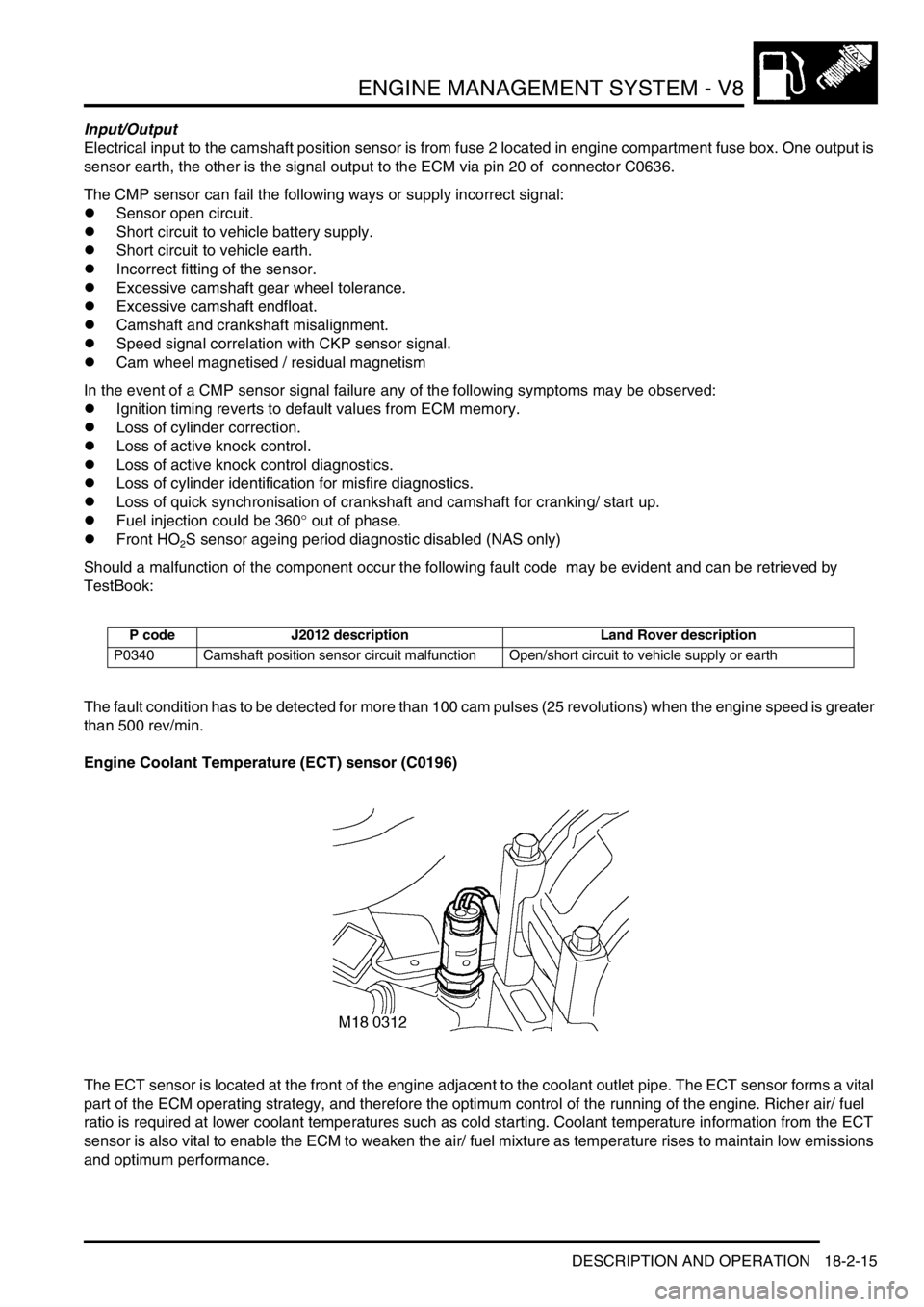
The ECT sensor is located at the front of the engine adjacent to the coolant outlet pipe. The ECT sensor forms a vital
part of the ECM operating strategy, and therefore the optimum control of the running of the engine. Richer air/ fuel
ratio is required at lower coolant temperatures such as cold starting. Coolant temperature information from the ECT
sensor is also vital to enable the ECM to weaken the air/ fuel mixture as temperature rises to maintain low emissions
and optimum performance.
P code J2012 description Land Rover description
P0340 Camshaft position sensor circuit malfunction Open/short circuit to vehicle supply or earth
Page 473 of 1672
ENGINE MANAGEMENT SYSTEM - V8
18-2-16 DESCRIPTION AND OPERATION
For NAS vehicles with secondary air injection, the signal from the ECT sensor is monitored at engine start, to
determine whether the conditions are cold enough to warrant secondary air injection to be employed. The ECT sensor
is then monitored to switch off the secondary air injection when the required engine coolant temperature has been
attained.
+ EMISSION CONTROL - V8, DESCRIPTION AND OPERATION, Secondary air injection system.
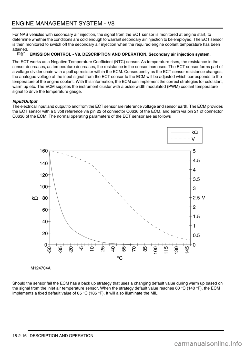
The ECT works as a Negative Temperature Coefficient (NTC) sensor. As temperature rises, the resistance in the
sensor decreases, as temperature decreases, the resistance in the sensor increases. The ECT sensor forms part of
a voltage divider chain with a pull up resistor within the ECM. Consequently as the ECT sensor resistance changes,
the analogue voltage at the input signal from the ECT sensor to the ECM will be adjusted which corresponds to the
temperature of the engine coolant. With this information, the ECM can implement the correct strategies for cold start,
warm up etc. The ECM supplies the instrument cluster with a pulse width modulated (PWM) coolant temperature
signal to drive the temperature gauge.
Input/Output
The electrical input and output to and from the ECT sensor are reference voltage and sensor earth. The ECM provides
the ECT sensor with a 5 volt reference via pin 22 of connector C0636 of the ECM, and earth via pin 21 of connector
C0636 of the ECM. The normal operating parameters of the ECT sensor are as follows
Should the sensor fail the ECM has a back up strategy that uses a changing default value during warm up based on
the signal from the inlet air temperature sensor. When the strategy default value reaches 60
°C (140 °F), the ECM
implements a fixed default value of 85
°C (185 °F). It will also illuminate the MIL.
M124704A
0
20
40
60
80
100
120
140
160
0
0.5
1
1.5
2
2.5
3
3.5
4
4.5
5
VkΩ
kΩ
V
°C
145-50-35-20-5102540557085100115130
Page 474 of 1672

ENGINE MANAGEMENT SYSTEM - V8
DESCRIPTION AND OPERATION 18-2-17
The ECT sensor can fail the following ways or supply incorrect signal:
lSensor open circuit.
lShort circuit to vehicle supply.
lShort circuit to earth.
lIncorrect mechanical fitting.
lSignal fixed above 40
°C (140 °F) will not be detected.
lSignal fixed below 40
°C (140 °F) will be detected.
In the event of an ECT sensor signal failure any of the following symptoms may be observed:
lDifficult cold start.
lDifficult hot start.
lDriveability concern.
lMIL illuminated.
lInstrument cluster temperature warning lamp illuminated.
lTemperature gauge reads excessively hot.
lTemperature gauge reads excessively cold.
lCooling fan will not run.
There are three types of ECT sensor diagnostic checks:
lThe ECT sensor signal is within limits, but is inaccurate – the engine has to be running and the signal indicates
a coolant temperature below 40
°C (104°F). The signal differs too much from the coolant temperature model for
longer than 2.53 seconds.
lThe ECT sensor signal is greater than the maximum threshold value – the ECM has to be powered up to perform
the diagnostic, but the engine does not need to be running.
lThe ECT sensor signal is less than the minimum threshold value – the ECM has to be powered up to perform
the diagnostic, but the engine does not need to be running.
Should a malfunction of the component occur the following fault codes may be evident and can be retrieved by
TestBook:
P code J2012 description Land Rover description
P0116 Engine coolant temperature circuit/range
performance problemSignal differs too much from temperature model for
longer than 2.53s
P0117 Engine coolant temperature circuit low input Open circuit or short circuit to battery supply
P0118 Engine coolant temperature circuit high input Short circuit to earth