engine coolant LAND ROVER DISCOVERY 2002 Repair Manual
[x] Cancel search | Manufacturer: LAND ROVER, Model Year: 2002, Model line: DISCOVERY, Model: LAND ROVER DISCOVERY 2002Pages: 1672, PDF Size: 46.1 MB
Page 375 of 1672

EMISSION CONTROL - V8
17-2-38 DESCRIPTION AND OPERATION
Evaporative emission control operation
Fuel vapour is stored in the activated charcoal (EVAP) canister for retention when the vehicle is not operating. When
the vehicle is operating, fuel vapour is drawn from the canister into the engine via a purge control valve. The vapour
is then delivered to the intake plenum chamber to be supplied to the engine cylinders where it is burned in the
combustion process.
During fuel filling the fuel vapour displaced from the fuel tank is allowed to escape to atmosphere, valves within the
fuel filler prevent any vapour escaping through to the EVAP canister as this can adversely affect the fuel cut-off height.
Only fuel vapour generated whilst driving is prevented from escaping to atmosphere by absorption into the charcoal
canister. The fuel filler shuts off to leave the tank approximately 10% empty to ensure the ROVs are always above
the fuel level and so vapour can escape to the EVAP canister and the tank can breathe. The back pressures normally
generated during fuel filling are too low to open the pressure relief valve, but vapour pressures accumulated during
driving are higher and can open the pressure relief valve. Should the vehicle be overturned, the ROVs shut off to
prevent any fuel spillage.
Fuel vapour generated from within the fuel tank as the fuel heats up is stored in the tank until the pressure exceeds
the operating pressure of the two-way valve. When the two-way valve opens, the fuel vapour passes along the vent
line from the fuel tank (via the fuel tank vapour separator) to the evaporation inlet port of the EVAP canister. The fuel
tank vents between 5.17 and 6.9 kPa.
Fuel vapour evaporating from the fuel tank is routed to the EVAP canister through the fuel vapour separator and vent
line. Liquid fuel must not be allowed to contaminate the charcoal in the EVAP canister. To prevent this, the fuel vapour
separator fitted to the fuel neck allows fuel to drain back into the tank. As the fuel vapour cools, it condenses and is
allowed to flow back into the fuel tank from the vent line by way of the two-way valve.
The EVAP canister contains charcoal which absorbs and stores fuel vapour from the fuel tank while the engine is not
running. When the canister is not being purged, the fuel vapour remains in the canister and clean air exits the canister
via the air inlet port.
The engine management ECM controls the electrical output signal to the purge valve. The system will not work
properly if there is leakage or clogging within the system or if the purge valve cannot be controlled.
+ ENGINE MANAGEMENT SYSTEM - V8, DESCRIPTION AND OPERATION, Description - engine
management.
When the engine is running, the ECM decides when conditions are correct for vapour to be purged from the EVAP
canister and opens the canister purge valve. This connects a manifold vacuum line to the canister and fuel vapour
containing the hydrocarbons is drawn from the canister's charcoal element to be burned in the engine. Clean air is
drawn into the canister through the atmosphere vent port to fill the displaced volume of vapour.
The purge valve remains closed below preset coolant and engine speed values to protect the engine tune and
catalytic converter performance. If the EVAP canister was purged during cold running or at idling speed, the additional
enrichment in the fuel mixture would delay the catalytic converter light off time and cause erratic idle. When the purge
valve is opened, fuel vapour from the EVAP canister is drawn into the plenum chamber downside of the throttle
housing, to be delivered to the combustion chambers for burning.
The purge valve is opened and closed in accordance with a pulse width modulated (PWM) signal supplied from the
engine management ECM. The system will not work properly if the purge valve cannot be controlled. Possible failure
modes associated with the purge valve are listed below:
lValve drive open circuit.
lShort circuit to vehicle supply or ground.
lPurge valve or pipework blocked or restricted.
lPurge valve stuck open.
lPipework joints leaking or disconnected.
Page 379 of 1672

EMISSION CONTROL - V8
17-2-42 DESCRIPTION AND OPERATION
Secondary air injection system
When the engine is started, the engine control module checks the engine coolant temperature and if it is below 55°
C, the ECM grounds the electrical connection to the coil of the secondary air injection (SAI) pump relay.
A 12V battery supply is fed to the inertia switch via fuse 13 in the engine compartment fusebox. When the inertia
switch contacts are closed, the feed passes through the switch and is connected to the coil of the Main relay. An earth
connection from the Main relay coil is connected to the ECM. When the ECM completes the earth path, the coil
energises and closes the contacts of the Main relay.
The Main and Secondary Air Injection (SAI) pump relays are located in the engine compartment fusebox. When the
contacts of the Main relay are closed, a 12V battery supply is fed to the coil of the SAI pump relay. An earth connection
from the coil of the SAI pump relay is connected to the ECM. When the ECM completes the earth path, the coil
energises and closes the contacts of the SAI pump relay to supply 12V to the SAI pump via fusible link 2 in the engine
compartment fusebox. The SAI pump starts to operate, and will continue to do so until the ECM switches off the earth
connection to the coil of the SAI pump relay.
The SAI pump remains operational for a period determined by the ECM and depends on the starting temperature of
the engine, or for a maximum operation period determined by the ECM if the target engine coolant temperature has
not been reached in the usual time.
When the contacts of the main relay are closed, a 12V battery supply is fed to the SAI solenoid valve via Fuse 2 in
the engine compartment fusebox.
The ECM grounds the electrical connection to the SAI vacuum solenoid valve at the same time as it switches on the
SAI pump motor. When the SAI vacuum solenoid valve is energised, a vacuum is provided to the operation control
ports on both of the vacuum operated SAI control valves at the exhaust manifolds. The control vacuum is sourced
from the intake manifold depression and routed to the SAI control valves via a vacuum reservoir and the SAI vacuum
solenoid valve.
The vacuum reservoir is included in the vacuum supply circuit to prevent vacuum fluctuations caused by changes in
the intake manifold depression affecting the operation of the SAI control valves.
When a vacuum is applied to the control ports of the SAI control valves, the valves open to allow pressurised air from
the SAI pump to pass through to the exhaust ports in the cylinder heads for combustion.
When the ECM has determined that the SAI pump has operated for the desired duration, it switches off the earth paths
to the SAI pump relay and the SAI vacuum solenoid valve. With the SAI vacuum solenoid valve de-energised, the
valve closes, cutting off the vacuum supply to the SAI control valves. The SAI control valves close immediately and
completely to prevent any further pressurised air from the SAI pump entering the exhaust manifolds.
The engine coolant temperature sensor incurs a time lag in respect of detecting a change in temperature and the SAI
pump automatically enters a 'soak period' between operations to prevent the SAI pump overheating. The ECM also
compares the switch off and start up temperatures, to determine whether it is necessary to operate the SAI pump.
This prevents the pump running repeatedly and overheating on repeat starts.
Other factors which may prevent or stop SAI pump operation include the prevailing engine speed / load conditions.
Page 390 of 1672

EMISSION CONTROL - V8
REPAIRS 17-2-53
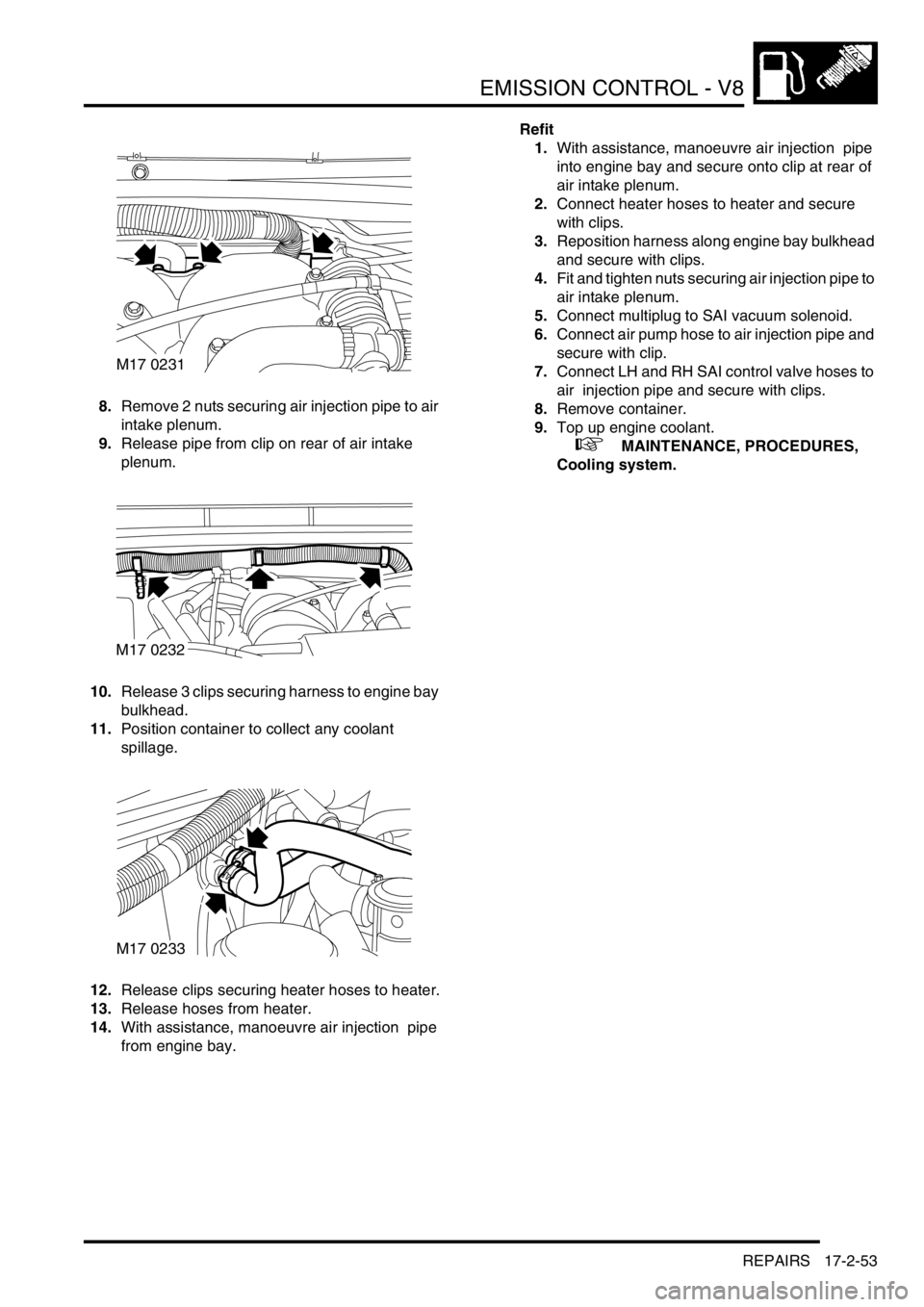
8.Remove 2 nuts securing air injection pipe to air
intake plenum.
9.Release pipe from clip on rear of air intake
plenum.
10.Release 3 clips securing harness to engine bay
bulkhead.
11.Position container to collect any coolant
spillage.
12.Release clips securing heater hoses to heater.
13.Release hoses from heater.
14.With assistance, manoeuvre air injection pipe
from engine bay.Refit
1.With assistance, manoeuvre air injection pipe
into engine bay and secure onto clip at rear of
air intake plenum.
2.Connect heater hoses to heater and secure
with clips.
3.Reposition harness along engine bay bulkhead
and secure with clips.
4.Fit and tighten nuts securing air injection pipe to
air intake plenum.
5.Connect multiplug to SAI vacuum solenoid.
6.Connect air pump hose to air injection pipe and
secure with clip.
7.Connect LH and RH SAI control valve hoses to
air injection pipe and secure with clips.
8.Remove container.
9.Top up engine coolant.
+ MAINTENANCE, PROCEDURES,
Cooling system.
M17 0231
M17 0232
M17 0233
Page 396 of 1672

ENGINE MANAGEMENT SYSTEM - TD5
DESCRIPTION AND OPERATION 18-1-3
Engine management component
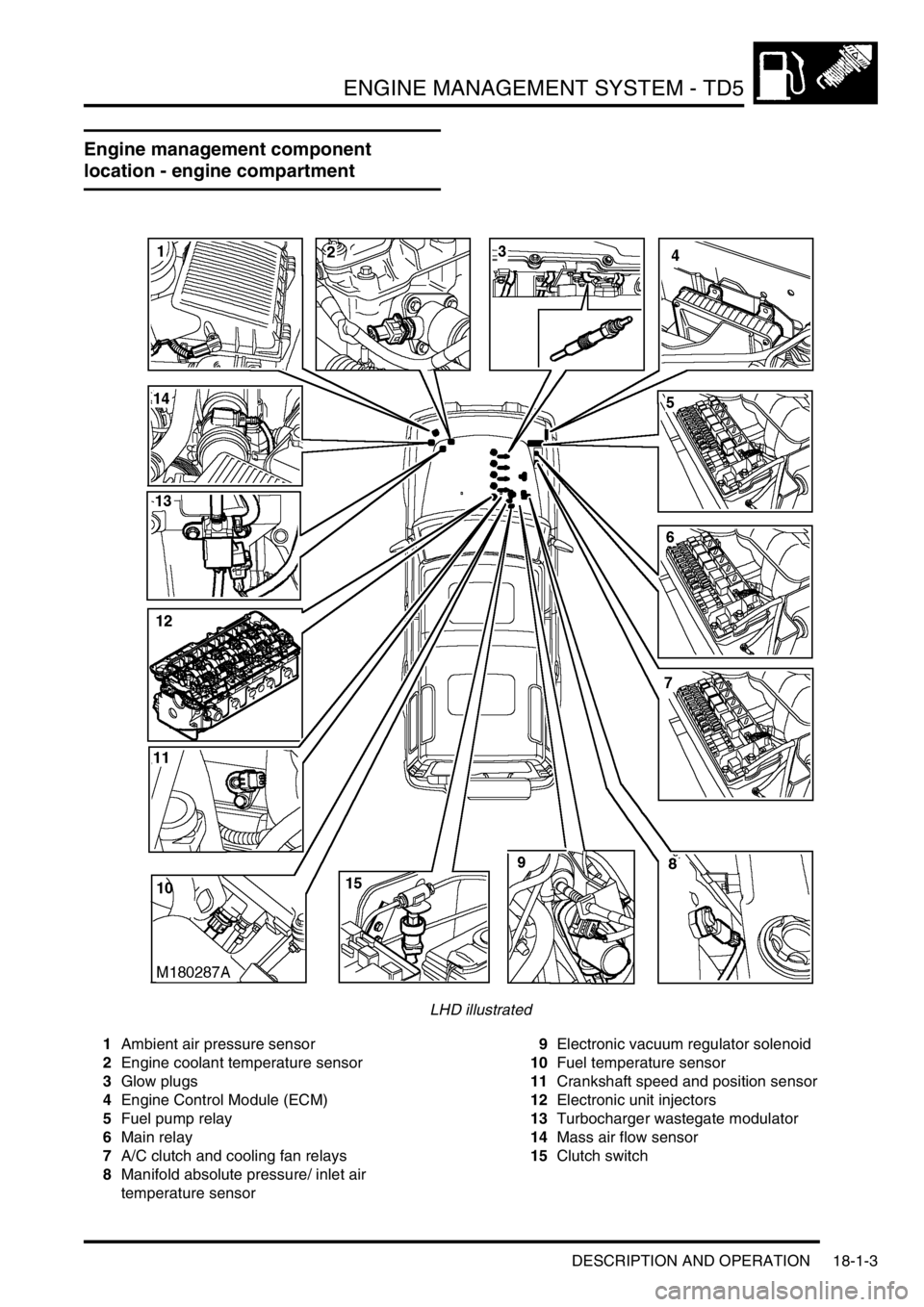
location - engine compartment
LHD illustrated
1Ambient air pressure sensor
2Engine coolant temperature sensor
3Glow plugs
4Engine Control Module (ECM)
5Fuel pump relay
6Main relay
7A/C clutch and cooling fan relays
8Manifold absolute pressure/ inlet air
temperature sensor9Electronic vacuum regulator solenoid
10Fuel temperature sensor
11Crankshaft speed and position sensor
12Electronic unit injectors
13Turbocharger wastegate modulator
14Mass air flow sensor
15Clutch switch
Page 398 of 1672

ENGINE MANAGEMENT SYSTEM - TD5
DESCRIPTION AND OPERATION 18-1-5
1Mass air flow sensor
2Ambient air pressure sensor
3Manifold absolute pressure/ inlet air
temperature sensor
4Engine coolant temperature sensor
5Crankshaft speed and position sensor
6Throttle position sensor
7Fuel temperature sensor
8Brake pedal switch
9Clutch switch
10High/ Low ratio switch
11Main relay
12Malfunction indicator lamp
13Fuel pump relay
14Glow plug warning lamp
15Glow plugs16Electronic unit injectors
17Turbocharger wastegate modulator
18EGR modulator
19Diagnostic connector
20Engine control module
21Cruise control master switch
22Cruise control SET+ switch
23Cruise control RES switch
24Air conditioning clutch relay
25Air conditioning cooling fan relay
26Electronic automatic transmission ECU
27Self levelling and anti-lock brakes ECU
28Instrument cluster
29Body control unit
Page 399 of 1672

ENGINE MANAGEMENT SYSTEM - TD5
18-1-6 DESCRIPTION AND OPERATION
Description
General
An engine control module (ECM) controls the five-cylinder direct injection diesel engine, and works on the drive by
wire principle. This means there is no throttle cable, the ECM controls the drivers needs via a signal from the Throttle
Position (TP) sensor on the throttle pedal.
The ECM is a full authoritative diesel specific microprocessor that also incorporates features for cruise control and air
conditioning control. In addition, the ECM supplies output control for the exhaust gas recirculation and turbocharger
boost pressure. The ECM has a self-diagnostic function, which is able to provide backup strategies for most sensor
failures.
The ECM processes information from the following input sources:
lMass air flow sensor.
lAmbient air pressure sensor.
lManifold absolute pressure/inlet air temperature sensor.
lEngine coolant temperature sensor.
lCrankshaft speed and position sensor.
lThrottle position sensor.
lFuel temperature sensor.
lAir conditioning request.
lAir conditioning fan request.
lBrake pedal switch.
lClutch switch.
lCruise control master switch.
lCruise control SET+ switch.
lCruise control RES switch.
lHigh/low ratio switch.
The input from the sensors constantly updates the ECM with the current operating condition of the engine. Once the
ECM has compared current information with stored information within its memory, it can make any adjustment it
requires to the operation of the engine via the following:
lAir conditioning clutch relay.
lAir conditioning cooling fan relay.
lElectronic vacuum regulator solenoid.
lMalfunction indicator lamp.
lFuel pump relay.
lGlow plug warning lamp.
lGlow plugs.
lFuel injectors.
lMain relay.
lTurbocharger wastegate modulator.
lTemperature gauge.
The ECM interfaces with the following:
lElectronic Automatic Transmission (EAT).
lSelf Levelling and Anti-lock Brakes System (SLABS).
lSerial communication link.
lInstrument cluster.
lBody Control Unit (BCU).
Page 400 of 1672

ENGINE MANAGEMENT SYSTEM - TD5
DESCRIPTION AND OPERATION 18-1-7
Engine Control Module (ECM)
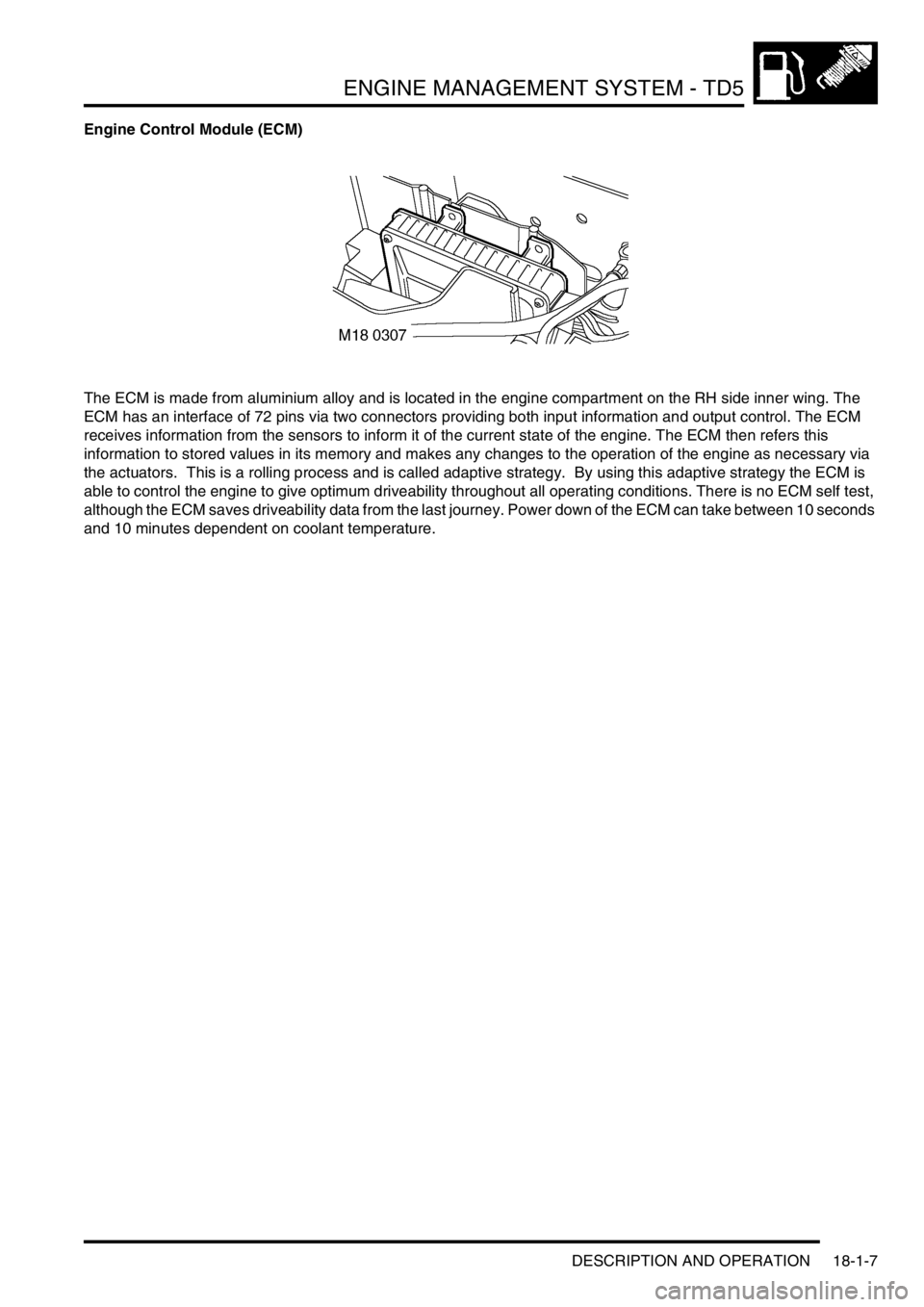
The ECM is made from aluminium alloy and is located in the engine compartment on the RH side inner wing. The
ECM has an interface of 72 pins via two connectors providing both input information and output control. The ECM
receives information from the sensors to inform it of the current state of the engine. The ECM then refers this
information to stored values in its memory and makes any changes to the operation of the engine as necessary via
the actuators. This is a rolling process and is called adaptive strategy. By using this adaptive strategy the ECM is
able to control the engine to give optimum driveability throughout all operating conditions. There is no ECM self test,
although the ECM saves driveability data from the last journey. Power down of the ECM can take between 10 seconds
and 10 minutes dependent on coolant temperature.
Page 407 of 1672

ENGINE MANAGEMENT SYSTEM - TD5
18-1-14 DESCRIPTION AND OPERATION
Engine Coolant Temperature (ECT) sensor
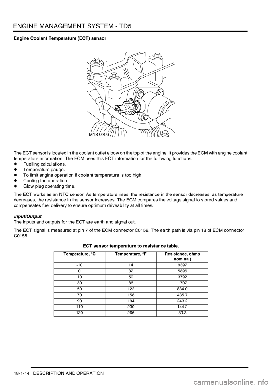
The ECT sensor is located in the coolant outlet elbow on the top of the engine. It provides the ECM with engine coolant
temperature information. The ECM uses this ECT information for the following functions:
lFuelling calculations.
lTemperature gauge.
lTo limit engine operation if coolant temperature is too high.
lCooling fan operation.
lGlow plug operating time.
The ECT works as an NTC sensor. As temperature rises, the resistance in the sensor decreases, as temperature
decreases, the resistance in the sensor increases. The ECM compares the voltage signal to stored values and
compensates fuel delivery to ensure optimum driveability at all times.
Input/Output
The inputs and outputs for the ECT are earth and signal out.
The ECT signal is measured at pin 7 of the ECM connector C0158. The earth path is via pin 18 of ECM connector
C0158.
ECT sensor temperature to resistance table.
Temperature, °C Temperature, °F Resistance, ohms
nominal)
-10 14 9397
0325896
10 50 3792
30 86 1707
50 122 834.0
70 158 435.7
90 194 243.2
110 230 144.2
130 266 89.3
Page 408 of 1672

ENGINE MANAGEMENT SYSTEM - TD5
DESCRIPTION AND OPERATION 18-1-15
The ECT sensor can fail the following ways or supply incorrect signal:
lSensor open circuit.
lShort circuit to vehicle supply.
lShort circuit to earth.
lIncorrect mechanical fitting.
lSignal fixed above 40
°C (104 °F) not detected.
lSignal fixed below 40
°C (104 °F) not detected.
In the event of an ECT sensor signal failure any of the following symptoms may be observed:
lDifficult cold start.
lDifficult hot start.
lDriveability concerns.
lInstrument pack temperature warning illuminated.
lTemperature gauge reads excessively hot.
lTemperature gauge reads excessively cold.
In the event of component failure the ECM calculates coolant temperature from the fuel temperature sensor signal. If
this occurs, the limit engine operation if coolant temperature is too high becomes inoperative.
The MIL will not illuminate in an ECT sensor failure.
Page 424 of 1672

ENGINE MANAGEMENT SYSTEM - TD5
DESCRIPTION AND OPERATION 18-1-31
The purpose of the glow plugs is:
lAssist cold engine start.
lReduce exhaust emissions at low engine load/speed.
The main part of the glow plug is a tubular heating element that protrudes into the combustion chamber of the engine.
The heating element contains a spiral filament that is encased in magnesium oxide powder. At the tip of the tubular
heating element is the heater coil. Behind the heater coil and connected in series is a control coil. The control coil
regulates the heater coil to ensure that it does not overheat and cause a possible failure. The glow plug circuit has its
own control relay located in the engine compartment fuse box.
Pre-heat is the length of time the glow plugs operate prior to engine cranking. The ECM controls the pre-heat time of
the glow plugs based on battery voltage and coolant temperature information via the glow plug relay.
Post-heat is the length of time the glow plugs operate after the engine starts. The ECM controls the post-heat time
based on ECT information. If the ECT fails the ECM will operate pre/post-heat time strategies with default values from
its memory. The engine will be difficult to start.
Input/Output
The glow plugs receive voltage from the glow plug relay that is controlled by the ECM. The ECM provides the earth
path for the relay coil closing the relay contacts and supplying the glow plugs with battery voltage. The supply voltage
heats the coils to approximately 1000
°C (1832 °F). The glow plug circuit is wired in parallel, the body of each glow
plug is screwed directly into the engine block which provides each glow plug with an earth path.
The glow plugs can fail in the following ways:
lHeater coil open circuit.
lControl coil open circuit.
lPoor earth quality.
lShort circuit to vehicle supply.
lShort circuit to vehicle earth.
lWiring loom fault.
lRelay windings open circuit.
lIncorrect relay fitted.
In the event of a glow plug failure any of the following symptoms may be observed:
lDifficult starting.
lExcessive smoke emissions after engine start.