tow LAND ROVER DISCOVERY 2002 Owner's Manual
[x] Cancel search | Manufacturer: LAND ROVER, Model Year: 2002, Model line: DISCOVERY, Model: LAND ROVER DISCOVERY 2002Pages: 1672, PDF Size: 46.1 MB
Page 307 of 1672
ENGINE - V8
12-2-64 OVERHAUL
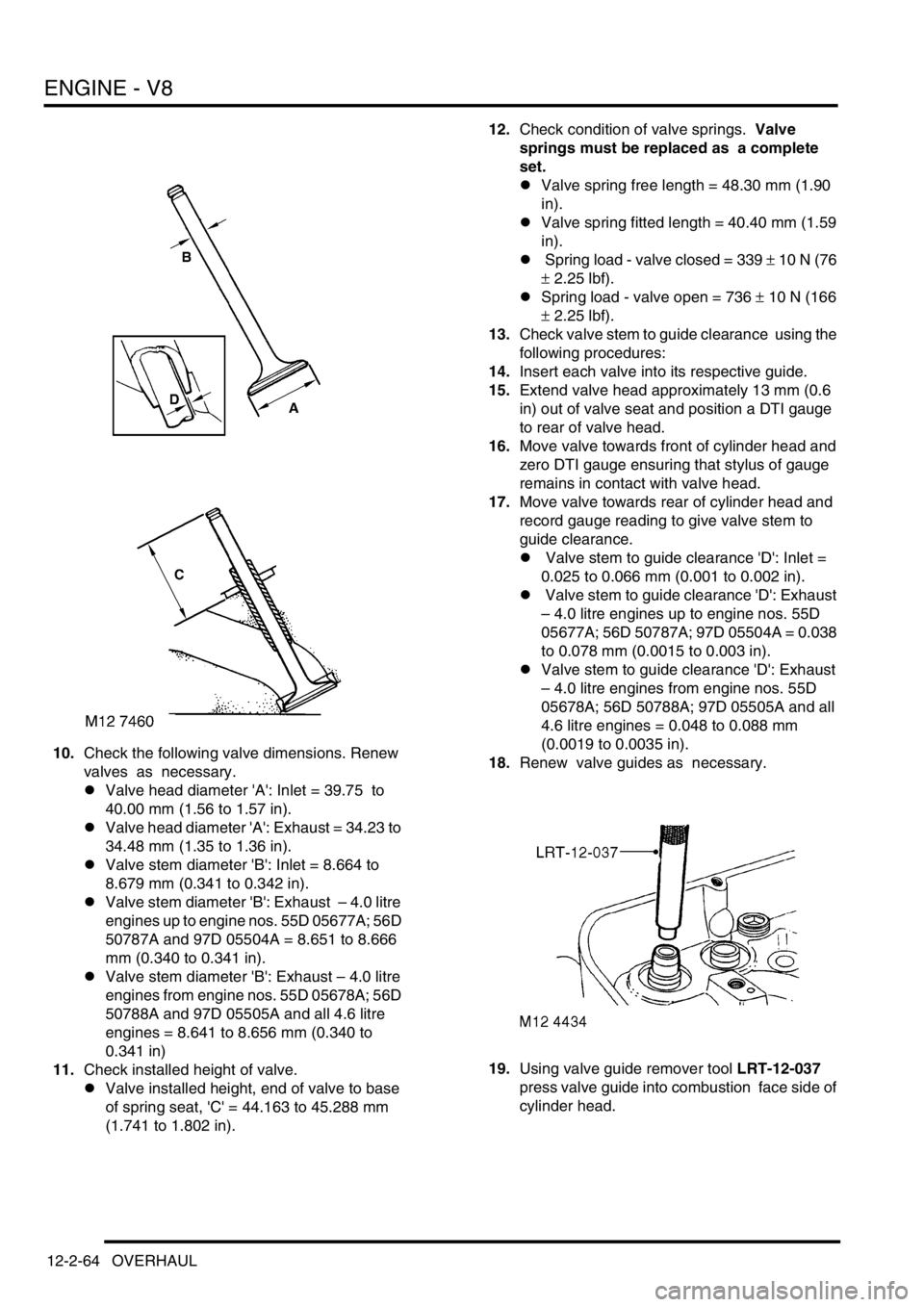
10.Check the following valve dimensions. Renew
valves as necessary.
lValve head diameter 'A': Inlet = 39.75 to
40.00 mm (1.56 to 1.57 in).
lValve head diameter 'A': Exhaust = 34.23 to
34.48 mm (1.35 to 1.36 in).
lValve stem diameter 'B': Inlet = 8.664 to
8.679 mm (0.341 to 0.342 in).
lValve stem diameter 'B': Exhaust – 4.0 litre
engines up to engine nos. 55D 05677A; 56D
50787A and 97D 05504A = 8.651 to 8.666
mm (0.340 to 0.341 in).
lValve stem diameter 'B': Exhaust – 4.0 litre
engines from engine nos. 55D 05678A; 56D
50788A and 97D 05505A and all 4.6 litre
engines = 8.641 to 8.656 mm (0.340 to
0.341 in)
11.Check installed height of valve.
lValve installed height, end of valve to base
of spring seat, 'C' = 44.163 to 45.288 mm
(1.741 to 1.802 in).12.Check condition of valve springs. Valve
springs must be replaced as a complete
set.
lValve spring free length = 48.30 mm (1.90
in).
lValve spring fitted length = 40.40 mm (1.59
in).
l Spring load - valve closed = 339
± 10 N (76
± 2.25 lbf).
lSpring load - valve open = 736
± 10 N (166
± 2.25 lbf).
13.Check valve stem to guide clearance using the
following procedures:
14.Insert each valve into its respective guide.
15.Extend valve head approximately 13 mm (0.6
in) out of valve seat and position a DTI gauge
to rear of valve head.
16.Move valve towards front of cylinder head and
zero DTI gauge ensuring that stylus of gauge
remains in contact with valve head.
17.Move valve towards rear of cylinder head and
record gauge reading to give valve stem to
guide clearance.
l Valve stem to guide clearance 'D': Inlet =
0.025 to 0.066 mm (0.001 to 0.002 in).
l Valve stem to guide clearance 'D': Exhaust
– 4.0 litre engines up to engine nos. 55D
05677A; 56D 50787A; 97D 05504A = 0.038
to 0.078 mm (0.0015 to 0.003 in).
lValve stem to guide clearance 'D': Exhaust
– 4.0 litre engines from engine nos. 55D
05678A; 56D 50788A; 97D 05505A and all
4.6 litre engines = 0.048 to 0.088 mm
(0.0019 to 0.0035 in).
18.Renew valve guides as necessary.
19.Using valve guide remover tool LRT-12-037
press valve guide into combustion face side of
cylinder head.
Page 311 of 1672
ENGINE - V8
12-2-68 OVERHAUL
Inspect
1.Clean carbon from piston. Inspect piston for
distortion, cracks and burning.
2.Remove piston rings from piston.
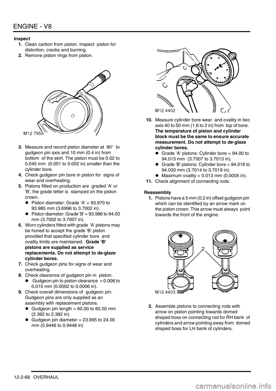
3.Measure and record piston diameter at 90
° to
gudgeon pin axis and 10 mm (0.4 in) from
bottom of the skirt. The piston must be 0.02 to
0.045 mm (0.001 to 0.002 in) smaller than the
cylinder bore.
4.Check gudgeon pin bore in piston for signs of
wear and overheating.
5.Pistons fitted on production are graded 'A' or
'B', the grade letter is stamped on the piston
crown.
lPiston diameter: Grade 'A' = 93.970 to
93.985 mm (3.6996 to 3.7002 in).
lPiston diameter: Grade 'B' = 93.986 to 94.00
mm (3.7002 to 3.7007 in).
6.Worn cylinders fitted with grade 'A' pistons may
be honed to accept the grade 'B' piston
provided that specified cylinder bore and
ovality limits are maintained. Grade 'B'
pistons are supplied as service
replacements. Do not attempt to de-glaze
cylinder bores.
7.Check gudgeon pins for signs of wear and
overheating.
8.Check clearance of gudgeon pin in piston.
l Gudgeon pin to piston clearance = 0.006 to
0.015 mm (0.0002 to 0.0006 in).
9.Check overall dimensions of gudgeon pin.
Gudgeon pins are only supplied as an
assembly with replacement pistons.
lGudgeon pin length = 60.00 to 60.50 mm
(2.362 to 2.382 in).
lGudgeon pin diameter = 23.995 to 24.00
mm (0.9446 to 0.9448 in)10.Measure cylinder bore wear and ovality in two
axis 40 to 50 mm (1.6 to 2 in) from top of bore.
The temperature of piston and cylinder
block must be the same to ensure accurate
measurement. Do not attempt to de-glaze
cylinder bores.
lGrade 'A' pistons: Cylinder bore = 94.00 to
94.015 mm (3.7007 to 3.7013 in).
lGrade 'B' pistons: Cylinder bore = 94.016 to
94.030 mm (3.7014 to 3.7019 in).
lMaximum ovality = 0.013 mm (0.0005 in).
11.Check alignment of connecting rods.
Reassembly
1.Pistons have a 5 mm (0.2 in) offset gudgeon pin
which can be identified by an arrow mark on
the piston crown. This arrow must always point
towards the front of the engine.
2.Assemble pistons to connecting rods with
arrow on piston pointing towards domed
shaped boss on connecting rod for RH bank of
cylinders and arrow pointing away from domed
shaped boss for LH bank of cylinders.
Page 312 of 1672
ENGINE - V8
OVERHAUL 12-2-69
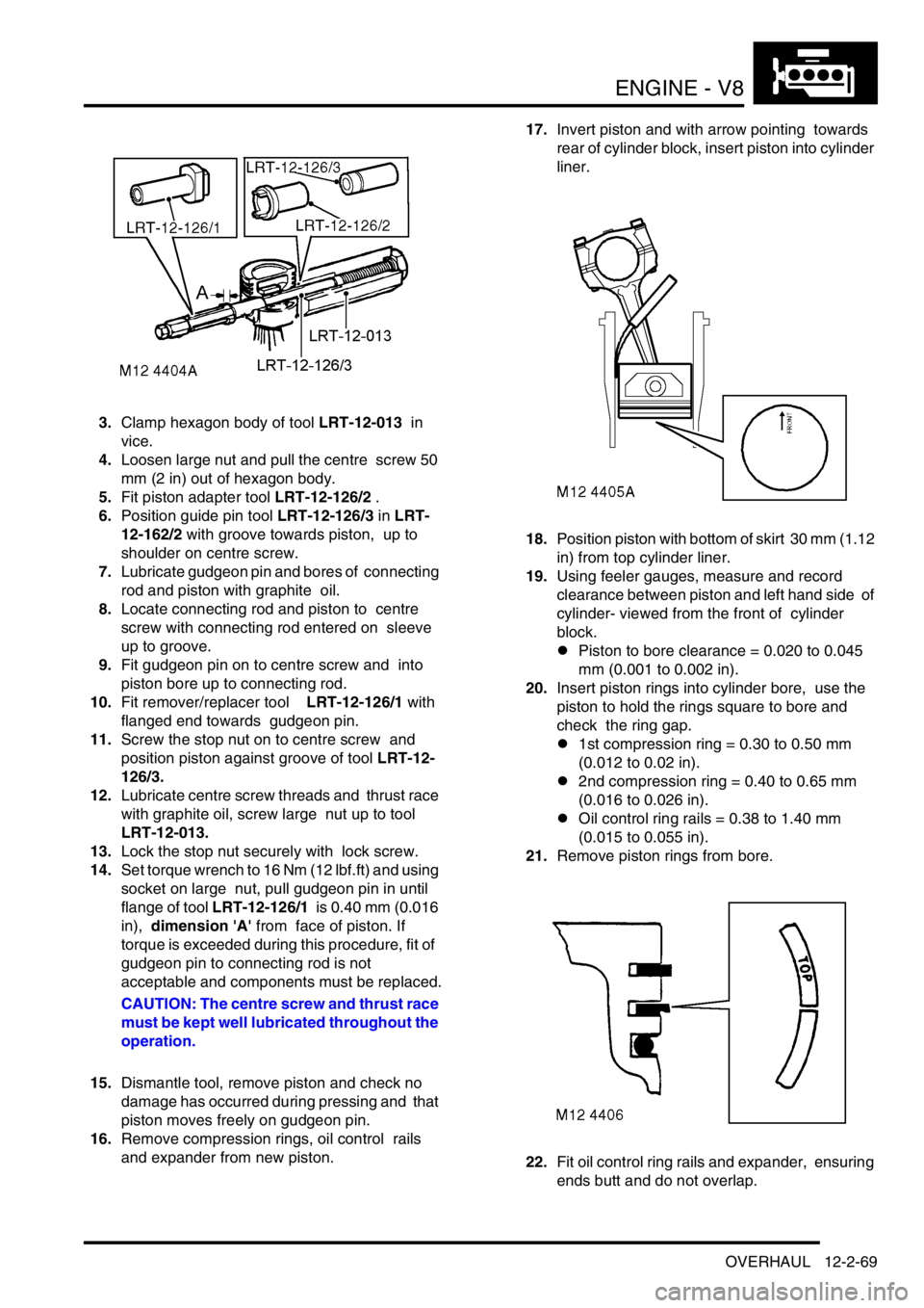
3.Clamp hexagon body of tool LRT-12-013 in
vice.
4.Loosen large nut and pull the centre screw 50
mm (2 in) out of hexagon body.
5.Fit piston adapter tool LRT-12-126/2 .
6.Position guide pin tool LRT-12-126/3 in LRT-
12-162/2 with groove towards piston, up to
shoulder on centre screw.
7.Lubricate gudgeon pin and bores of connecting
rod and piston with graphite oil.
8.Locate connecting rod and piston to centre
screw with connecting rod entered on sleeve
up to groove.
9.Fit gudgeon pin on to centre screw and into
piston bore up to connecting rod.
10.Fit remover/replacer tool LRT-12-126/1 with
flanged end towards gudgeon pin.
11.Screw the stop nut on to centre screw and
position piston against groove of tool LRT-12-
126/3.
12.Lubricate centre screw threads and thrust race
with graphite oil, screw large nut up to tool
LRT-12-013.
13.Lock the stop nut securely with lock screw.
14.Set torque wrench to 16 Nm (12 lbf.ft) and using
socket on large nut, pull gudgeon pin in until
flange of tool LRT-12-126/1 is 0.40 mm (0.016
in), dimension 'A' from face of piston. If
torque is exceeded during this procedure, fit of
gudgeon pin to connecting rod is not
acceptable and components must be replaced.
CAUTION: The centre screw and thrust race
must be kept well lubricated throughout the
operation.
15.Dismantle tool, remove piston and check no
damage has occurred during pressing and that
piston moves freely on gudgeon pin.
16.Remove compression rings, oil control rails
and expander from new piston. 17.Invert piston and with arrow pointing towards
rear of cylinder block, insert piston into cylinder
liner.
18.Position piston with bottom of skirt 30 mm (1.12
in) from top cylinder liner.
19.Using feeler gauges, measure and record
clearance between piston and left hand side of
cylinder- viewed from the front of cylinder
block.
lPiston to bore clearance = 0.020 to 0.045
mm (0.001 to 0.002 in).
20.Insert piston rings into cylinder bore, use the
piston to hold the rings square to bore and
check the ring gap.
l1st compression ring = 0.30 to 0.50 mm
(0.012 to 0.02 in).
l2nd compression ring = 0.40 to 0.65 mm
(0.016 to 0.026 in).
lOil control ring rails = 0.38 to 1.40 mm
(0.015 to 0.055 in).
21.Remove piston rings from bore.
22.Fit oil control ring rails and expander, ensuring
ends butt and do not overlap.
Page 313 of 1672
ENGINE - V8
12-2-70 OVERHAUL
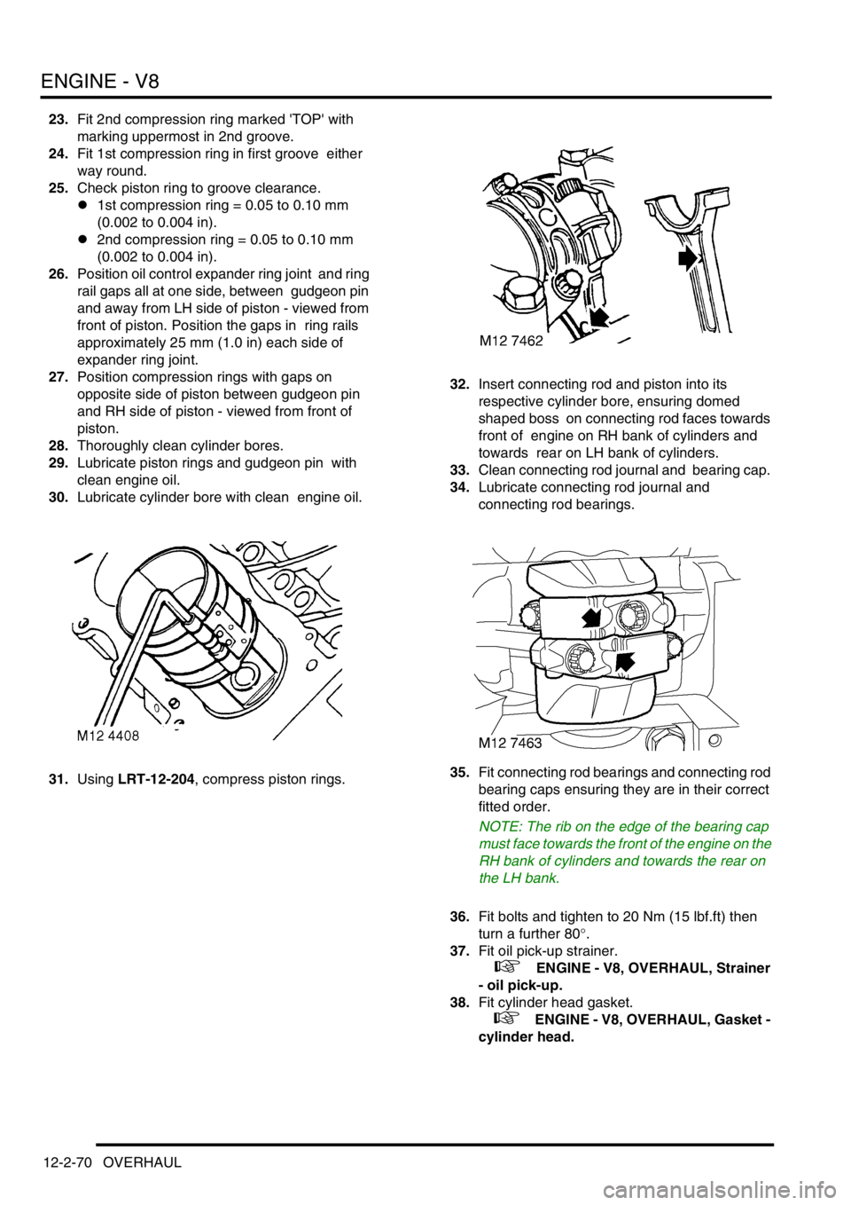
23.Fit 2nd compression ring marked 'TOP' with
marking uppermost in 2nd groove.
24.Fit 1st compression ring in first groove either
way round.
25.Check piston ring to groove clearance.
l1st compression ring = 0.05 to 0.10 mm
(0.002 to 0.004 in).
l2nd compression ring = 0.05 to 0.10 mm
(0.002 to 0.004 in).
26.Position oil control expander ring joint and ring
rail gaps all at one side, between gudgeon pin
and away from LH side of piston - viewed from
front of piston. Position the gaps in ring rails
approximately 25 mm (1.0 in) each side of
expander ring joint.
27.Position compression rings with gaps on
opposite side of piston between gudgeon pin
and RH side of piston - viewed from front of
piston.
28.Thoroughly clean cylinder bores.
29.Lubricate piston rings and gudgeon pin with
clean engine oil.
30.Lubricate cylinder bore with clean engine oil.
31.Using LRT-12-204, compress piston rings. 32.Insert connecting rod and piston into its
respective cylinder bore, ensuring domed
shaped boss on connecting rod faces towards
front of engine on RH bank of cylinders and
towards rear on LH bank of cylinders.
33.Clean connecting rod journal and bearing cap.
34.Lubricate connecting rod journal and
connecting rod bearings.
35.Fit connecting rod bearings and connecting rod
bearing caps ensuring they are in their correct
fitted order.
NOTE: The rib on the edge of the bearing cap
must face towards the front of the engine on the
RH bank of cylinders and towards the rear on
the LH bank.
36.Fit bolts and tighten to 20 Nm (15 lbf.ft) then
turn a further 80
°.
37.Fit oil pick-up strainer.
+ ENGINE - V8, OVERHAUL, Strainer
- oil pick-up.
38.Fit cylinder head gasket.
+ ENGINE - V8, OVERHAUL, Gasket -
cylinder head.
Page 314 of 1672
ENGINE - V8
OVERHAUL 12-2-71
Bearings - connecting rods
$% 12.17.16.01
Disassembly
1.Remove oil pick up strainer.
+ ENGINE - V8, OVERHAUL, Strainer
- oil pick-up.
2.Suitably mark cylinder reference number on
each connecting rod bearing cap.
3.Remove 2 bolts securing each connecting rod
bearing cap, remove caps and recover
connecting rod bearings.
CAUTION: Keep bearing caps, bearings and
bolts in their fitted order.
4.Push each connecting rod up cylinder bore
until connecting rods are clear of crankshaft
journals.
CAUTION: Ensure that connecting rods do
not contact cylinder bores.
5.Remove bearing shells from each connecting
rod.
Inspect
1.Clean crankshaft journals and bearing
locations in connecting rods.
2.Inspect connecting rod bearings for wear and
renew if necessary. Connecting rod bearings
are available in two oversizes.
lConnecting rod bearing 1st oversize = 0.254
mm (0.01 in).
lConnecting rod bearing 2nd oversize =
0.508 mm (0.02 in).3.Check crankshaft big-end journals for wear and
scoring. Measure for ovality; taking 3
measurements at 120
° intervals at each end
and at centre of journals.
lStandard journal = 55.500 to 55.513 mm
(2.20 to 2.22 in).
l1st undersize journal - 0.254 mm (0.01 in) =
55.246 to 55.259 mm (2.17 to 2.18 in).
l2nd undersize journal - 0.508 mm (0.02 in)
= 54.992 to 55.005 mm (2.16 to 2.165 in).
lJournal - max. ovality = 0.040 mm (0.002 in)
Reassembly
1.Clean connecting rod caps.
2.Lubricate connecting rod journals and bearing
shells with clean engine oil.
3.Fit bearing shells to connecting rods and caps.
4.Rotate crankshaft until connecting rod journals
are correctly positioned.
5.Taking care not to displace bearing shells, pull
connecting rods on to crankshaft journals.
6.Check that bearing shells are correctly located
in connecting rod bearing caps.
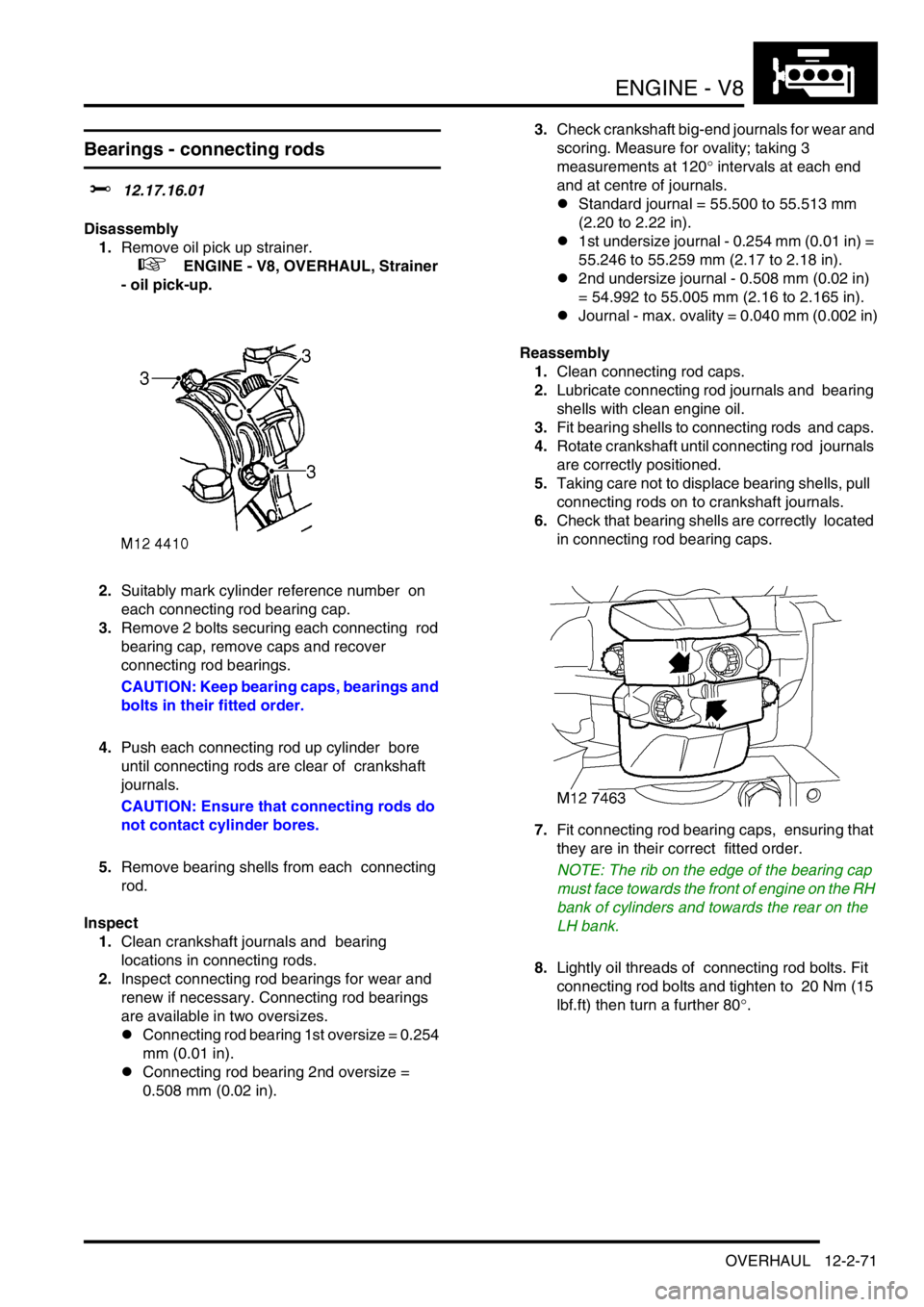
7.Fit connecting rod bearing caps, ensuring that
they are in their correct fitted order.
NOTE: The rib on the edge of the bearing cap
must face towards the front of engine on the RH
bank of cylinders and towards the rear on the
LH bank.
8.Lightly oil threads of connecting rod bolts. Fit
connecting rod bolts and tighten to 20 Nm (15
lbf.ft) then turn a further 80
°.
Page 355 of 1672
EMISSION CONTROL - V8
17-2-18 DESCRIPTION AND OPERATION
EVAP (charcoal) canister
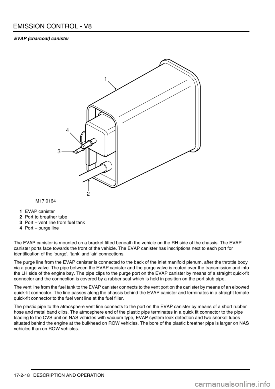
1EVAP canister
2Port to breather tube
3Port – vent line from fuel tank
4Port – purge line
The EVAP canister is mounted on a bracket fitted beneath the vehicle on the RH side of the chassis. The EVAP
canister ports face towards the front of the vehicle. The EVAP canister has inscriptions next to each port for
identification of the 'purge', 'tank' and 'air' connections.
The purge line from the EVAP canister is connected to the back of the inlet manifold plenum, after the throttle body
via a purge valve. The pipe between the EVAP canister and the purge valve is routed over the transmission and into
the LH side of the engine bay. The pipe clips to the purge port on the EVAP canister by means of a straight quick-fit
connector and the connection is covered by a rubber seal which is held in position on the port stub pipe.
The vent line from the fuel tank to the EVAP canister connects to the vent port on the canister by means of an elbowed
quick-fit connector. The line passes along the chassis behind the EVAP canister and terminates in a straight female
quick-fit connector to the fuel vent line at the fuel filler.
The plastic pipe to the atmosphere vent line connects to the port on the EVAP canister by means of a short rubber
hose and metal band clips. The atmosphere end of the plastic pipe terminates in a quick fit connector to the pipe
leading to the CVS unit on NAS vehicles with vacuum type, EVAP system leak detection and two snorkel tubes
situated behind the engine at the bulkhead on ROW vehicles. The bore of the plastic breather pipe is larger on NAS
vehicles than on ROW vehicles.
Page 369 of 1672
EMISSION CONTROL - V8
17-2-32 DESCRIPTION AND OPERATION
Vacuum reservoir
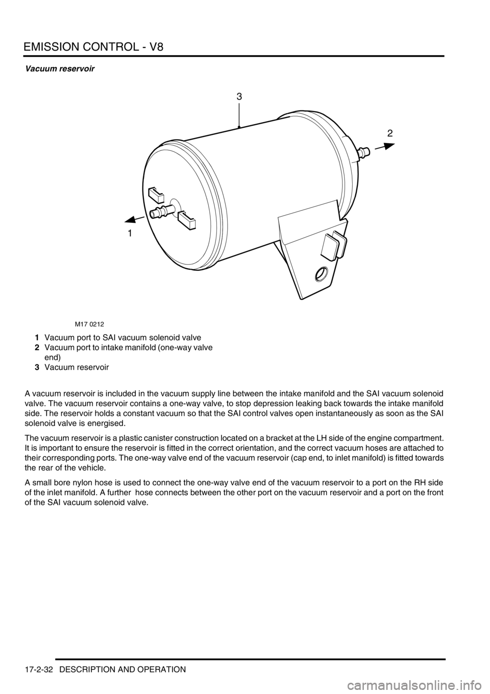
1Vacuum port to SAI vacuum solenoid valve
2Vacuum port to intake manifold (one-way valve
end)
3Vacuum reservoir
A vacuum reservoir is included in the vacuum supply line between the intake manifold and the SAI vacuum solenoid
valve. The vacuum reservoir contains a one-way valve, to stop depression leaking back towards the intake manifold
side. The reservoir holds a constant vacuum so that the SAI control valves open instantaneously as soon as the SAI
solenoid valve is energised.
The vacuum reservoir is a plastic canister construction located on a bracket at the LH side of the engine compartment.
It is important to ensure the reservoir is fitted in the correct orientation, and the correct vacuum hoses are attached to
their corresponding ports. The one-way valve end of the vacuum reservoir (cap end, to inlet manifold) is fitted towards
the rear of the vehicle.
A small bore nylon hose is used to connect the one-way valve end of the vacuum reservoir to a port on the RH side
of the inlet manifold. A further hose connects between the other port on the vacuum reservoir and a port on the front
of the SAI vacuum solenoid valve.
M17 0212
1
2
3
Page 450 of 1672
ENGINE MANAGEMENT SYSTEM - TD5
REPAIRS 18-1-57
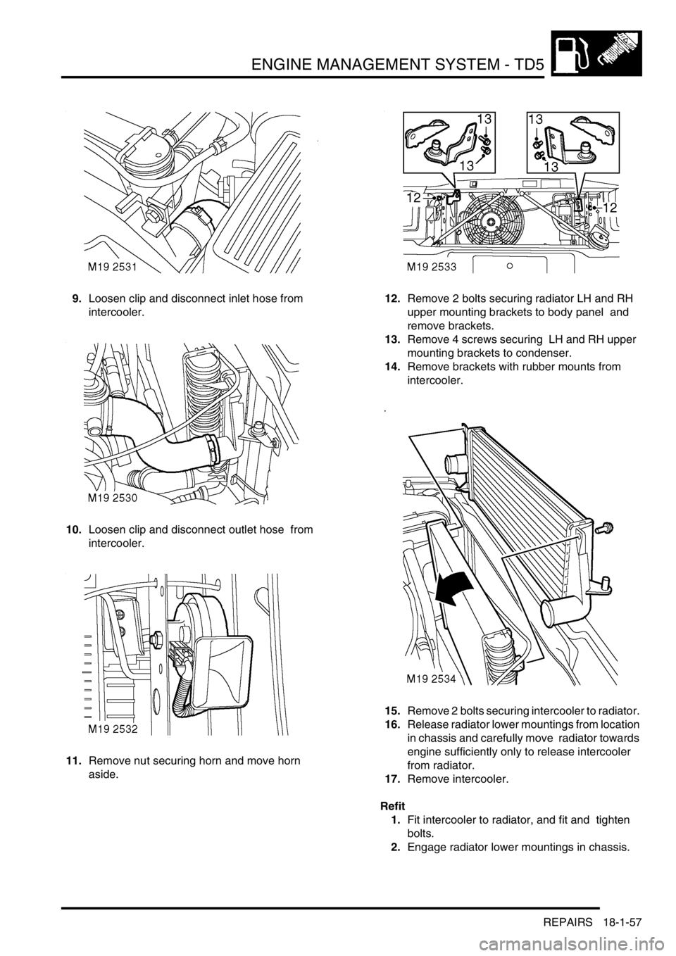
9.Loosen clip and disconnect inlet hose from
intercooler.
10.Loosen clip and disconnect outlet hose from
intercooler.
11.Remove nut securing horn and move horn
aside. 12.Remove 2 bolts securing radiator LH and RH
upper mounting brackets to body panel and
remove brackets.
13.Remove 4 screws securing LH and RH upper
mounting brackets to condenser.
14.Remove brackets with rubber mounts from
intercooler.
15.Remove 2 bolts securing intercooler to radiator.
16.Release radiator lower mountings from location
in chassis and carefully move radiator towards
engine sufficiently only to release intercooler
from radiator.
17.Remove intercooler.
Refit
1.Fit intercooler to radiator, and fit and tighten
bolts.
2.Engage radiator lower mountings in chassis.
Page 469 of 1672
ENGINE MANAGEMENT SYSTEM - V8
18-2-12 DESCRIPTION AND OPERATION
Connector 5 (C0638): This connector contains 9 pins and is used to control the ignition system. The ignition coils are
supplied with power and a switching earth completes the circuit.
Pin out details connector C0638
Crankshaft speed and Position (CKP) sensor (C0168)
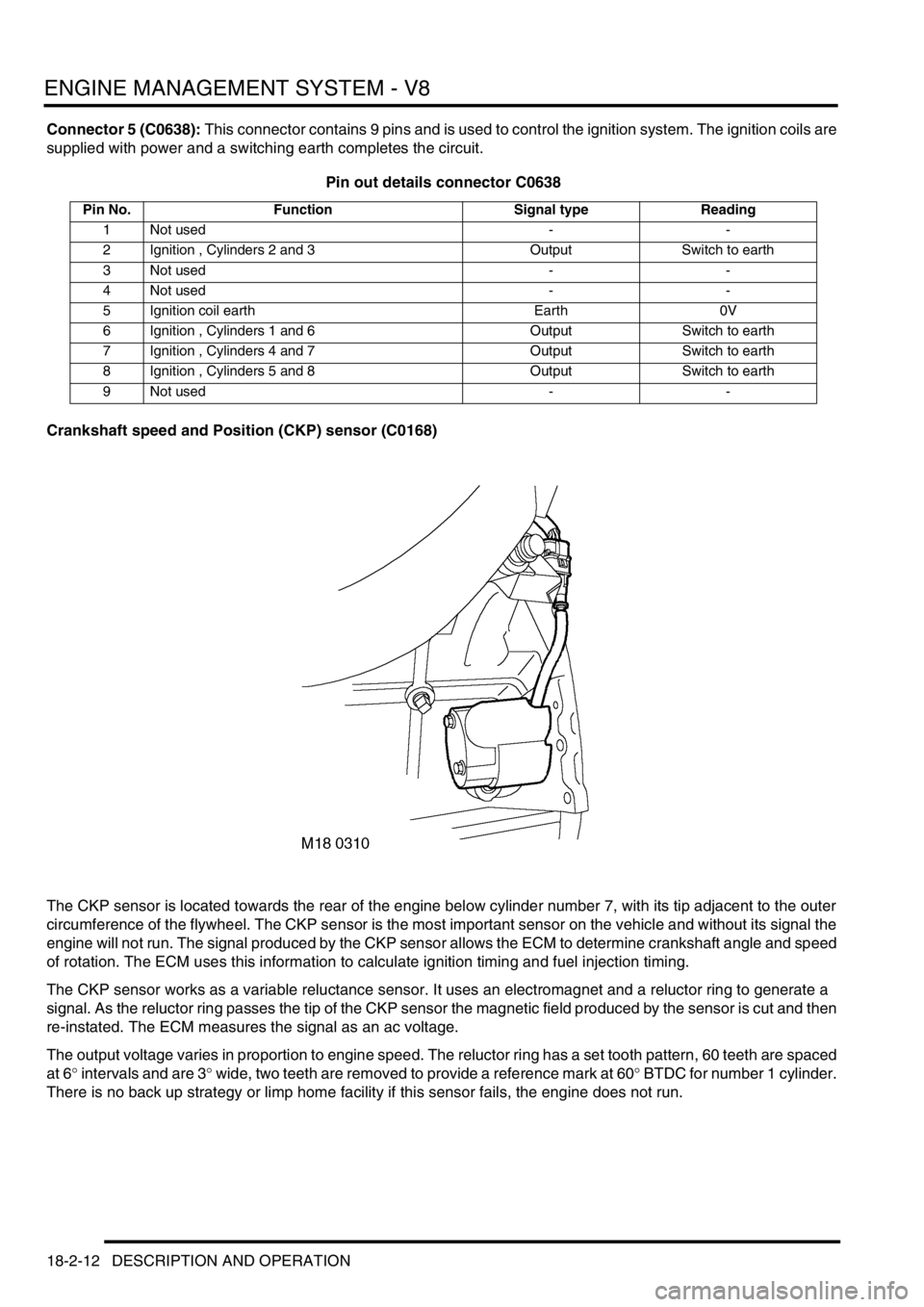
The CKP sensor is located towards the rear of the engine below cylinder number 7, with its tip adjacent to the outer
circumference of the flywheel. The CKP sensor is the most important sensor on the vehicle and without its signal the
engine will not run. The signal produced by the CKP sensor allows the ECM to determine crankshaft angle and speed
of rotation. The ECM uses this information to calculate ignition timing and fuel injection timing.
The CKP sensor works as a variable reluctance sensor. It uses an electromagnet and a reluctor ring to generate a
signal. As the reluctor ring passes the tip of the CKP sensor the magnetic field produced by the sensor is cut and then
re-instated. The ECM measures the signal as an ac voltage.
The output voltage varies in proportion to engine speed. The reluctor ring has a set tooth pattern, 60 teeth are spaced
at 6
° intervals and are 3° wide, two teeth are removed to provide a reference mark at 60° BTDC for number 1 cylinder.
There is no back up strategy or limp home facility if this sensor fails, the engine does not run.
Pin No. Function Signal type Reading
1 Not used - -
2 Ignition , Cylinders 2 and 3 Output Switch to earth
3 Not used - -
4 Not used - -
5 Ignition coil earth Earth 0V
6 Ignition , Cylinders 1 and 6 Output Switch to earth
7 Ignition , Cylinders 4 and 7 Output Switch to earth
8 Ignition , Cylinders 5 and 8 Output Switch to earth
9 Not used - -
Page 484 of 1672

ENGINE MANAGEMENT SYSTEM - V8
DESCRIPTION AND OPERATION 18-2-27
The HO2S uses zirconium contained in a galvanic cell surrounded by a gas permeable ceramic, this produces an
output voltage proportional to the ratio difference between the oxygen in the exhaust gases and to the ambient
oxygen.
The HO
2S operates at approximately 350 °C (662 °F). To achieve this temperature the HO2S incorporate a heating
element which is controlled by a PWM signal from the ECM. The elements are activated immediately after engine
starts and also under low engine load conditions when the exhaust gas temperature is insufficient to maintain the
required HO
2S temperature. If the heater fails, the ECM will not allow closed loop fuelling to be implemented until the
sensor has achieved the required temperature.
This value equates to an HO
2S output of 450 to 500 mV. A richer mixture can be shown as λ = 0.97, this pushes the
HO
2S output voltage towards 1000 mV. A leaner mixture can be shown as λ = 1.10, this pushes the HO2S output
voltage towards 100 mV.
From cold start, the ECM runs an open loop fuelling strategy. The ECM keeps this strategy in place until the HO
2S is
at a working temperature of 350
°C (662 °F). At this point the ECM starts to receive HO2S information and it can then
switch into closed loop fuelling as part of its adaptive strategy. The maximum working temperature of the tip of the
HO
2S is 930 °C (1706 °F), temperatures above this will damage the sensor.
HO
2S age with use, this increases their response time to switch from rich to lean and from lean to rich. This can lead
to increased exhaust emissions over a period of time. The switching time of the upstream sensors are monitored by
the ECM. If a pre-determined threshold is exceeded, a failure is detected and the MIL illuminated.
+ EMISSION CONTROL - V8, DESCRIPTION AND OPERATION, Exhaust emission control system.
Input/Output
The upstream and downstream HO
2S are colour coded to prevent incorrect fitting. The tips of the upstream sensors
are physically different to the tips of the downstream sensors.
The HO
2S are colour coded as follows:
lUpstream sensors (both banks) - orange.
lDownstream sensors (both banks) - grey.
The four HO
2S have a direct battery supply to the heater via fuse 2 located in the engine compartment fuse box.
The heater is driven by the ECM providing an earth path for the circuit as follows:
lUpstream LH bank via pin 19 of connector C0635 of the ECM.
lUpstream RH bank via pin 13 of connector C0635 of the ECM.
lDownstream LH bank via pin 7 of connector C0635 of the ECM.
lDownstream RH bank via pin 1 of connector C0635 of the ECM.
The HO
2S output signal is measured by the ECM as follows:
lUpstream LH bank via pin 15 of connector C0635 of the ECM.
lUpstream RH bank via pin 16 of connector C0635 of the ECM.
lDownstream LH bank via pin 17 of connector C0635 of the ECM.
lDownstream RH bank via pin 14 of connector C0635 of the ECM.
The HO
2S earth path for the signal is supplied by the ECM as follows:
lUpstream LH bank via pin 9 of connector C0635 of the ECM.
lUpstream RH bank via pin 10 of connector C0635 of the ECM.
lDownstream LH bank via pin 11 of connector C0635 of the ECM.
lDownstream RH bank via pin 8 of connector C0635 of the ECM.
The HO
2S voltage is difficult to measure using a multimeter, the output can be monitored using TestBook. A rich
mixture would read 500 to 1000 mV, a weak mixture would read 100 mV to 500 mV, the reading should switch from
rich to weak. The open loop default voltage is 450 mV, this is used by the ECM to set the air/ fuel ratio until the tip of
the HO
2S reaches operating temperature.