tow LAND ROVER DISCOVERY 2002 User Guide
[x] Cancel search | Manufacturer: LAND ROVER, Model Year: 2002, Model line: DISCOVERY, Model: LAND ROVER DISCOVERY 2002Pages: 1672, PDF Size: 46.1 MB
Page 104 of 1672
LIFTING AND TOWING
08-3
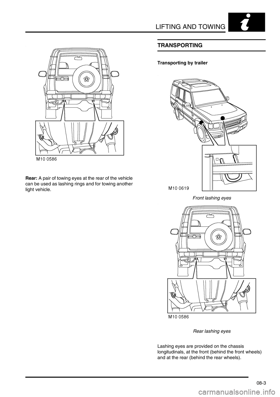
Rear: A pair of towing eyes at the rear of the vehicle
can be used as lashing rings and for towing another
light vehicle.
TRANSPORTING
Transporting by trailer
Front lashing eyes
Rear lashing eyes
Lashing eyes are provided on the chassis
longitudinals, at the front (behind the front wheels)
and at the rear (behind the rear wheels).
Page 105 of 1672
LIFTING AND TOWING
08-4
DO NOT secure lashing hooks or trailer fixings to
any other part of the vehicle.
Position the vehicle on the trailer and apply the
handbrake. Select neutral in the manual gearbox ('N'
on automatic gearbox). Selecting 'N' will prevent
damage to the parking pawl in the automatic
gearbox.
Page 136 of 1672
MAINTENANCE
PROCEDURES 10-27
2.Check security of fixings.
+ TORQUE WRENCH SETTINGS,
Front suspension.
+ TORQUE WRENCH SETTINGS, Rear
suspension.
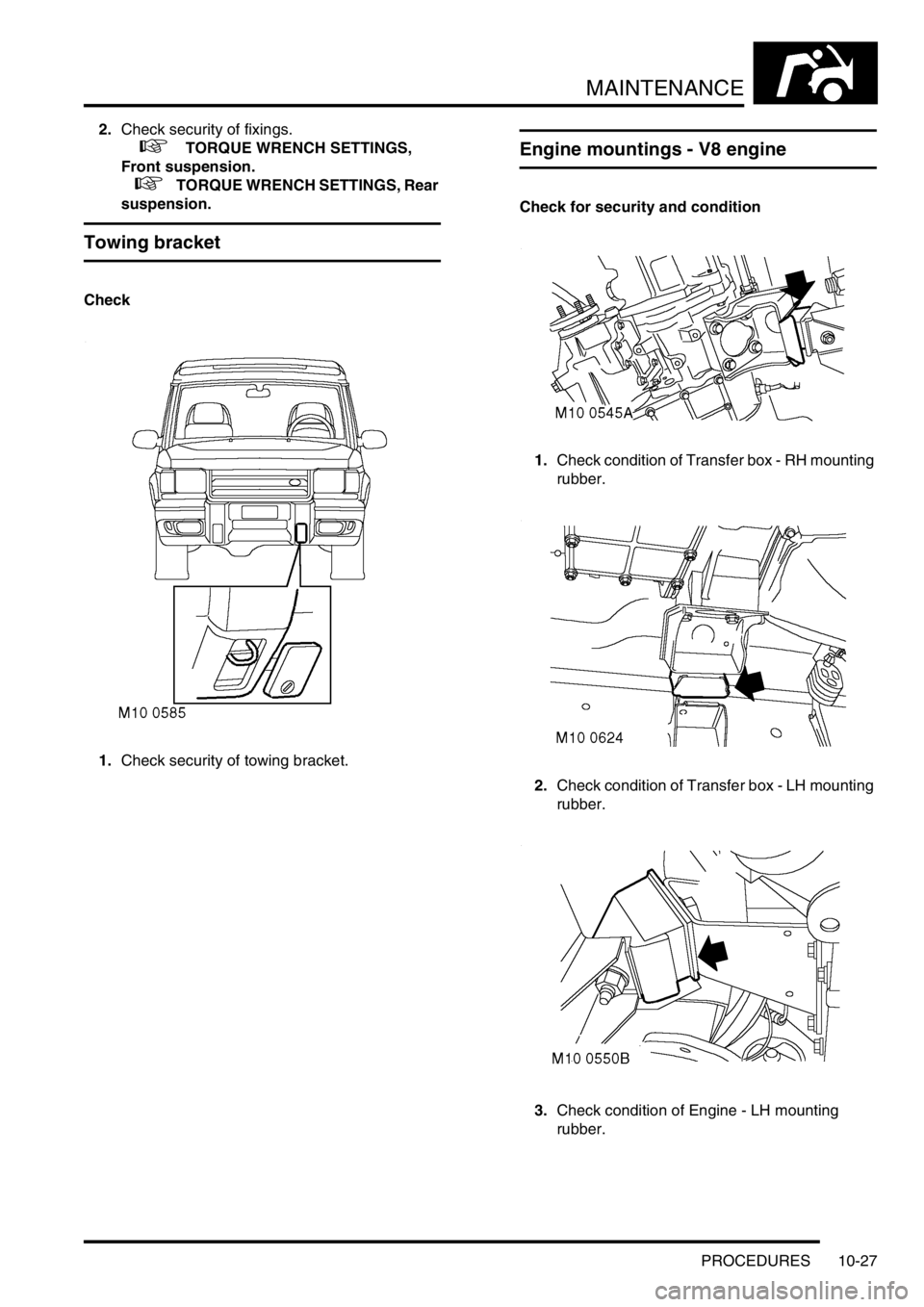
Towing bracket
Check
1.Check security of towing bracket.
Engine mountings - V8 engine
Check for security and condition
1.Check condition of Transfer box - RH mounting
rubber.
2.Check condition of Transfer box - LH mounting
rubber.
3.Check condition of Engine - LH mounting
rubber.
Page 173 of 1672

ENGINE - TD5
12-1-34 DESCRIPTION AND OPERATION
A tapping towards the right hand side of the cylinder head diverts oil supply from the cast-in groove down to a stub
pipe which attaches to a feed line to the vacuum pump. An hydraulic tensioner is located below the vacuum stub pipe
which receives oil through a small hole in the side of the tensioner body to force a plunger against a plastic faced
adjuster shoe for timing chain tensioning. Oil from the vacuum pump is returned to a port in the timing chain cover via
a short hose which connects to stub pipes at both ends using spring clips.
Page 218 of 1672
ENGINE - TD5
OVERHAUL 12-1-79
24.Compare figures obtained with camshaft
bearing clearance:
lCamshaft bearing clearance = 0.04 to 0.10
mm (0.002 to 0.004 in)
25.If any bearing clearance is found to exceed
figures given, repeat the above procedures
using a new camshaft. If, after repeating the
clearance check using a new camshaft the
clearances are still excessive, a new cylinder
head and camshaft carrier assembly must be
fitted.
26.Remove all traces of Plastigage using an oily
cloth, do not use a scraper.
27.On completion, discard camshaft carrier bolts.
28.Check free length of valve springs:
lFree length = 46.75 to 47.25 mm (1.84 to
1.86 in)
29. Replace valve springs as a set, if springs
are to be refitted, keep them in their fitted
order.
30.Clean carbon from valves, check valves for
burning, pitting or cracking; replace as
necessary.
31.Clean carbon from valve seat inserts, remove
all loose particles on completion.
32.Check valve seat inserts for pitting and burning.
It is not permissible to recut or replace valve
seat inserts.
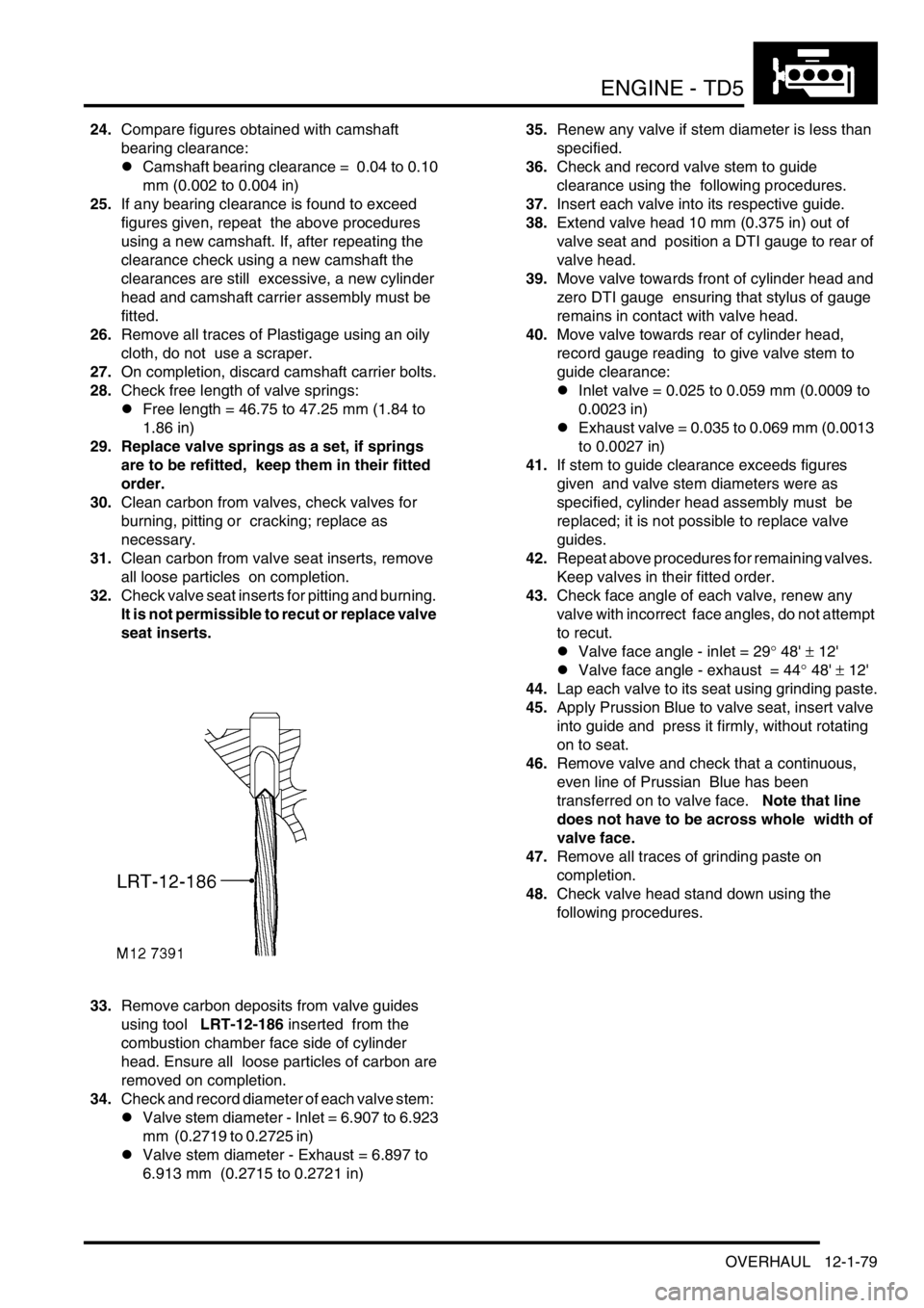
33.Remove carbon deposits from valve guides
using tool LRT-12-186 inserted from the
combustion chamber face side of cylinder
head. Ensure all loose particles of carbon are
removed on completion.
34.Check and record diameter of each valve stem:
lValve stem diameter - Inlet = 6.907 to 6.923
mm (0.2719 to 0.2725 in)
lValve stem diameter - Exhaust = 6.897 to
6.913 mm (0.2715 to 0.2721 in)35.Renew any valve if stem diameter is less than
specified.
36.Check and record valve stem to guide
clearance using the following procedures.
37.Insert each valve into its respective guide.
38.Extend valve head 10 mm (0.375 in) out of
valve seat and position a DTI gauge to rear of
valve head.
39.Move valve towards front of cylinder head and
zero DTI gauge ensuring that stylus of gauge
remains in contact with valve head.
40.Move valve towards rear of cylinder head,
record gauge reading to give valve stem to
guide clearance:
lInlet valve = 0.025 to 0.059 mm (0.0009 to
0.0023 in)
lExhaust valve = 0.035 to 0.069 mm (0.0013
to 0.0027 in)
41.If stem to guide clearance exceeds figures
given and valve stem diameters were as
specified, cylinder head assembly must be
replaced; it is not possible to replace valve
guides.
42.Repeat above procedures for remaining valves.
Keep valves in their fitted order.
43.Check face angle of each valve, renew any
valve with incorrect face angles, do not attempt
to recut.
lValve face angle - inlet = 29
° 48' ± 12'
lValve face angle - exhaust = 44
° 48' ± 12'
44.Lap each valve to its seat using grinding paste.
45.Apply Prussion Blue to valve seat, insert valve
into guide and press it firmly, without rotating
on to seat.
46.Remove valve and check that a continuous,
even line of Prussian Blue has been
transferred on to valve face. Note that line
does not have to be across whole width of
valve face.
47.Remove all traces of grinding paste on
completion.
48.Check valve head stand down using the
following procedures.
Page 233 of 1672
ENGINE - TD5
12-1-94 OVERHAUL
15.Remove bolt and remove timing chain
adjustable guide.
16.Remove bolt and remove timing chain
lubrication jet.
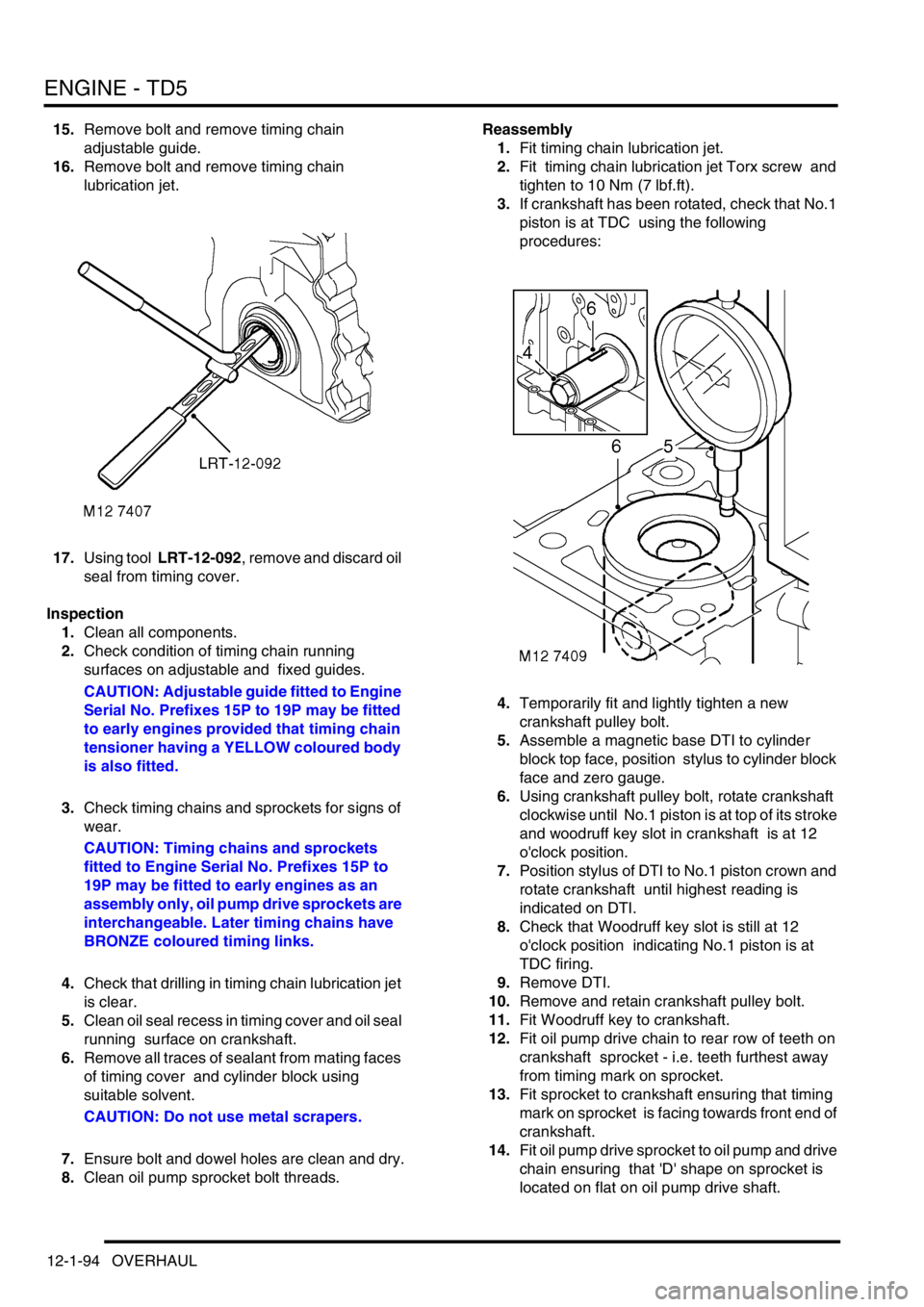
17.Using tool LRT-12-092, remove and discard oil
seal from timing cover.
Inspection
1.Clean all components.
2.Check condition of timing chain running
surfaces on adjustable and fixed guides.
CAUTION: Adjustable guide fitted to Engine
Serial No. Prefixes 15P to 19P may be fitted
to early engines provided that timing chain
tensioner having a YELLOW coloured body
is also fitted.
3.Check timing chains and sprockets for signs of
wear.
CAUTION: Timing chains and sprockets
fitted to Engine Serial No. Prefixes 15P to
19P may be fitted to early engines as an
assembly only, oil pump drive sprockets are
interchangeable. Later timing chains have
BRONZE coloured timing links.
4.Check that drilling in timing chain lubrication jet
is clear.
5.Clean oil seal recess in timing cover and oil seal
running surface on crankshaft.
6.Remove all traces of sealant from mating faces
of timing cover and cylinder block using
suitable solvent.
CAUTION: Do not use metal scrapers.
7.Ensure bolt and dowel holes are clean and dry.
8.Clean oil pump sprocket bolt threads.Reassembly
1.Fit timing chain lubrication jet.
2.Fit timing chain lubrication jet Torx screw and
tighten to 10 Nm (7 lbf.ft).
3.If crankshaft has been rotated, check that No.1
piston is at TDC using the following
procedures:
4.Temporarily fit and lightly tighten a new
crankshaft pulley bolt.
5.Assemble a magnetic base DTI to cylinder
block top face, position stylus to cylinder block
face and zero gauge.
6.Using crankshaft pulley bolt, rotate crankshaft
clockwise until No.1 piston is at top of its stroke
and woodruff key slot in crankshaft is at 12
o'clock position.
7.Position stylus of DTI to No.1 piston crown and
rotate crankshaft until highest reading is
indicated on DTI.
8.Check that Woodruff key slot is still at 12
o'clock position indicating No.1 piston is at
TDC firing.
9.Remove DTI.
10.Remove and retain crankshaft pulley bolt.
11.Fit Woodruff key to crankshaft.
12.Fit oil pump drive chain to rear row of teeth on
crankshaft sprocket - i.e. teeth furthest away
from timing mark on sprocket.
13.Fit sprocket to crankshaft ensuring that timing
mark on sprocket is facing towards front end of
crankshaft.
14.Fit oil pump drive sprocket to oil pump and drive
chain ensuring that 'D' shape on sprocket is
located on flat on oil pump drive shaft.
Page 238 of 1672
ENGINE - TD5
OVERHAUL 12-1-99
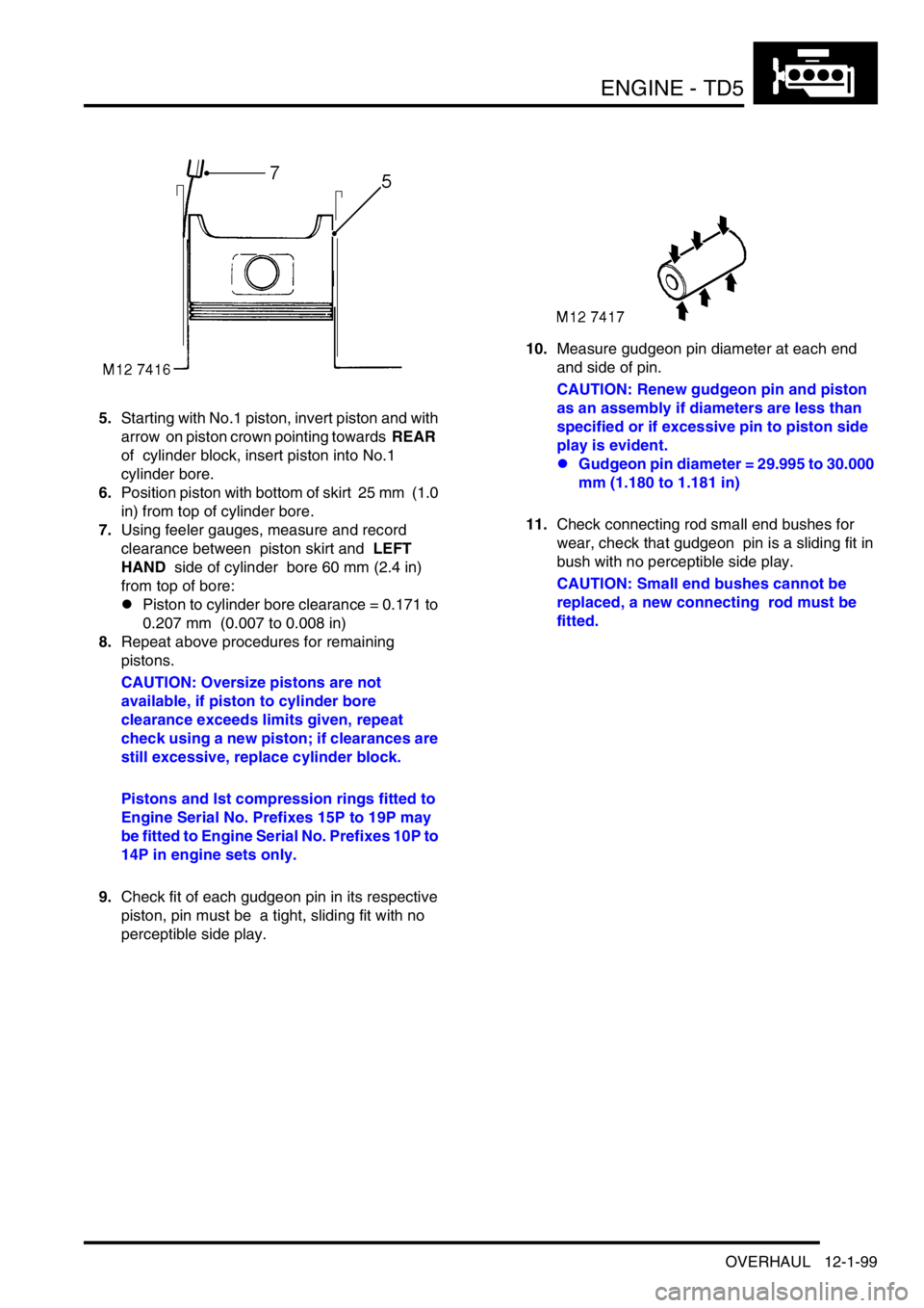
5.Starting with No.1 piston, invert piston and with
arrow on piston crown pointing towards REAR
of cylinder block, insert piston into No.1
cylinder bore.
6.Position piston with bottom of skirt 25 mm (1.0
in) from top of cylinder bore.
7.Using feeler gauges, measure and record
clearance between piston skirt and LEFT
HAND side of cylinder bore 60 mm (2.4 in)
from top of bore:
lPiston to cylinder bore clearance = 0.171 to
0.207 mm (0.007 to 0.008 in)
8.Repeat above procedures for remaining
pistons.
CAUTION: Oversize pistons are not
available, if piston to cylinder bore
clearance exceeds limits given, repeat
check using a new piston; if clearances are
still excessive, replace cylinder block.
Pistons and lst compression rings fitted to
Engine Serial No. Prefixes 15P to 19P may
be fitted to Engine Serial No. Prefixes 10P to
14P in engine sets only.
9.Check fit of each gudgeon pin in its respective
piston, pin must be a tight, sliding fit with no
perceptible side play.10.Measure gudgeon pin diameter at each end
and side of pin.
CAUTION: Renew gudgeon pin and piston
as an assembly if diameters are less than
specified or if excessive pin to piston side
play is evident.
lGudgeon pin diameter = 29.995 to 30.000
mm (1.180 to 1.181 in)
11.Check connecting rod small end bushes for
wear, check that gudgeon pin is a sliding fit in
bush with no perceptible side play.
CAUTION: Small end bushes cannot be
replaced, a new connecting rod must be
fitted.
Page 239 of 1672
ENGINE - TD5
12-1-100 OVERHAUL
12.Insert new compression and oil control rings in
turn into No.1 cylinder bore 30 mm (1.25 in)
from top of bore and check ring fitted gaps;
ensure rings are kept square to bore when
checking gaps:
l1st compression ring fitted gap = 0.30 to
0.40 mm (0.012 to 0.016 in).
l2nd compression ring fitted gap = 0.40 to
0.60 mm (0.016 to 0.024 in).
lOil control ring fitted gap = 0.25 to 0.50 mm
0.01 to 0.02 in).
CAUTION: 1st compression rings fitted to
Engine Serial No. Prefixes 10P to 14P are
not interchangeable with those fitted to
Engine Serial No. Prefixes 15P to 19P. The
later rings may, however, be fitted to early
engines together with the later type pistons
in engine sets only.
13.Repeat for each cylinder bore in turn.
CAUTION: Ensure rings are suitably
identified with the cylinder bore in which
they were checked and are fitted to the
piston for that bore.
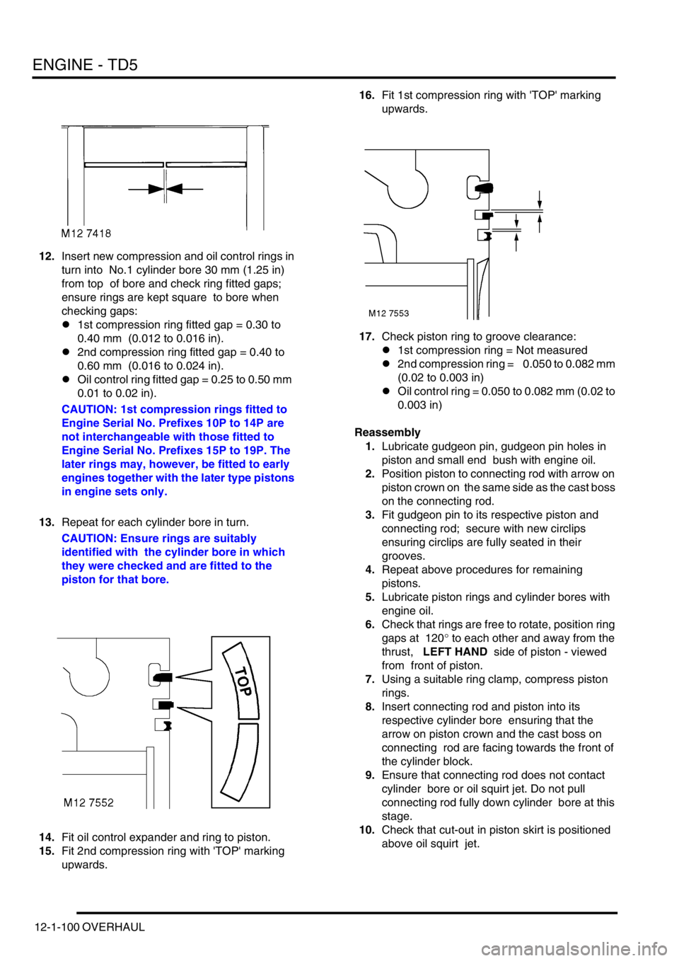
14.Fit oil control expander and ring to piston.
15.Fit 2nd compression ring with 'TOP' marking
upwards. 16.Fit 1st compression ring with 'TOP' marking
upwards.
17.Check piston ring to groove clearance:
l1st compression ring = Not measured
l2nd compression ring = 0.050 to 0.082 mm
(0.02 to 0.003 in)
lOil control ring = 0.050 to 0.082 mm (0.02 to
0.003 in)
Reassembly
1.Lubricate gudgeon pin, gudgeon pin holes in
piston and small end bush with engine oil.
2.Position piston to connecting rod with arrow on
piston crown on the same side as the cast boss
on the connecting rod.
3.Fit gudgeon pin to its respective piston and
connecting rod; secure with new circlips
ensuring circlips are fully seated in their
grooves.
4.Repeat above procedures for remaining
pistons.
5.Lubricate piston rings and cylinder bores with
engine oil.
6.Check that rings are free to rotate, position ring
gaps at 120
° to each other and away from the
thrust, LEFT HAND side of piston - viewed
from front of piston.
7.Using a suitable ring clamp, compress piston
rings.
8.Insert connecting rod and piston into its
respective cylinder bore ensuring that the
arrow on piston crown and the cast boss on
connecting rod are facing towards the front of
the cylinder block.
9.Ensure that connecting rod does not contact
cylinder bore or oil squirt jet. Do not pull
connecting rod fully down cylinder bore at this
stage.
10.Check that cut-out in piston skirt is positioned
above oil squirt jet.
Page 275 of 1672
ENGINE - V8
12-2-32 REPAIRS
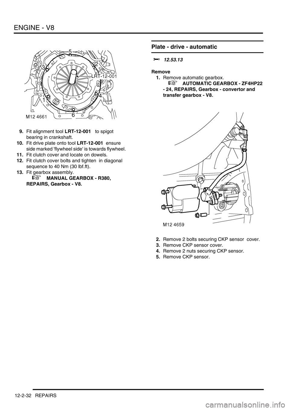
9.Fit alignment tool LRT-12-001 to spigot
bearing in crankshaft.
10.Fit drive plate onto tool LRT-12-001 ensure
side marked 'flywheel side' is towards flywheel.
11.Fit clutch cover and locate on dowels.
12.Fit clutch cover bolts and tighten in diagonal
sequence to 40 Nm (30 lbf.ft).
13.Fit gearbox assembly.
+ MANUAL GEARBOX - R380,
REPAIRS, Gearbox - V8.
Plate - drive - automatic
$% 12.53.13
Remove
1.Remove automatic gearbox.
+ AUTOMATIC GEARBOX - ZF4HP22
- 24, REPAIRS, Gearbox - convertor and
transfer gearbox - V8.
2.Remove 2 bolts securing CKP sensor cover.
3.Remove CKP sensor cover.
4.Remove 2 nuts securing CKP sensor.
5.Remove CKP sensor.
Page 283 of 1672
ENGINE - V8
12-2-40 REPAIRS
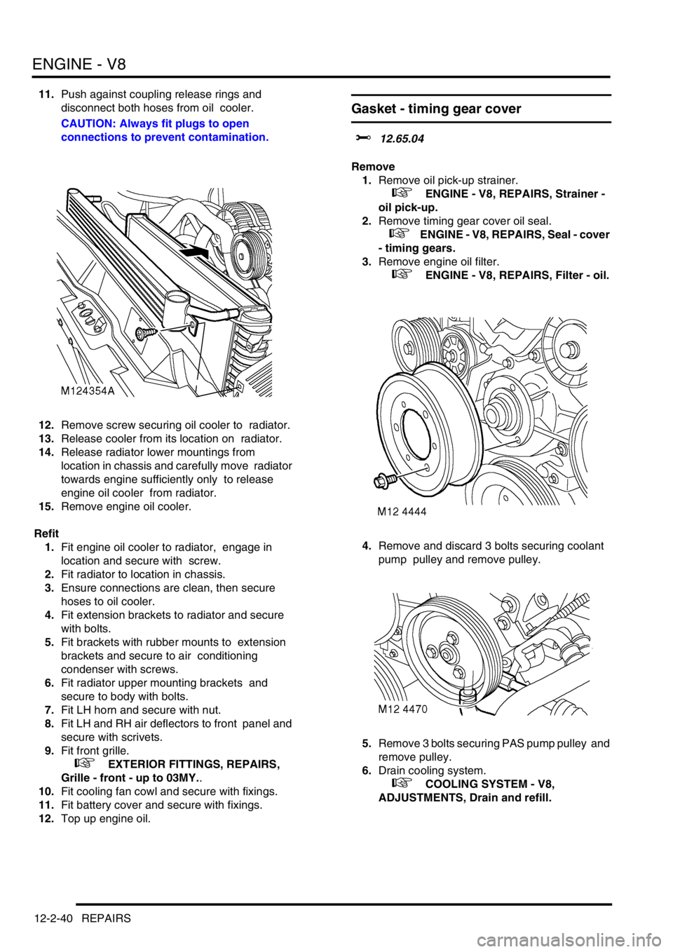
11.Push against coupling release rings and
disconnect both hoses from oil cooler.
CAUTION: Always fit plugs to open
connections to prevent contamination.
12.Remove screw securing oil cooler to radiator.
13.Release cooler from its location on radiator.
14.Release radiator lower mountings from
location in chassis and carefully move radiator
towards engine sufficiently only to release
engine oil cooler from radiator.
15.Remove engine oil cooler.
Refit
1.Fit engine oil cooler to radiator, engage in
location and secure with screw.
2.Fit radiator to location in chassis.
3.Ensure connections are clean, then secure
hoses to oil cooler.
4.Fit extension brackets to radiator and secure
with bolts.
5.Fit brackets with rubber mounts to extension
brackets and secure to air conditioning
condenser with screws.
6.Fit radiator upper mounting brackets and
secure to body with bolts.
7.Fit LH horn and secure with nut.
8.Fit LH and RH air deflectors to front panel and
secure with scrivets.
9.Fit front grille.
+ EXTERIOR FITTINGS, REPAIRS,
Grille - front - up to 03MY..
10.Fit cooling fan cowl and secure with fixings.
11.Fit battery cover and secure with fixings.
12.Top up engine oil.
Gasket - timing gear cover
$% 12.65.04
Remove
1.Remove oil pick-up strainer.
+ ENGINE - V8, REPAIRS, Strainer -
oil pick-up.
2.Remove timing gear cover oil seal.
+ ENGINE - V8, REPAIRS, Seal - cover
- timing gears.
3.Remove engine oil filter.
+ ENGINE - V8, REPAIRS, Filter - oil.
4.Remove and discard 3 bolts securing coolant
pump pulley and remove pulley.
5.Remove 3 bolts securing PAS pump pulley and
remove pulley.
6.Drain cooling system.
+ COOLING SYSTEM - V8,
ADJUSTMENTS, Drain and refill.