tow LAND ROVER DISCOVERY 2002 Service Manual
[x] Cancel search | Manufacturer: LAND ROVER, Model Year: 2002, Model line: DISCOVERY, Model: LAND ROVER DISCOVERY 2002Pages: 1672, PDF Size: 46.1 MB
Page 730 of 1672
MANUAL GEARBOX - R380
OVERHAUL 37-47
Lever - gear change
$% 37.16.04
Disassembly
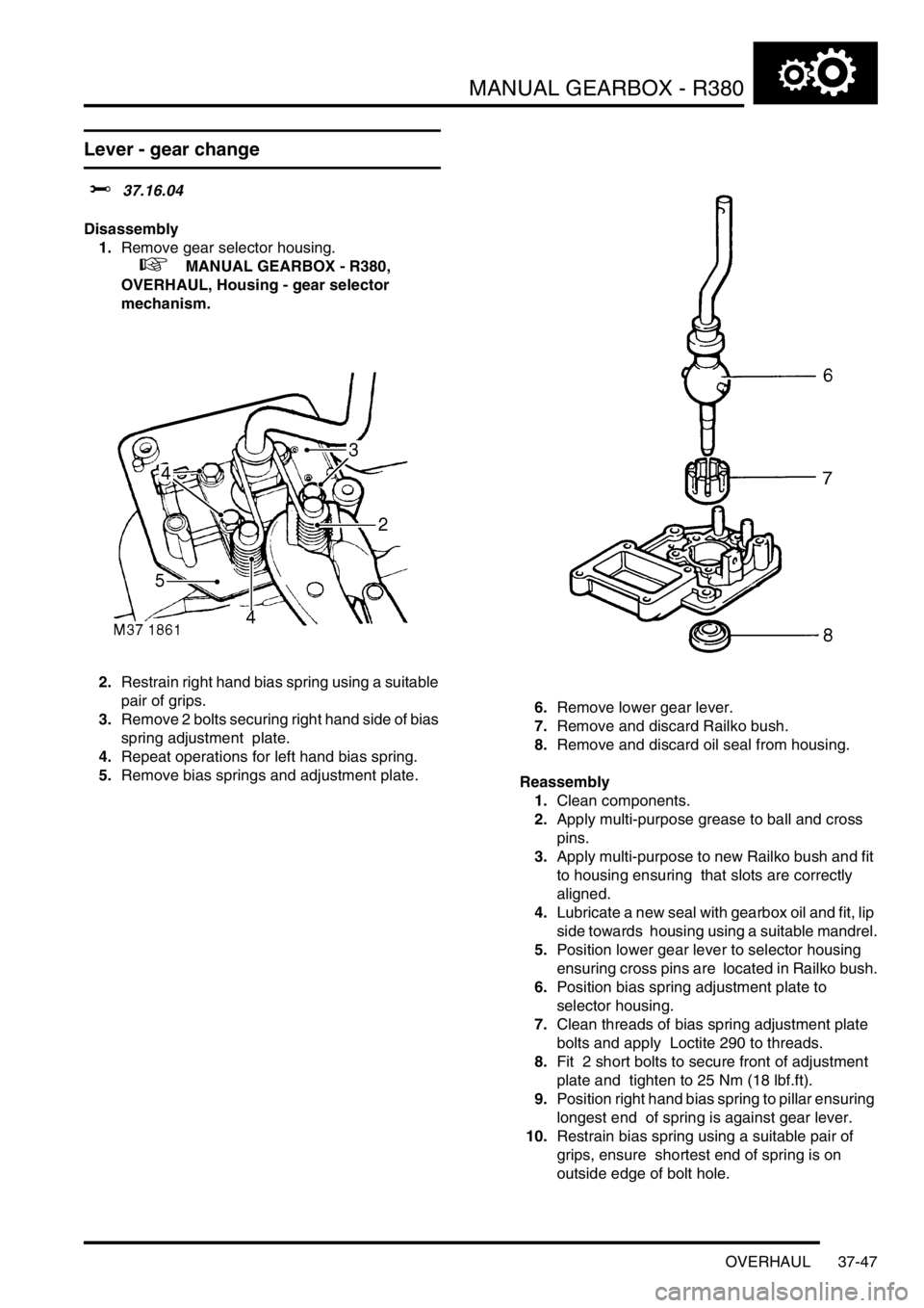
1.Remove gear selector housing.
+ MANUAL GEARBOX - R380,
OVERHAUL, Housing - gear selector
mechanism.
2.Restrain right hand bias spring using a suitable
pair of grips.
3.Remove 2 bolts securing right hand side of bias
spring adjustment plate.
4.Repeat operations for left hand bias spring.
5.Remove bias springs and adjustment plate.6.Remove lower gear lever.
7.Remove and discard Railko bush.
8.Remove and discard oil seal from housing.
Reassembly
1.Clean components.
2.Apply multi-purpose grease to ball and cross
pins.
3.Apply multi-purpose to new Railko bush and fit
to housing ensuring that slots are correctly
aligned.
4.Lubricate a new seal with gearbox oil and fit, lip
side towards housing using a suitable mandrel.
5.Position lower gear lever to selector housing
ensuring cross pins are located in Railko bush.
6.Position bias spring adjustment plate to
selector housing.
7.Clean threads of bias spring adjustment plate
bolts and apply Loctite 290 to threads.
8.Fit 2 short bolts to secure front of adjustment
plate and tighten to 25 Nm (18 lbf.ft).
9.Position right hand bias spring to pillar ensuring
longest end of spring is against gear lever.
10.Restrain bias spring using a suitable pair of
grips, ensure shortest end of spring is on
outside edge of bolt hole.
Page 763 of 1672
TRANSFER BOX - LT230SE
41-30 REPAIRS
Gasket - rear cover plate
$% 41.20.30
Remove
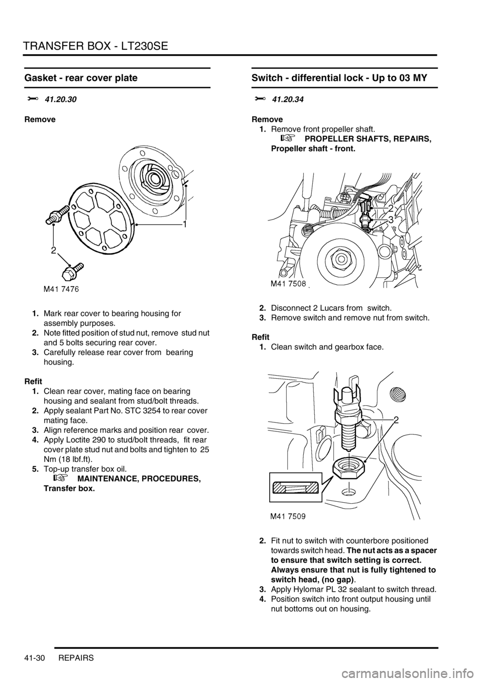
1.Mark rear cover to bearing housing for
assembly purposes.
2.Note fitted position of stud nut, remove stud nut
and 5 bolts securing rear cover.
3.Carefully release rear cover from bearing
housing.
Refit
1.Clean rear cover, mating face on bearing
housing and sealant from stud/bolt threads.
2.Apply sealant Part No. STC 3254 to rear cover
mating face.
3.Align reference marks and position rear cover.
4.Apply Loctite 290 to stud/bolt threads, fit rear
cover plate stud nut and bolts and tighten to 25
Nm (18 lbf.ft).
5.Top-up transfer box oil.
+ MAINTENANCE, PROCEDURES,
Transfer box.
Switch - differential lock - Up to 03 MY
$% 41.20.34
Remove
1.Remove front propeller shaft.
+ PROPELLER SHAFTS, REPAIRS,
Propeller shaft - front.
2.Disconnect 2 Lucars from switch.
3.Remove switch and remove nut from switch.
Refit
1.Clean switch and gearbox face.
2.Fit nut to switch with counterbore positioned
towards switch head. The nut acts as a spacer
to ensure that switch setting is correct.
Always ensure that nut is fully tightened to
switch head, (no gap).
3.Apply Hylomar PL 32 sealant to switch thread.
4.Position switch into front output housing until
nut bottoms out on housing.
Page 785 of 1672
TRANSFER BOX - LT230SE
41-52 OVERHAUL
Refit
1.Clean differential components.
2.Lubricate components with gearbox oil.
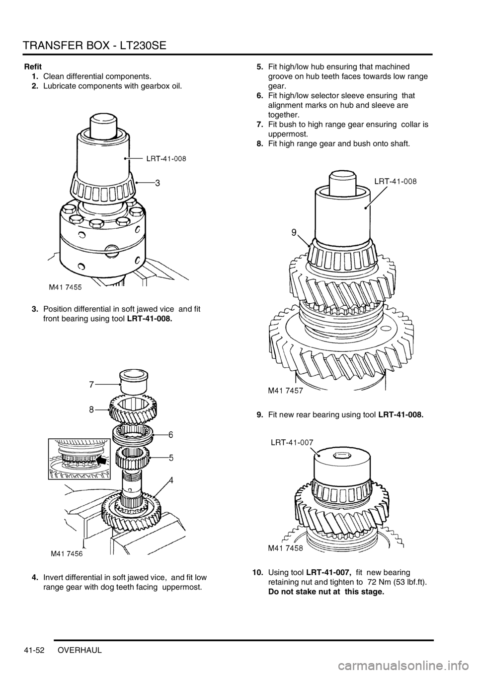
3.Position differential in soft jawed vice and fit
front bearing using tool LRT-41-008.
4.Invert differential in soft jawed vice, and fit low
range gear with dog teeth facing uppermost. 5.Fit high/low hub ensuring that machined
groove on hub teeth faces towards low range
gear.
6.Fit high/low selector sleeve ensuring that
alignment marks on hub and sleeve are
together.
7.Fit bush to high range gear ensuring collar is
uppermost.
8.Fit high range gear and bush onto shaft.
9.Fit new rear bearing using tool LRT-41-008.
10.Using tool LRT-41-007, fit new bearing
retaining nut and tighten to 72 Nm (53 lbf.ft).
Do not stake nut at this stage.
Page 788 of 1672
TRANSFER BOX - LT230SE
OVERHAUL 41-55
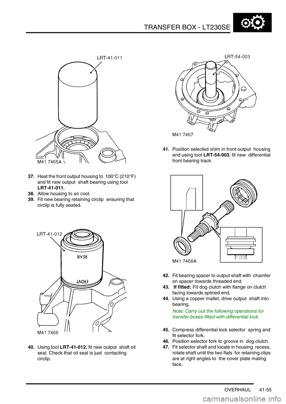
37.Heat the front output housing to 100°C (210°F)
and fit new output shaft bearing using tool
LRT-41-011.
38.Allow housing to air cool.
39.Fit new bearing retaining circlip ensuring that
circlip is fully seated.
40.Using tool LRT-41-012, fit new output shaft oil
seal. Check that oil seal is just contacting
circlip. 41.Position selected shim in front output housing
and using tool LRT-54-003, fit new differential
front bearing track.
42.Fit bearing spacer to output shaft with chamfer
on spacer towards threaded end.
43. If fitted: Fit dog clutch with flange on clutch
facing towards splined end.
44.Using a copper mallet, drive output shaft into
bearing.
Note: Carry out the following operations for
transfer boxes fitted with differential lock.
45.Compress differential lock selector spring and
fit selector fork.
46.Position selector fork to groove in dog clutch.
47.Fit selector shaft and locate in housing recess,
rotate shaft until the two flats for retaining clips
are at right angles to the cover plate mating
face.
Page 789 of 1672
TRANSFER BOX - LT230SE
41-56 OVERHAUL
48.Compress selector spring and fit retaining clips
at each end of spring.
CAUTION: Ensure ends of spring are fully
seated in recess of clips.
49.Fit detent ball and spring.
50.Apply Loctite 290 to threads of detent plug.
51.Fit and tighten detent plug, then loosen 2
complete turns.
52.Fit new 'O' ring to differential lock selector
housing.
53.Fit selector housing, ensure selector finger is
located in shaft recess.
54.Apply Loctite 290 to threads of bolts, and
tighten selector housing bolts to 25 Nm (18
lbf.ft).
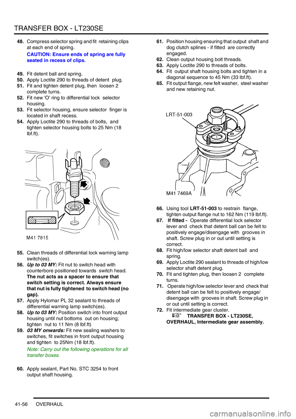
55.Clean threads of differential lock warning lamp
switch(es).
56.Up to 03 MY: Fit nut to switch head with
counterbore positioned towards switch head.
The nut acts as a spacer to ensure that
switch setting is correct. Always ensure
that nut is fully tightened to switch head (no
gap).
57.Apply Hylomar PL 32 sealant to threads of
differential warning lamp switch(es).
58.Up to 03 MY: Position switch into front output
housing until nut bottoms out on housing;
tighten nut to 11 Nm (8 lbf.ft)
59.03 MY onwards: Fit new sealing washers to
switches, fit switches in front output housing
and tighten to 25Nm (18 lbf.ft).
Note: Carry out the following operations for all
transfer boxes.
60.Apply sealant, Part No. STC 3254 to front
output shaft housing. 61.Position housing ensuring that output shaft and
dog clutch splines - if fitted are correctly
engaged.
62.Clean output housing bolt threads.
63.Apply Loctite 290 to threads of bolts.
64.Fit output shaft housing bolts and tighten in a
diagonal sequence to 45 Nm (33 lbf.ft).
65.Fit output flange, new felt washer, steel washer
and new retaining nut.
66.Using tool LRT-51-003 to restrain flange,
tighten output flange nut to 162 Nm (119 lbf.ft).
67. If fitted - Operate differential lock selector
lever and check that detent ball can be felt to
positively engage/disengage with grooves in
shaft. Screw plug in or out until setting is
correct.
68.Fit high/low selector shaft detent ball and
spring.
69.Apply Loctite 290 sealant to threads of high/low
selector shaft detent plug.
70.Fit and tighten plug, then loosen 2 complete
turns.
71. Operate high/low selector lever and check that
detent ball can be felt to positively engage/
disengage with grooves in shaft. Screw plug in
or out until setting is correct.
72.Fit intermediate gear cluster.
+ TRANSFER BOX - LT230SE,
OVERHAUL, Intermediate gear assembly.
Page 791 of 1672
TRANSFER BOX - LT230SE
41-58 OVERHAUL
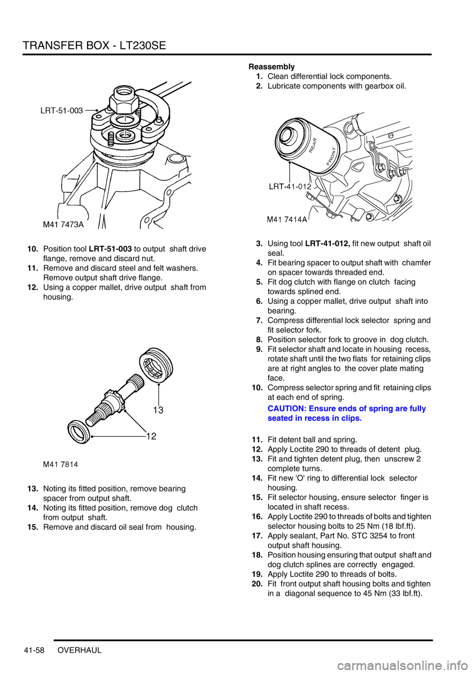
10.Position tool LRT-51-003 to output shaft drive
flange, remove and discard nut.
11.Remove and discard steel and felt washers.
Remove output shaft drive flange.
12.Using a copper mallet, drive output shaft from
housing.
13.Noting its fitted position, remove bearing
spacer from output shaft.
14.Noting its fitted position, remove dog clutch
from output shaft.
15.Remove and discard oil seal from housing. Reassembly
1.Clean differential lock components.
2.Lubricate components with gearbox oil.
3.Using tool LRT-41-012, fit new output shaft oil
seal.
4.Fit bearing spacer to output shaft with chamfer
on spacer towards threaded end.
5.Fit dog clutch with flange on clutch facing
towards splined end.
6.Using a copper mallet, drive output shaft into
bearing.
7.Compress differential lock selector spring and
fit selector fork.
8.Position selector fork to groove in dog clutch.
9.Fit selector shaft and locate in housing recess,
rotate shaft until the two flats for retaining clips
are at right angles to the cover plate mating
face.
10.Compress selector spring and fit retaining clips
at each end of spring.
CAUTION: Ensure ends of spring are fully
seated in recess in clips.
11.Fit detent ball and spring.
12.Apply Loctite 290 to threads of detent plug.
13.Fit and tighten detent plug, then unscrew 2
complete turns.
14.Fit new 'O' ring to differential lock selector
housing.
15.Fit selector housing, ensure selector finger is
located in shaft recess.
16.Apply Loctite 290 to threads of bolts and tighten
selector housing bolts to 25 Nm (18 lbf.ft).
17.Apply sealant, Part No. STC 3254 to front
output shaft housing.
18.Position housing ensuring that output shaft and
dog clutch splines are correctly engaged.
19.Apply Loctite 290 to threads of bolts.
20.Fit front output shaft housing bolts and tighten
in a diagonal sequence to 45 Nm (33 lbf.ft).
Page 792 of 1672
TRANSFER BOX - LT230SE
OVERHAUL 41-59
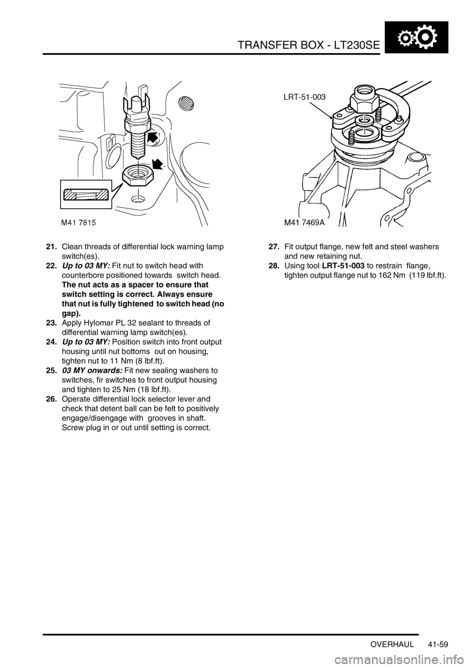
21.Clean threads of differential lock warning lamp
switch(es).
22.Up to 03 MY: Fit nut to switch head with
counterbore positioned towards switch head.
The nut acts as a spacer to ensure that
switch setting is correct. Always ensure
that nut is fully tightened to switch head (no
gap).
23.Apply Hylomar PL 32 sealant to threads of
differential warning lamp switch(es).
24.Up to 03 MY: Position switch into front output
housing until nut bottoms out on housing,
tighten nut to 11 Nm (8 lbf.ft).
25.03 MY onwards: Fit new sealing washers to
switches, fir switches to front output housing
and tighten to 25 Nm (18 lbf.ft).
26.Operate differential lock selector lever and
check that detent ball can be felt to positively
engage/disengage with grooves in shaft.
Screw plug in or out until setting is correct.27.Fit output flange, new felt and steel washers
and new retaining nut.
28.Using tool LRT-51-003 to restrain flange,
tighten output flange nut to 162 Nm (119 lbf.ft).
Page 796 of 1672
TRANSFER BOX - LT230SE
OVERHAUL 41-63
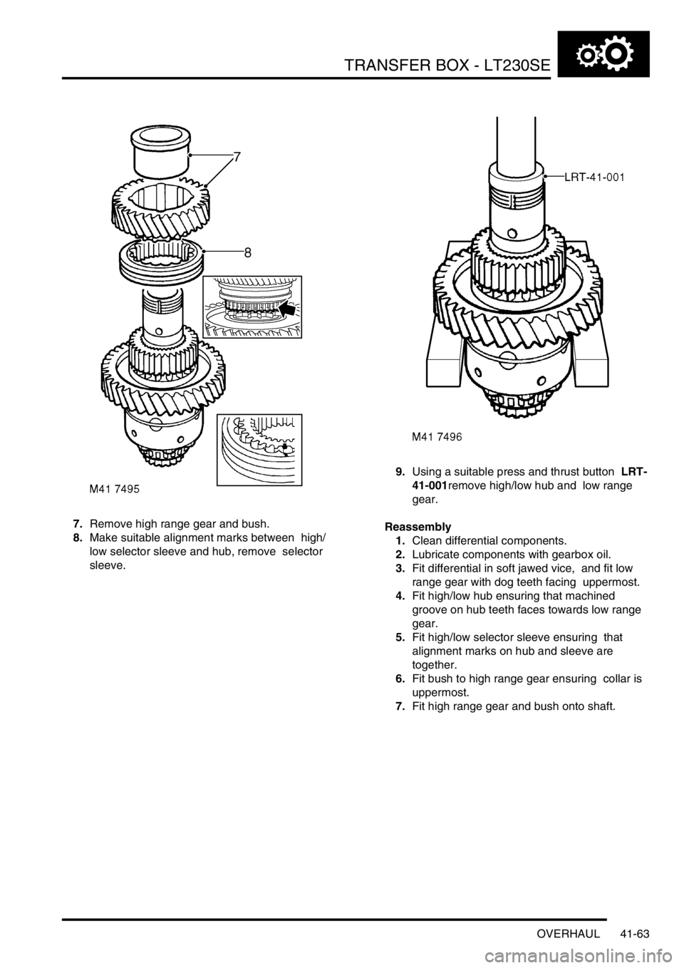
7.Remove high range gear and bush.
8.Make suitable alignment marks between high/
low selector sleeve and hub, remove selector
sleeve. 9.Using a suitable press and thrust button LRT-
41-001remove high/low hub and low range
gear.
Reassembly
1.Clean differential components.
2.Lubricate components with gearbox oil.
3.Fit differential in soft jawed vice, and fit low
range gear with dog teeth facing uppermost.
4.Fit high/low hub ensuring that machined
groove on hub teeth faces towards low range
gear.
5.Fit high/low selector sleeve ensuring that
alignment marks on hub and sleeve are
together.
6.Fit bush to high range gear ensuring collar is
uppermost.
7.Fit high range gear and bush onto shaft.
Page 815 of 1672

AUTOMATIC GEARBOX - ZF4HP22 - 24
44-18 DESCRIPTION AND OPERATION
With time, the components in a gearbox wear and the duration of the gear shifts tends to increase, which has an
adverse effect on the brake clutches. To counteract this, the EAT ECU applies a pressure adaptation to each shift.
To calculate the adaptations, the EAT ECU monitors the pressure modulation used, and time taken, for each shift. If
a subsequent shift of the same type, in terms of throttle position and engine speed, has a longer duration, the EAT
ECU stores an adaptation for that type of shift in a volatile memory. The adaptation is then included in future pressure
calculations for that type of shift, to restore shift duration to the nominal.
Kickdown
The EAT ECU monitors the input of the throttle position sensor to determine when kickdown is required. When it
detects a kickdown situation, the EAT ECU immediately initiates a down shift provided the target gear will not cause
the engine speed limit to be exceeded.
Torque converter lock-up
The EAT ECU energises the lock-up solenoid valve to engage the lock-up clutch. Lock-up clutch operation is
dependent on throttle position, engine speed, operating mode and the range selected on the transfer box.
High range
Unique lock-up maps, similar to the shift maps, are incorporated in the economy and sport modes for all forward gears.
Engagement and disengagement of the lock-up clutch is dependent on throttle position and engine speed.
Low range
To enhance off road control, particularly when manoeuvring at low speeds, torque converter lock-up does not occur
when there is any degree of throttle opening. When the throttle is closed above a preset engine speed, the lock-up
clutch engages to provide maximum engine braking.
Increased load/reduced torque compensation
To aid performance and driveability in the high range economy mode, the EAT ECU has three adaptive shift and lock-
up maps. These maps delay upshifts and torque converter lock-up similar to the sport mode if the inputs from the
engine indicate:
lA sustained high load on the engine, such as occurs when the vehicle is ascending a steep gradient or towing a
trailer.
lA lower than normal engine torque, such as occurs at altitude or high ambient temperatures.
The EAT ECU monitors the engine inputs and selects the most appropriate adaptive map for the prevailing conditions.
Diagnostics
While the ignition is on, the EAT ECU diagnoses the system for faults. The extent of the diagnostic capability at any
particular time depends on the prevailing operating conditions, e.g. it is not possible to check torque converter lock-
up while the vehicle is stationary, or to check for a short circuit to earth if the circuit concerned is already at a low
potential.
If a fault is detected, the EAT ECU immediately stores a fault code and the values of three operating parameters
associated with the fault. Depending on the fault, there are four possible effects:
lThe fault has little effect on gearbox operation or vehicle emissions. The driver will probably not notice any
change and the warning lamps remain extinguished.
lThe fault has little effect on gearbox operation but may effect vehicle emissions. On NAS vehicles, if the fault is
detected on a second consecutive drive cycle, the MIL illuminates.
lAll gears are available but kickdown does not function. The sport and manual warning lamps flash. The MIL
remains extinguished.
lLimp home mode is selected and vehicle performance is greatly reduced. The sport and manual warning lamps
flash. In all markets, if the fault is detected on a second consecutive drive cycle, the MIL illuminates.
Page 843 of 1672
AUTOMATIC GEARBOX - ZF4HP22 - 24
44-46 REPAIRS
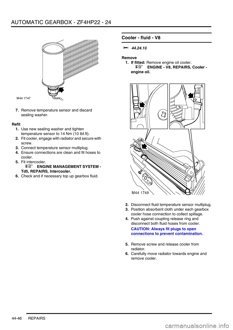
7.Remove temperature sensor and discard
sealing washer.
Refit
1.Use new sealing washer and tighten
temperature sensor to 14 Nm (10 lbf.ft).
2.Fit cooler, engage with radiator and secure with
screw.
3.Connect temperature sensor multiplug.
4.Ensure connections are clean and fit hoses to
cooler.
5.Fit intercooler.
+ ENGINE MANAGEMENT SYSTEM -
Td5, REPAIRS, Intercooler.
6.Check and if necessary top up gearbox fluid.
Cooler - fluid - V8
$% 44.24.10
Remove
1. If fitted: Remove engine oil cooler.
+ ENGINE - V8, REPAIRS, Cooler -
engine oil.
2.Disconnect fluid temperature sensor multiplug.
3.Position absorbent cloth under each gearbox
cooler hose connection to collect spillage.
4.Push against coupling release ring and
disconnect both fluid hoses from cooler.
CAUTION: Always fit plugs to open
connections to prevent contamination.
5.Remove screw and release cooler from
radiator.
6.Carefully move radiator towards engine and
remove cooler.