tow LAND ROVER DISCOVERY 2002 Repair Manual
[x] Cancel search | Manufacturer: LAND ROVER, Model Year: 2002, Model line: DISCOVERY, Model: LAND ROVER DISCOVERY 2002Pages: 1672, PDF Size: 46.1 MB
Page 848 of 1672

AUTOMATIC GEARBOX - ZF4HP22 - 24
REPAIRS 44-51
Lock-up solenoid valve (MV 3)
$% 44.15.35
Remove
1.Remove valve body assembly.
+ AUTOMATIC GEARBOX - ZF4HP22
- 24, REPAIRS, Valve body assembly.
2.Disconnect multiplug from lock-up solenoid
valve and release harness from clip.
3.Remove Torx screw and retaining fork securing
solenoid valve to valve body.
4.Remove solenoid valve from valve body.
Refit
1.Clean lock-up solenoid valve with lint free cloth.
2.Position solenoid valve in valve body.
3.Position retaining fork, fit and tighten Torx
screw to 8 Nm (6 lbf.ft).
4.Connect multiplug to lock-up solenoid valve
and secure harness in clip.
5.Fit valve body assembly.
+ AUTOMATIC GEARBOX - ZF4HP22
- 24, REPAIRS, Valve body assembly.
Solenoids - shift control valves (MV 1 &
2)
$% 44.15.45
Remove
1.Remove valve body assembly.
+ AUTOMATIC GEARBOX - ZF4HP22
- 24, REPAIRS, Valve body assembly.
2.Remove 3 Torx screws securing lock-up
solenoid valve assembly to valve body and
move solenoid aside.
NOTE: This is to gain access to remove Torx
screw and MV2 shift control valve.
3.Note their fitted position and disconnect
multiplugs from shift control valves MV 1 and
MV 2.
4.Remove Torx screw and retaining fork securing
MV2 shift control solenoid valve to valve body.
Note that the tag on the retaining fork faces
towards the valve body.
5.Remove shift control valve from valve body.
M44 1354A
2
3
4
M44 13521
M44 1353A
Page 873 of 1672
REAR AXLE
51-14 OVERHAUL
47.Tighten bearing cap bolts to 90 Nm (66.5 lbf.ft).
48.Secure adjusting nuts with new roll pins.
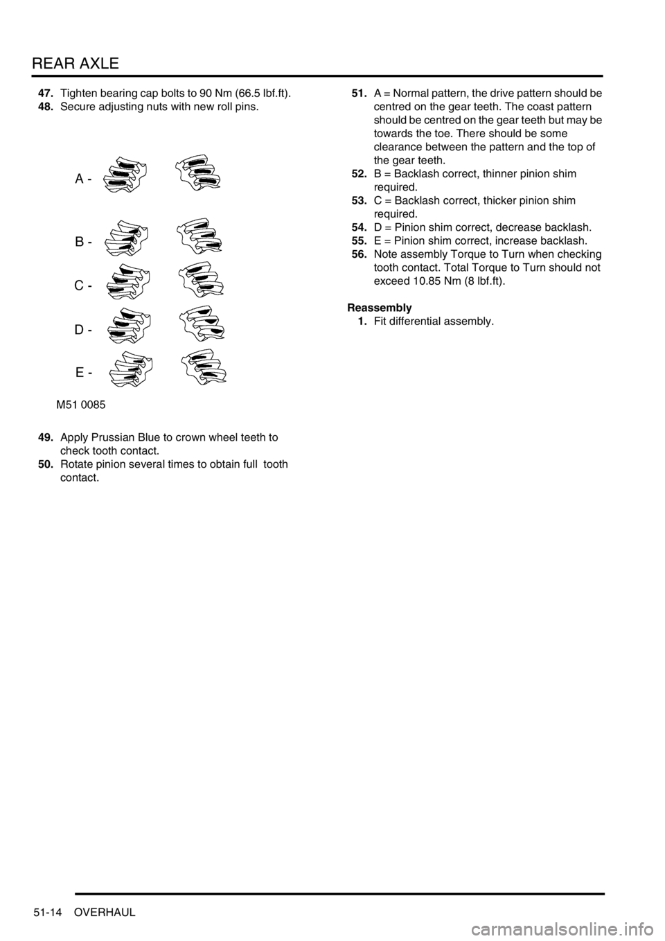
49.Apply Prussian Blue to crown wheel teeth to
check tooth contact.
50.Rotate pinion several times to obtain full tooth
contact.51.A = Normal pattern, the drive pattern should be
centred on the gear teeth. The coast pattern
should be centred on the gear teeth but may be
towards the toe. There should be some
clearance between the pattern and the top of
the gear teeth.
52.B = Backlash correct, thinner pinion shim
required.
53.C = Backlash correct, thicker pinion shim
required.
54.D = Pinion shim correct, decrease backlash.
55.E = Pinion shim correct, increase backlash.
56.Note assembly Torque to Turn when checking
tooth contact. Total Torque to Turn should not
exceed 10.85 Nm (8 lbf.ft).
Reassembly
1.Fit differential assembly.
Page 892 of 1672

STEERING
DESCRIPTION AND OPERATION 57-5
Description
General
The major steering components comprise an impact absorbing telescopic steering column, a Power Assisted Steering
(PAS) box, a PAS pump, and fluid reservoir. Hydraulic fluid from the fluid reservoir is filtered and then supplied
through the suction line to the inlet on the PAS pump. The PAS pump supplies fluid to the steering box through a
pressure line routed above the front cross member. Fluid returns to the reservoir along the same route through a
return line. On LH drive vehicles the pipe route above the front cross member is still used, the length of pipe acting
as an oil cooler.
To minimise driver's injury in the event of an accident the steering system has a number of safety features including
a collapsible steering column. An additional safety feature is an air bag located in the steering wheel.
+ RESTRAINT SYSTEMS, DESCRIPTION AND OPERATION, Description - SRS.
Steering column assembly and intermediate shaft
The steering column central shaft comprises of two shafts, the upper shaft is splined to accept the steering wheel and
located in bearings in the column tube. A universal joint is located on the bottom of the upper shaft, the joint allows
for angular movement between the upper and lower shafts. The lower shaft is made in two parts, the top section of
the lower shaft is located outside of the lower section. The two sections of the lower shaft are connected by two nylon
injection moulded shear pins. The lower shaft goes through a lower bearing attached to the bulkhead, the lower shaft
is connected by a universal joint to the intermediate shaft in the engine compartment.
Steering column
An upper column tube provides for the location of the steering lock and ignition switch and also the steering switch
gear and a rotary coupler. The rotary coupler provides the electrical connection for the steering wheel mounted airbag,
switches and horn. The upper mounting bracket has two slots, a slotted metal bracket is held in each slot by four resin
shear pins.
The column is mounted on four captive studs which are located on a column mounting bracket. The captive studs
pass through the metal brackets, locknuts secure the steering column to the bulkhead. The two lower mountings are
fixed and cannot move when loads are applied to them. The upper mounting is designed to disengage or deform when
a load is applied, allowing the column to collapse in the event of an accident. The steering column must be replaced
as a complete assembly if necessary.
When an axial load is applied to the upper column tube, energy absorption is achieved by the following mechanism:
lthe mounting bracket deforms,
lthe resin shear pins holding the slotted metal brackets shear,
lthe top mounting bracket slides out of the slotted metal brackets.
The slotted metal brackets remain on the captive studs on the bulkhead. If the column mounting moves, injection
moulded shear pins retaining the two sections of the lower column shaft will shear. This allows the two sections of the
lower shaft to 'telescope' together.
In the event of a collision where the steering box itself moves, two universal joints in the column allow the intermediate
shaft to articulate, minimising movement of the column towards the driver. If movement continues energy absorption
is achieved by the following mechanism:
lthe decouple joint in the intermediate shaft will disengage,
lthe lower section of the steering column shaft will move through the lower bearing,
lthe injection moulded shear pins retaining the two sections of the lower column shaft will shear.
This allows the two sections of the lower shaft to 'telescope' together reducing further column intrusion. Protection to
the drivers face and upper torso is provided by an SRS airbag module located in the centre of the steering wheel.
+ RESTRAINT SYSTEMS, DESCRIPTION AND OPERATION, Description - SRS.
Page 900 of 1672
STEERING
DESCRIPTION AND OPERATION 57-13
The PAS pump is a roller vane type and has an internal pressure regulator and flow control valve. The roller vanes
can move in slots in the pumps rotor and are moved outwards by centrifugal force as the pump rotates. The pump
rotor rotates in the pump housing, the internal shape of the housing forms a 'cam' shape. Due to the 'cam' shape the
volume of the housing decreases between the inlet and outlet ports.
As the pump rotor rotates towards the pump inlet the volume between the roller vanes and the pump housing
increases, this action causes a depression in the chamber between the pump roller vanes and the housing. As the
rotation continues the chamber is opened to the pump inlet, and the depression in the chamber causes fluid to be
drawn in. The roller vanes continue past the inlet port, closing off the inlet port and trapping the fluid in the chamber
between the rollers and the pump housing.
The internal 'cam' shape of the pump housing causes the rollers to move closer together as the pump rotor rotates
towards the outlet port. The reduced volume of the chamber between the roller vanes causes the fluid to become
pressurised. When the chamber is opened to the outlet port of the pump the fluid escapes at high pressure. The roller
vanes continue turning and go past the outlet port, closing off the chamber between the two roller vanes.
As rotation continues the inlet sequence begins again. The inlet and pressurisation/outlet sequences continue as the
pump rotates, and is repeated between each two roller vanes. The pump is a positive displacement type and the
potential pump output increases with engine (drive pulley) speed. The pressure relief and flow control valve regulates
flow/pressure by diverting fluid back to the pump inlet through internal recirculation passages in the pump body.
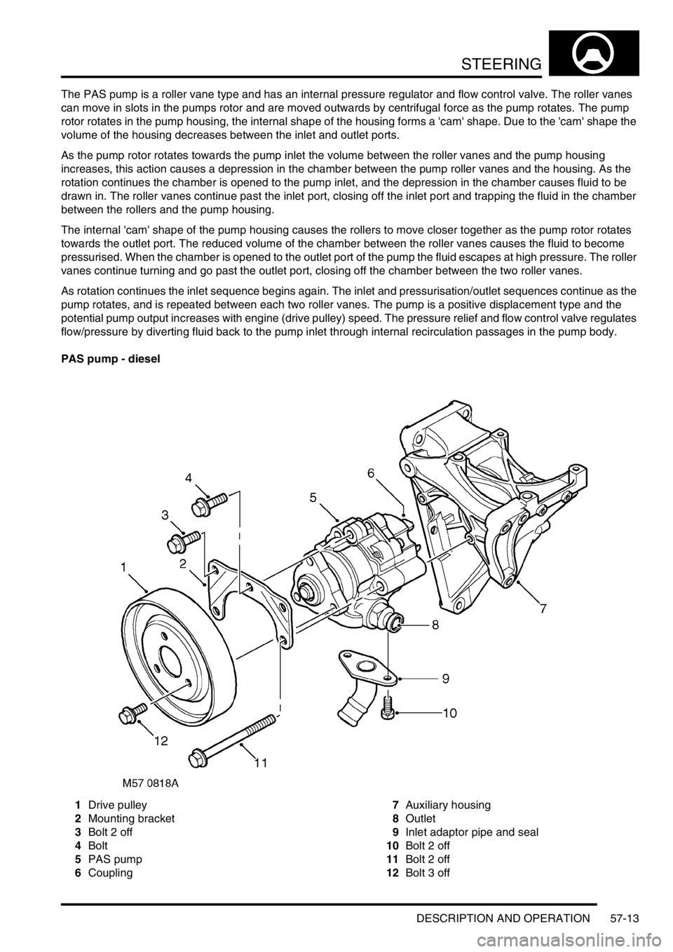
PAS pump - diesel
1Drive pulley
2Mounting bracket
3Bolt 2 off
4Bolt
5PAS pump
6Coupling7Auxiliary housing
8Outlet
9Inlet adaptor pipe and seal
10Bolt 2 off
11Bolt 2 off
12Bolt 3 off
Page 901 of 1672

STEERING
57-14 DESCRIPTION AND OPERATION
The PAS pump is located on the auxiliary housing, two bolts go through the PAS pump, mounting bracket and into
the auxiliary housing. One bolt also attaches the mounting bracket to the PAS pump, two bolts secure the mounting
bracket to the auxiliary housing. An inlet adaptor pipe with a seal is secured to the bottom of the pump with two bolts.
A drive pulley is attached to the pump drive shaft with three bolts, and is belt driven at a ratio of 1.35 crankshaft
revolutions to 1 of the drive pulley. A coupling on the rear of the PAS pump rotates the water pump impeller located
in the auxiliary housing. Fluid is supplied to the PAS pump inlet from the reservoir through a flexible hose at low
(suction) pressure. Fluid at high pressure from the PAS pump outlet is supplied to the rotary control valve on the
steering box.
The PAS pump is a roller vane type and has an internal pressure regulator and flow control valve. The roller vanes
can move in slots in the pumps rotor and are moved outwards by centrifugal force as the pump rotates. The pump
rotor rotates in the pump housing, the internal shape of the housing forms a 'cam' shape. Due to the 'cam' shape the
volume of the housing decreases between the inlet and outlet ports.
As the pump rotor rotates towards the pump inlet the volume between the roller vanes and the pump housing
increases, this action causes a depression in the chamber between the pump roller vanes and the housing. As the
rotation continues the chamber is opened to the pump inlet, and the depression in the chamber causes fluid to be
drawn in. The roller vanes continue past the inlet port, closing off the inlet port and trapping the fluid in the chamber
between the rollers and the pump housing.
The internal 'cam' shape of the pump housing causes the rollers to move closer together as the pump rotor rotates
towards the outlet port. The reduced volume of the chamber between the roller vanes causes the fluid to become
pressurised. When the chamber is opened to the outlet port of the pump the fluid escapes at high pressure. The roller
vanes continue turning and go past the outlet port, closing off the chamber between the two roller vanes.
As rotation continues the inlet sequence begins again. The inlet and pressurisation/outlet sequences continue as the
pump rotates, and is repeated between each two roller vanes. The pump is a positive displacement type and the
potential pump output increases with engine (drive pulley) speed. The pressure relief and flow control valve regulates
flow/pressure by diverting fluid back to the pump inlet through internal recirculation passages in the pump body.
Steering damper
The steering damper is located behind and just below the first cross member of the chassis. The ends of the steering
damper have steel 'eyes' welded on, rubber bushes are installed in each 'eye'. The steering damper is attached
between brackets on the chassis rail and the drag link. Each end of the steering damper is secured by a bolt and
locknut. The hydraulic damper absorbs shocks in the steering, caused by road wheel deflections when operating on
rough terrain.
Page 980 of 1672

FRONT SUSPENSION
REPAIRS 60-41
6.Remove 3 nuts securing ACE ECU and remove
ACE ECU.
Refit
1.Fit ACE ECU to bracket and secure with nuts.
2.Fit ECU's and bracket assembly to body and
secure with nuts.
3.Connect multiplugs to ACE ECU and SLABS
ECU.
4.Fit BCU.
+ BODY CONTROL UNIT, REPAIRS,
Body control unit (BCU).
5.If a replacement ACE ECU has been fitted, use
TestBook to calibrate ACE system.
Accelerometer - ACE - upper
$% 60.60.02
CAUTION: The accelerometer is an extremely
delicate component and can easily be rendered
unserviceable. Never use an accelerometer
which has been dropped or subjected to
mistreatment of any type.
Remove
1.Remove front stowage pocket.
+ INTERIOR TRIM COMPONENTS,
REPAIRS, Stowage pocket - front.
2.Disconnect multiplug from accelerometer.
3.Use LRT-60-014A to release clip and remove
accelerometer.
Refit
1.Using LRT-60-014A, fit accelerometer fully into
clip.
2.Connect accelerometer multiplug.
3.Fit front stowage pocket.
+ INTERIOR TRIM COMPONENTS,
REPAIRS, Stowage pocket - front.
4.If a replacement accelerometer has been fitted,
use TestBook to calibrate ACE system.
Page 1017 of 1672

REAR SUSPENSION
64-12 DESCRIPTION AND OPERATION
Description - SLS
General
The Self Levelling Suspension (SLS) system is an optional fitment and comprises an Electronic Control Unit (ECU),
air supply unit, two air springs and two height sensors. The SLS system only operates on the rear suspension and is
designed to keep the vehicle level to compensate for uneven loads or when towing. The system controls the gap
between the chassis and the rear axle to a tolerance of
± 0.5 mm (0.02 in). The ride height of the rear of the vehicle
can be controlled in three modes of operation; normal ride height, Off-Road Mode (ORM) and extended mode. A
transportation mode, initiated using TestBook, is also available for moving the vehicle on a trailer.
The system is controlled electronically by an ECU which is shared with the ABS system and known as the Self
Levelling and Anti-Lock Braking System (SLABS) ECU. The system operates by using an air supply unit to inflate or
deflate the air springs to maintain a constant ride height.
An accessory remote handset is available to remotely operate the SLS system to allow easier connection and
disconnection of trailers.
Two SLS system warning lamps are located in the instrument pack. The warning lamp in the bottom left corner of the
instrument pack is the SLS warning lamp. If a fault is detected in the system, the warning lamp will illuminate
continuously in an amber colour. The warning lamp also flashes in an amber colour when the remote handset is being
used. The second warning lamp, located in the top right of the instrument pack is the ORM warning lamp. When ORM
is selected the warning lamp is continuously illuminated in an amber colour. When the SLS is between standard ride
height and ORM or in extended mode, the warning lamp will flash. Standard ride height, measured between the tip of
the axle bump stop rubber and the axle, is 61.5 mm (2.42 in). ORM ride height, measured between the tip of axle
bump stop and the axle, is 100 mm (3.93 in).
A switch is located in the group of six switches on the fascia and is used to select the ORM. The switch is non-latching
and must be depressed for a minimum of 0.5 seconds to signal the ECU that ORM has been requested.
Page 1083 of 1672
BRAKES
70-38 REPAIRS
4.Using tool LRT-70-500, press caliper pistons
fully into bores. Ensure that displaced fluid
does not overflow from reservoir.
5.Fit brake pads with chamfer towards leading
edge of disc.
6.Lower caliper housing over pads.
7.Ensure flats on guide pins locate with lugs on
caliper housing. fit new pivot bolt and tighten to
30 Nm (22 lbf.ft).
8.Fit road wheel(s) and tighten nuts to 140 Nm
(103 lbf.ft).
9.Remove stand(s) and lower vehicle.
10.Depress brake several times to set pad to disc
clearance.
11.Check and top-up brake fluid.
Brake pads - rear
$% 70.40.10
WARNING: Brake pads must be renewed in axle
sets only, otherwise braking efficiency may be
impaired.
Remove
1.Raise rear of vehicle.
WARNING: Do not work on or under a
vehicle supported only by a jack. Always
support the vehicle on safety stands.
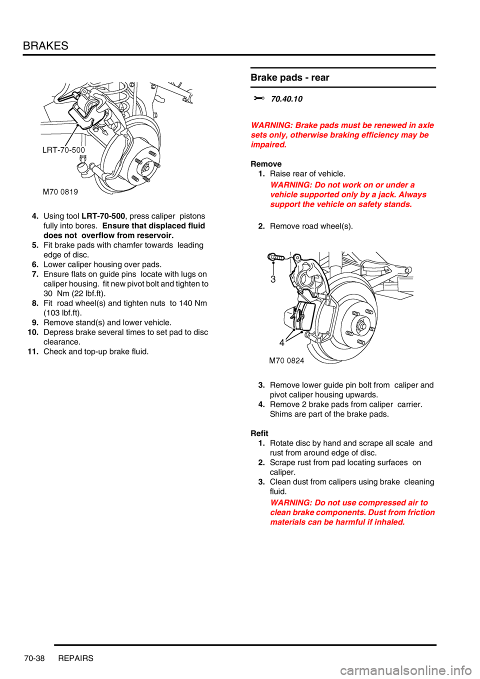
2.Remove road wheel(s).
3.Remove lower guide pin bolt from caliper and
pivot caliper housing upwards.
4.Remove 2 brake pads from caliper carrier.
Shims are part of the brake pads.
Refit
1.Rotate disc by hand and scrape all scale and
rust from around edge of disc.
2.Scrape rust from pad locating surfaces on
caliper.
3.Clean dust from calipers using brake cleaning
fluid.
WARNING: Do not use compressed air to
clean brake components. Dust from friction
materials can be harmful if inhaled.
Page 1173 of 1672
INTERIOR TRIM COMPONENTS
76-3-20 REPAIRS
Headlining
$% 76.64.15.21
Remove
1.Remove both 'D' post trim casings.
+ INTERIOR TRIM COMPONENTS,
REPAIRS, Trim casing - 'D' post.
2.Remove both 'B' post upper trim casings.
+ INTERIOR TRIM COMPONENTS,
REPAIRS, Trim casing - upper - 'B' post.
3.Release clips securing both 'A' post trim
casings.
4. Models with premium ICE: Disconnect
multiplugs from 'A' post speakers.
5.Remove both 'A' post trim casings.
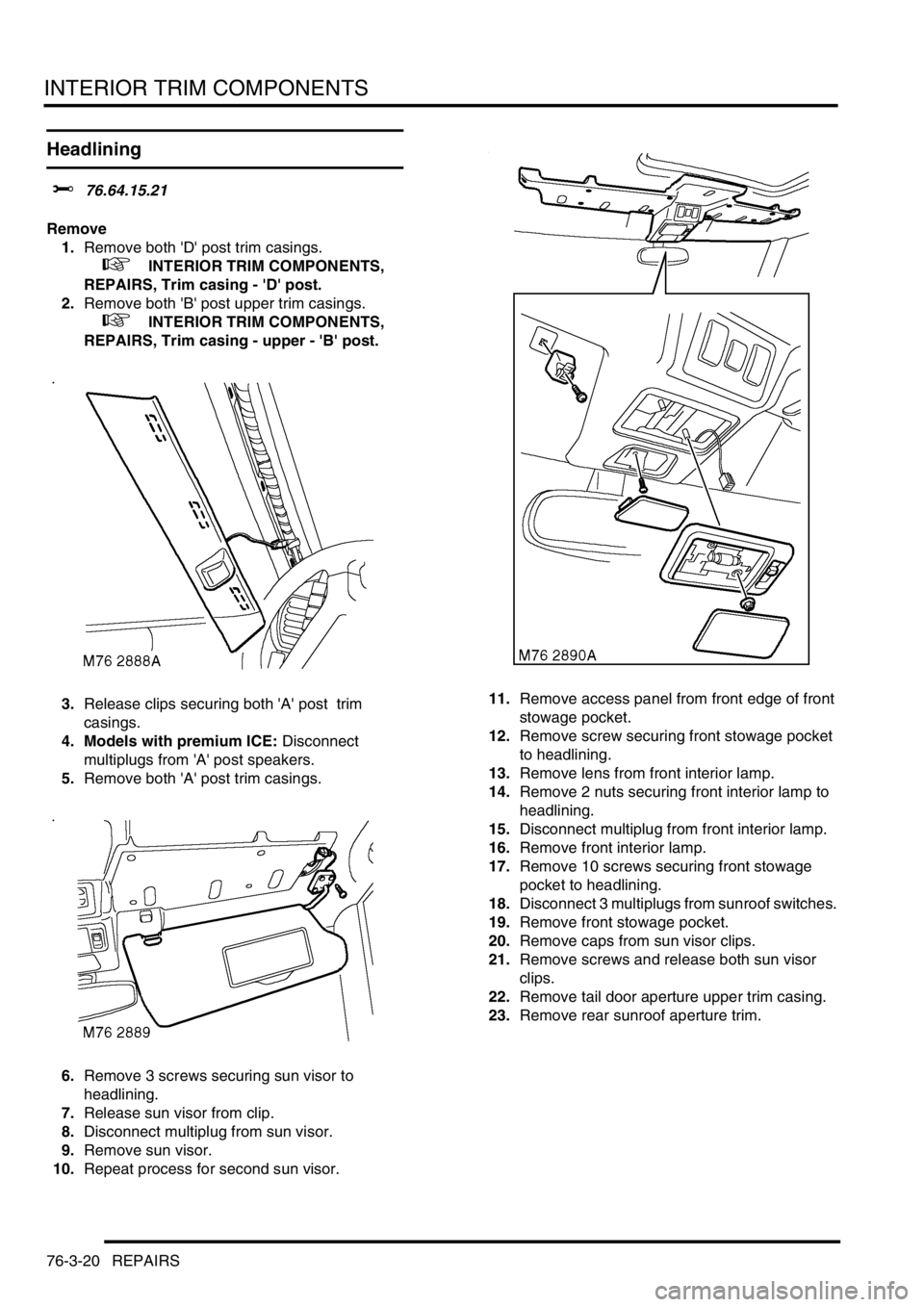
6.Remove 3 screws securing sun visor to
headlining.
7.Release sun visor from clip.
8.Disconnect multiplug from sun visor.
9.Remove sun visor.
10.Repeat process for second sun visor. 11.Remove access panel from front edge of front
stowage pocket.
12.Remove screw securing front stowage pocket
to headlining.
13.Remove lens from front interior lamp.
14.Remove 2 nuts securing front interior lamp to
headlining.
15.Disconnect multiplug from front interior lamp.
16.Remove front interior lamp.
17.Remove 10 screws securing front stowage
pocket to headlining.
18.Disconnect 3 multiplugs from sunroof switches.
19.Remove front stowage pocket.
20.Remove caps from sun visor clips.
21.Remove screws and release both sun visor
clips.
22.Remove tail door aperture upper trim casing.
23.Remove rear sunroof aperture trim.
Page 1175 of 1672
INTERIOR TRIM COMPONENTS
76-3-22 REPAIRS
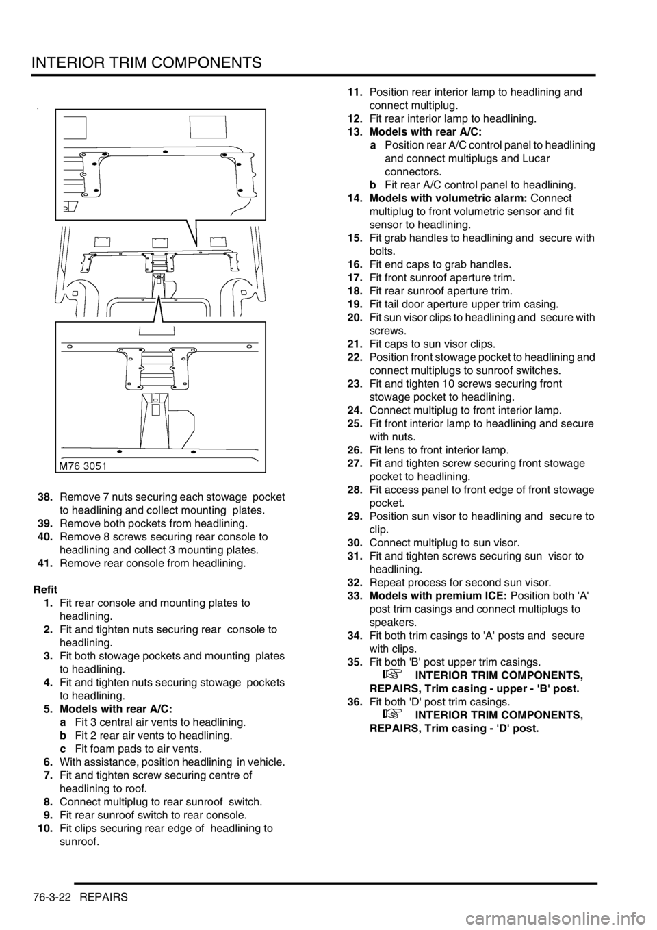
38.Remove 7 nuts securing each stowage pocket
to headlining and collect mounting plates.
39.Remove both pockets from headlining.
40.Remove 8 screws securing rear console to
headlining and collect 3 mounting plates.
41.Remove rear console from headlining.
Refit
1.Fit rear console and mounting plates to
headlining.
2.Fit and tighten nuts securing rear console to
headlining.
3.Fit both stowage pockets and mounting plates
to headlining.
4.Fit and tighten nuts securing stowage pockets
to headlining.
5. Models with rear A/C:
aFit 3 central air vents to headlining.
bFit 2 rear air vents to headlining.
cFit foam pads to air vents.
6.With assistance, position headlining in vehicle.
7.Fit and tighten screw securing centre of
headlining to roof.
8.Connect multiplug to rear sunroof switch.
9.Fit rear sunroof switch to rear console.
10.Fit clips securing rear edge of headlining to
sunroof. 11.Position rear interior lamp to headlining and
connect multiplug.
12.Fit rear interior lamp to headlining.
13. Models with rear A/C:
aPosition rear A/C control panel to headlining
and connect multiplugs and Lucar
connectors.
bFit rear A/C control panel to headlining.
14. Models with volumetric alarm: Connect
multiplug to front volumetric sensor and fit
sensor to headlining.
15.Fit grab handles to headlining and secure with
bolts.
16.Fit end caps to grab handles.
17.Fit front sunroof aperture trim.
18.Fit rear sunroof aperture trim.
19.Fit tail door aperture upper trim casing.
20.Fit sun visor clips to headlining and secure with
screws.
21.Fit caps to sun visor clips.
22.Position front stowage pocket to headlining and
connect multiplugs to sunroof switches.
23.Fit and tighten 10 screws securing front
stowage pocket to headlining.
24.Connect multiplug to front interior lamp.
25.Fit front interior lamp to headlining and secure
with nuts.
26.Fit lens to front interior lamp.
27.Fit and tighten screw securing front stowage
pocket to headlining.
28.Fit access panel to front edge of front stowage
pocket.
29.Position sun visor to headlining and secure to
clip.
30.Connect multiplug to sun visor.
31.Fit and tighten screws securing sun visor to
headlining.
32.Repeat process for second sun visor.
33. Models with premium ICE: Position both 'A'
post trim casings and connect multiplugs to
speakers.
34.Fit both trim casings to 'A' posts and secure
with clips.
35.Fit both 'B' post upper trim casings.
+ INTERIOR TRIM COMPONENTS,
REPAIRS, Trim casing - upper - 'B' post.
36.Fit both 'D' post trim casings.
+ INTERIOR TRIM COMPONENTS,
REPAIRS, Trim casing - 'D' post.