LAND ROVER DISCOVERY 2002 Workshop Manual
Manufacturer: LAND ROVER, Model Year: 2002, Model line: DISCOVERY, Model: LAND ROVER DISCOVERY 2002Pages: 1672, PDF Size: 46.1 MB
Page 361 of 1672
EMISSION CONTROL - V8
17-2-24 DESCRIPTION AND OPERATION
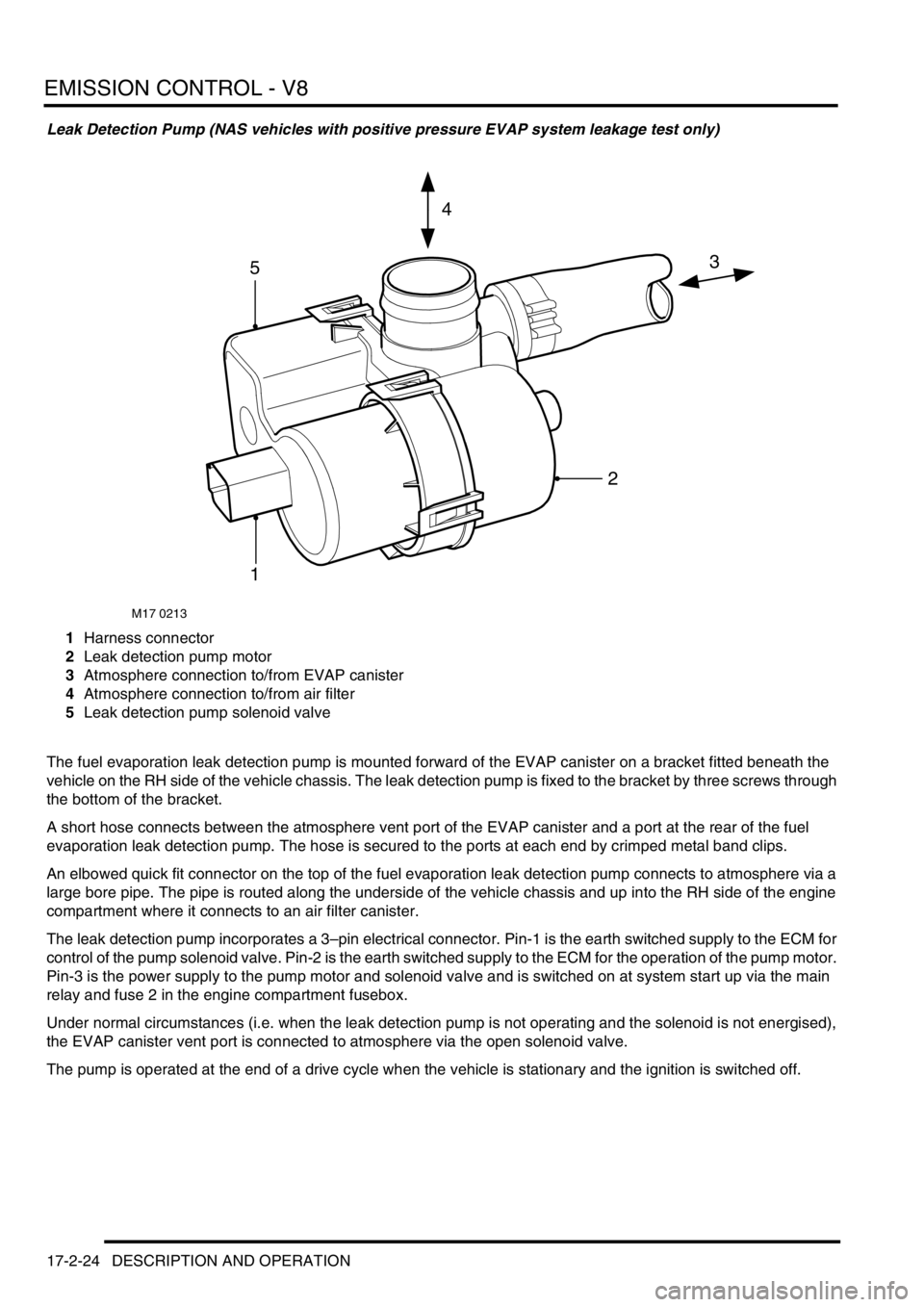
Leak Detection Pump (NAS vehicles with positive pressure EVAP system leakage test only)
1Harness connector
2Leak detection pump motor
3Atmosphere connection to/from EVAP canister
4Atmosphere connection to/from air filter
5Leak detection pump solenoid valve
The fuel evaporation leak detection pump is mounted forward of the EVAP canister on a bracket fitted beneath the
vehicle on the RH side of the vehicle chassis. The leak detection pump is fixed to the bracket by three screws through
the bottom of the bracket.
A short hose connects between the atmosphere vent port of the EVAP canister and a port at the rear of the fuel
evaporation leak detection pump. The hose is secured to the ports at each end by crimped metal band clips.
An elbowed quick fit connector on the top of the fuel evaporation leak detection pump connects to atmosphere via a
large bore pipe. The pipe is routed along the underside of the vehicle chassis and up into the RH side of the engine
compartment where it connects to an air filter canister.
The leak detection pump incorporates a 3–pin electrical connector. Pin-1 is the earth switched supply to the ECM for
control of the pump solenoid valve. Pin-2 is the earth switched supply to the ECM for the operation of the pump motor.
Pin-3 is the power supply to the pump motor and solenoid valve and is switched on at system start up via the main
relay and fuse 2 in the engine compartment fusebox.
Under normal circumstances (i.e. when the leak detection pump is not operating and the solenoid is not energised),
the EVAP canister vent port is connected to atmosphere via the open solenoid valve.
The pump is operated at the end of a drive cycle when the vehicle is stationary and the ignition is switched off.
M17 0213
3
4
5
1
2
Page 362 of 1672
EMISSION CONTROL - V8
DESCRIPTION AND OPERATION 17-2-25
The leak detection pump module contains an integral air by-pass circuit with restrictor (reference-leak orifice) which
is used for providing a reference value for the leak detection test. The restrictor corresponds to an air leak equivalent
to 0.5 mm (0.02 in) diameter. With the solenoid valve open and the purge valve closed, the pump forces pressurised
air through the orifice while the current drawn by the leak detection pump motor is monitored to obtain the reference
value. The orifice must be kept free from contamination, otherwise the reference restriction may appear less than for
a 0.5 mm leak and consequently adversely affect the diagnostic results.
During the leakage test, the solenoid valve is energised, closing the atmosphere vent line between the EVAP canister
and atmosphere and opening a path to the pressurised air supplied from the leak detection pump motor. Air is pumped
into the EVAP system, while the current drawn by the pump motor is monitored. The current drawn during the leakage
test is compared against the value obtained during the reference check, to determine if an EVAP system leak is
present.
The fuel leak detection pump is powered from a 12V supply and operates at a working pressure of 3 kPa.
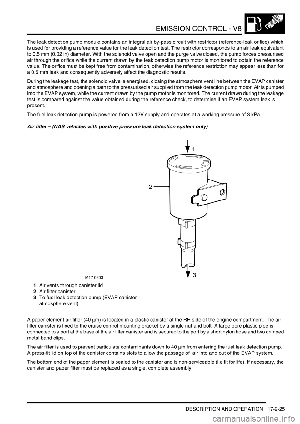
Air filter – (NAS vehicles with positive pressure leak detection system only)
1Air vents through canister lid
2Air filter canister
3To fuel leak detection pump (EVAP canister
atmosphere vent)
A paper element air filter (40
µm) is located in a plastic canister at the RH side of the engine compartment. The air
filter canister is fixed to the cruise control mounting bracket by a single nut and bolt. A large bore plastic pipe is
connected to a port at the base of the air filter canister and is secured to the port by a short nylon hose and two crimped
metal band clips.
The air filter is used to prevent particulate contaminants down to 40
µm from entering the fuel leak detection pump.
A press-fit lid on top of the canister contains slots to allow the passage of air into and out of the EVAP system.
The bottom end of the paper element is sealed to the canister and is non-serviceable (i.e fit for life). If necessary, the
canister and paper filter must be replaced as a single, complete assembly.
M17 0203
2
1
3
Page 363 of 1672

EMISSION CONTROL - V8
17-2-26 DESCRIPTION AND OPERATION
Secondary air injection system
The secondary air injection (SAI) system comprises the following components:
lSecondary air injection pump
lSAI vacuum solenoid valve
lSAI control valves (2 off, 1 for each bank of cylinders)
lSAI pump relay
lVacuum reservoir
lVacuum harness and pipes
The secondary air injection system is used to limit the emission of carbon monoxide (CO) and hydrocarbons (HCs)
that are prevalent in the exhaust during cold starting of a spark ignition engine. The concentration of hydrocarbons
experienced during cold starting at low temperatures are particularly high until the engine and catalytic converter
reach normal operating temperature. The lower the cold start temperature, the greater the prevalence of
hydrocarbons emitted from the engine.
There are several reasons for the increase of HC emissions at low cold start temperatures, including the tendency for
fuel to be deposited on the cylinder walls, which is then displaced during the piston cycle and expunged during the
exhaust stroke. As the engine warms up through operation, the cylinder walls no longer retain a film of fuel and most
of the hydrocarbons will be burnt off during the combustion process.
The SAI pump is used to provide a supply of air into the exhaust ports in the cylinder head, onto the back of the
exhaust valves, during the cold start period. The hot unburnt fuel particles leaving the combustion chamber mix with
the air injected into the exhaust ports and immediately combust. This subsequent combustion of the unburnt and
partially burnt CO and HC particles help to reduce the emission of these pollutants from the exhaust system. The
additional heat generated in the exhaust manifold also provides rapid heating of the exhaust system catalytic
converters. The additional oxygen which is delivered to the catalytic converters also generate an exothermic reaction
which causes the catalytic converters to 'light off' quickly.
The catalytic converters only start to provide effective treatment of emission pollutants when they reach an operating
temperature of approximately 250
°C (482°F) and need to be between temperatures of 400°C (752°F) and 800°C
(1472
°F) for optimum efficiency. Consequently, the heat produced by the secondary air injection “afterburning”,
reduces the time delay before the catalysts reach an efficient operating temperature.
The engine control module (ECM) checks the engine coolant temperature when the engine is started, and if it is below
60º C (131
°F), the SAI pump is started. Secondary air injection will remain operational for a period controlled by the
ECM (76 seconds for NAS vehicles, 64 seconds for EU-3 vehicles). The SAI pump operation can be cut short due to
excessive engine speed or load.
Air from the SAI pump is supplied to the SAI control valves via pipework and an intermediate T-piece which splits the
air flow evenly to each bank.
At the same time the secondary air pump is started, the ECM operates a SAI vacuum solenoid valve, which opens to
allow vacuum from the reservoir to be applied to the vacuum operated SAI control valves on each side of the engine.
When the vacuum is applied to the SAI control valves, they open simultaneously to allow the air from the SAI pump
through to the exhaust ports. Secondary air is injected into the inner most exhaust ports on each bank.
When the ECM breaks the ground circuit to de-energise the SAI vacuum solenoid valve, the vacuum supply to the
SAI control valves is cut off and the valves close to prevent further air being injected into the exhaust manifold. At the
same time as the SAI vacuum solenoid valve is closed, the ECM opens the ground circuit to the SAI pump relay, to
stop the SAI pump.
A vacuum reservoir is included in the vacuum line between the intake manifold and the SAI vacuum solenoid valve.
This prevents changes in vacuum pressure from the intake manifold being passed on to cause fluctuations of the
secondary air injection solenoid valve. The vacuum reservoir contains a one way valve and ensures a constant
vacuum is available for the SAI vacuum solenoid valve operation. This is particularly important when the vehicle is at
high altitude.
Page 364 of 1672
EMISSION CONTROL - V8
DESCRIPTION AND OPERATION 17-2-27
The ECM connector and pins pertinent for secondary air injection are listed in the following table:
Secondary air injection system components
The secondary air injection (SAI) system components (NAS only) are described below:
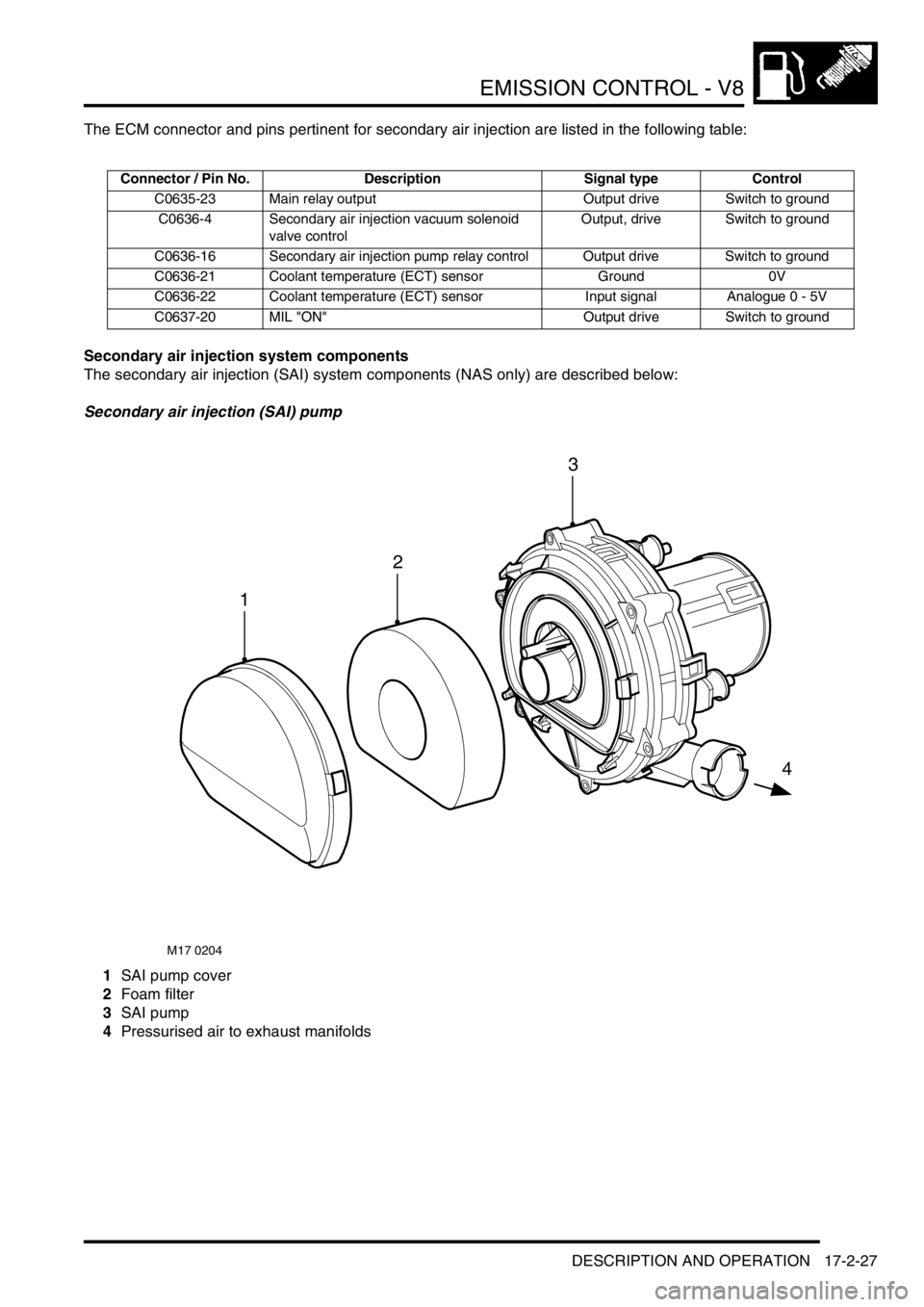
Secondary air injection (SAI) pump
1SAI pump cover
2Foam filter
3SAI pump
4Pressurised air to exhaust manifolds
Connector / Pin No. Description Signal type Control
C0635-23 Main relay output Output drive Switch to ground
C0636-4 Secondary air injection vacuum solenoid
valve controlOutput, drive Switch to ground
C0636-16 Secondary air injection pump relay control Output drive Switch to ground
C0636-21 Coolant temperature (ECT) sensor Ground 0V
C0636-22 Coolant temperature (ECT) sensor Input signal Analogue 0 - 5V
C0637-20 MIL "ON" Output drive Switch to ground
M17 0204
1
4
2
3
Page 365 of 1672

EMISSION CONTROL - V8
17-2-28 DESCRIPTION AND OPERATION
The SAI pump is attached to a bracket at the rear RH side of the engine compartment and is fixed to the bracket by
three studs and nuts. The pump is electrically powered from a 12V battery supply via a dedicated relay and supplies
approximately 35kg/hr of air when the vehicle is at idle in Neutral/Park on a start from 20
°C (68°F).
Air is drawn into the pump through vents in its front cover and is then passed through a foam filter to remove
particulates before air injection. The air is delivered to the exhaust manifold on each side of the engine through a
combination of plastic and metal pipes.
The air delivery pipe is a flexible plastic type, and is connected to the air pump outlet via a plastic quick-fit connector.
The other end of the flexible plastic pipe connects to the fixed metal pipework via a short rubber hose. The part of the
flexible plastic pipe which is most vulnerable to engine generated heat is protected by heat reflective sleeving. The
metal delivery pipe has a fabricated T-piece included where the pressurised air is split for delivery to each exhaust
manifold via the SAI control valves.
The pipes from the T-piece to each of the SAI control valves are approximately the same length, so that the pressure
and mass of the air delivered to each bank will be equal. The ends of the pipes are connected to the inlet port of each
SAI control valve through short rubber hose connections.
The T-piece is mounted at the rear of the engine (by the ignition coils) and features a welded mounting bracket which
is fixed to the engine by two studs and nuts.
The foam filter in the air intake of the SAI pump provides noise reduction and protects the pump from damage due to
particulate contamination. In addition, the pump is fitted on rubber mountings to help prevent noise which is generated
by pump operation from being transmitted through the vehicle body into the passenger compartment.
If the secondary air injection pump malfunctions, the following fault codes may be stored in the ECM diagnostic
memory, which can be retrieved using 'Testbook':
Secondary air injection (SAI) pump relay
The secondary air injection pump relay is located in the engine compartment fusebox. The engine control module
(ECM) is used to control the operation of the SAI pump via the SAI pump relay. Power to the coil of the relay is supplied
from the vehicle battery via the main relay and the ground connection to the coil is via the ECM.
Power to the SAI pump relay contacts is via fusible link FL2 which is located in the engine compartment fusebox.
P-code Description
P0418Secondary air injection pump powerstage fault (e.g. - SAI pump relay fault / SAI
pump or relay not connected / open circuit / harness damage).
Page 366 of 1672
EMISSION CONTROL - V8
DESCRIPTION AND OPERATION 17-2-29
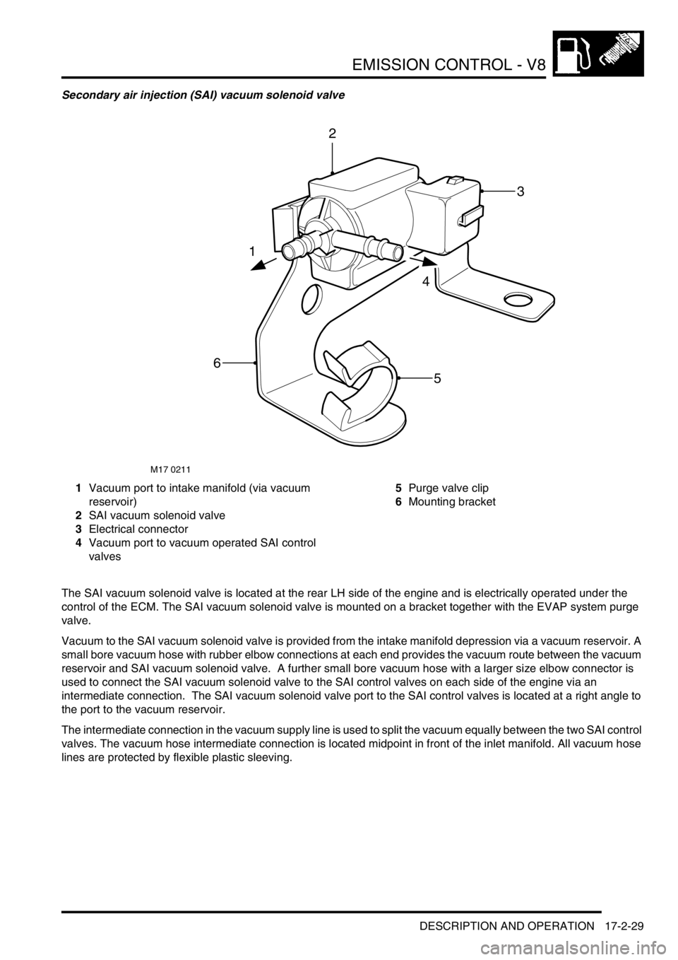
Secondary air injection (SAI) vacuum solenoid valve
1Vacuum port to intake manifold (via vacuum
reservoir)
2SAI vacuum solenoid valve
3Electrical connector
4Vacuum port to vacuum operated SAI control
valves5Purge valve clip
6Mounting bracket
The SAI vacuum solenoid valve is located at the rear LH side of the engine and is electrically operated under the
control of the ECM. The SAI vacuum solenoid valve is mounted on a bracket together with the EVAP system purge
valve.
Vacuum to the SAI vacuum solenoid valve is provided from the intake manifold depression via a vacuum reservoir. A
small bore vacuum hose with rubber elbow connections at each end provides the vacuum route between the vacuum
reservoir and SAI vacuum solenoid valve. A further small bore vacuum hose with a larger size elbow connector is
used to connect the SAI vacuum solenoid valve to the SAI control valves on each side of the engine via an
intermediate connection. The SAI vacuum solenoid valve port to the SAI control valves is located at a right angle to
the port to the vacuum reservoir.
The intermediate connection in the vacuum supply line is used to split the vacuum equally between the two SAI control
valves. The vacuum hose intermediate connection is located midpoint in front of the inlet manifold. All vacuum hose
lines are protected by flexible plastic sleeving.
M17 0211
1
4
2
3
5
6
Page 367 of 1672
EMISSION CONTROL - V8
17-2-30 DESCRIPTION AND OPERATION
Electrical connection to the SAI vacuum solenoid valve is via a 2–pin connector. A 12V electrical power supply to the
SAI vacuum solenoid valve is provided via the Main relay and Fuse 2 in the engine compartment fusebox. The ground
connection is via the ECM which controls the SAI vacuum solenoid valve operation. Note that the harness
connector to the SAI solenoid valve is grey, and must not be confused with the harness connector to the
EVAP system purge valve which is black.
The ECM switches on the SAI vacuum solenoid valve at the same time as initiating SAI pump operation. When the
SAI vacuum solenoid valve is open, a steady vacuum supply is allowed through to open the two vacuum operated
SAI control valves. When the ECM breaks the earth path to the SAI vacuum solenoid valve, the valve closes and
immediately shuts off the vacuum supply to the two SAI control valves at the same time as the SAI pump operation
is terminated.
If the SAI vacuum solenoid valve malfunctions, the following fault codes may be stored in the ECM diagnostic
memory, which can be retrieved using 'Testbook':
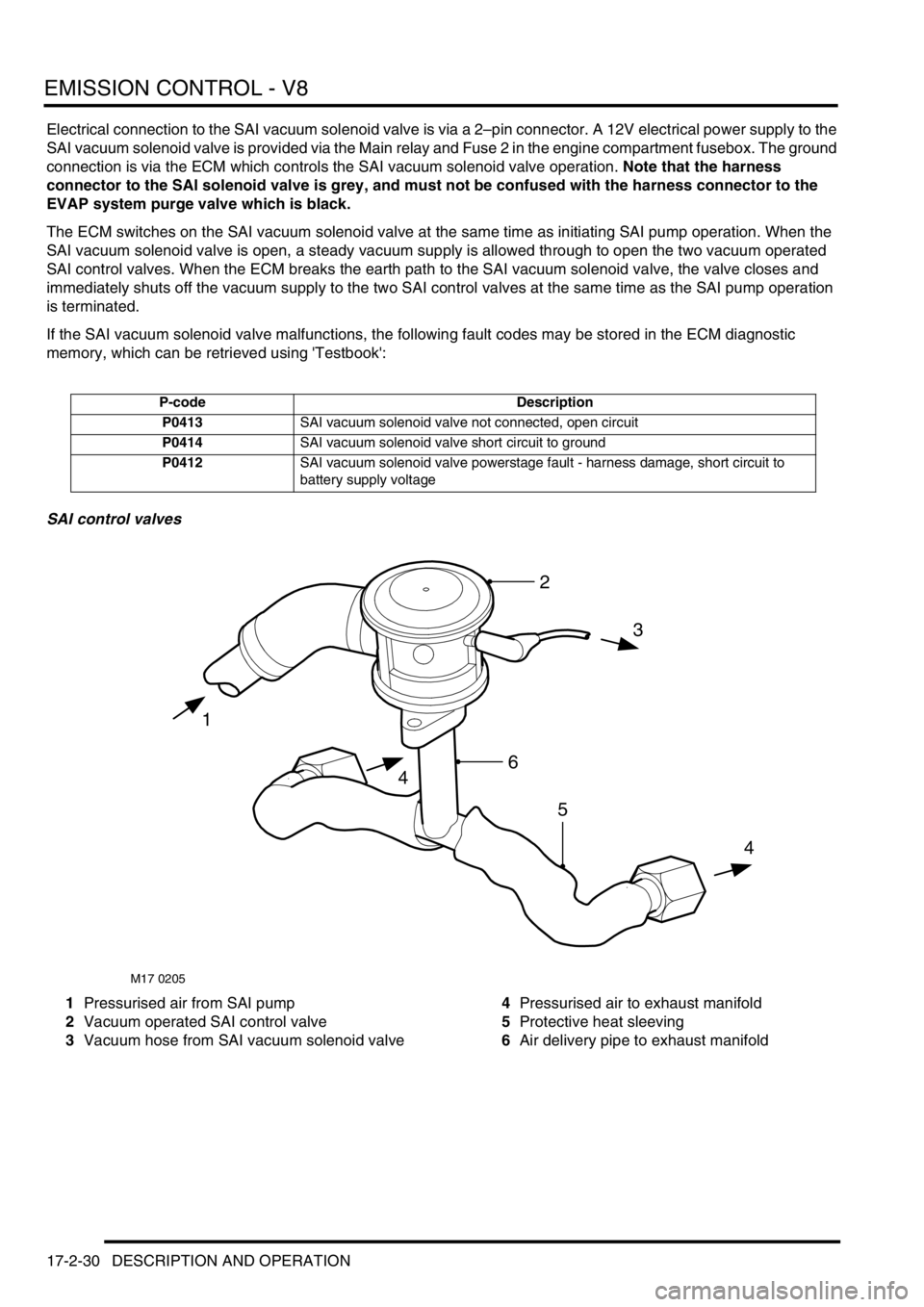
SAI control valves
1Pressurised air from SAI pump
2Vacuum operated SAI control valve
3Vacuum hose from SAI vacuum solenoid valve4Pressurised air to exhaust manifold
5Protective heat sleeving
6Air delivery pipe to exhaust manifold
P-code Description
P0413SAI vacuum solenoid valve not connected, open circuit
P0414SAI vacuum solenoid valve short circuit to ground
P0412SAI vacuum solenoid valve powerstage fault - harness damage, short circuit to
battery supply voltage
M17 0205
1
3
4
4
2
6
5
Page 368 of 1672

EMISSION CONTROL - V8
DESCRIPTION AND OPERATION 17-2-31
The SAI control valves are located on brackets at each side of the engine.
The air injection supply pipes connect to a large bore port on the side of each SAI control valve via a short rubber
connection hose. A small bore vacuum port is located on each SAI control valve at the opposite side to the air injection
supply port. The vacuum supply to each vacuum operated SAI control valve is through small bore nylon hoses from
the SAI vacuum solenoid valve. An intermediate connector is included in the vacuum supply line to split the vacuum
applied to each vacuum operated valve, so that both valves open and close simultaneously.
When a vacuum is applied to the SAI control valves, the valve opens to allow the pressurised air from the SAI pump
through to the exhaust manifolds. The injection air is output from each SAI control valve through a port in the bottom
of each unit. A metal pipe connects between the output port of each SAI control valve and each exhaust manifold via
an intermediate T-piece. The T-piece splits the pressurised air delivered to ports at the outer side of the two centre
exhaust ports on each cylinder head. The pipes between the T-piece and the exhaust manifold are enclosed in
thermal sleeving to protect the surrounding components from the very high heat of the exhaust gas, particularly at
high engine speeds and loads.
When the SAI vacuum solenoid valve is de-energised, the vacuum supply line opens to atmosphere, this causes the
vacuum operated valves to close automatically and completely to prevent further air injection.
If the vacuum operated SAI control valves malfunction, the following fault codes may be stored in the ECM diagnostic
memory, which can be retrieved using 'Testbook':
The above system faults could be attributable to anything which might prevent air delivery to the exhaust manifolds
(e.g. disconnected or blocked SAI delivery pipe, disconnected or blocked vacuum pipe etc.)
P-code Description
P1412SAI system fault (LH side) - air delivery not reaching catalysts
P1414SAI system fault (LH side) - air delivery not reaching catalysts
P1413SAI system fault (LH side) - air delivery not reaching catalysts
P1415SAI system fault (RH side) - air delivery not reaching catalysts
P1417SAI system fault (RH side) - air delivery not reaching catalysts
P1416SAI system fault (RH side) - air delivery not reaching catalysts
Page 369 of 1672
EMISSION CONTROL - V8
17-2-32 DESCRIPTION AND OPERATION
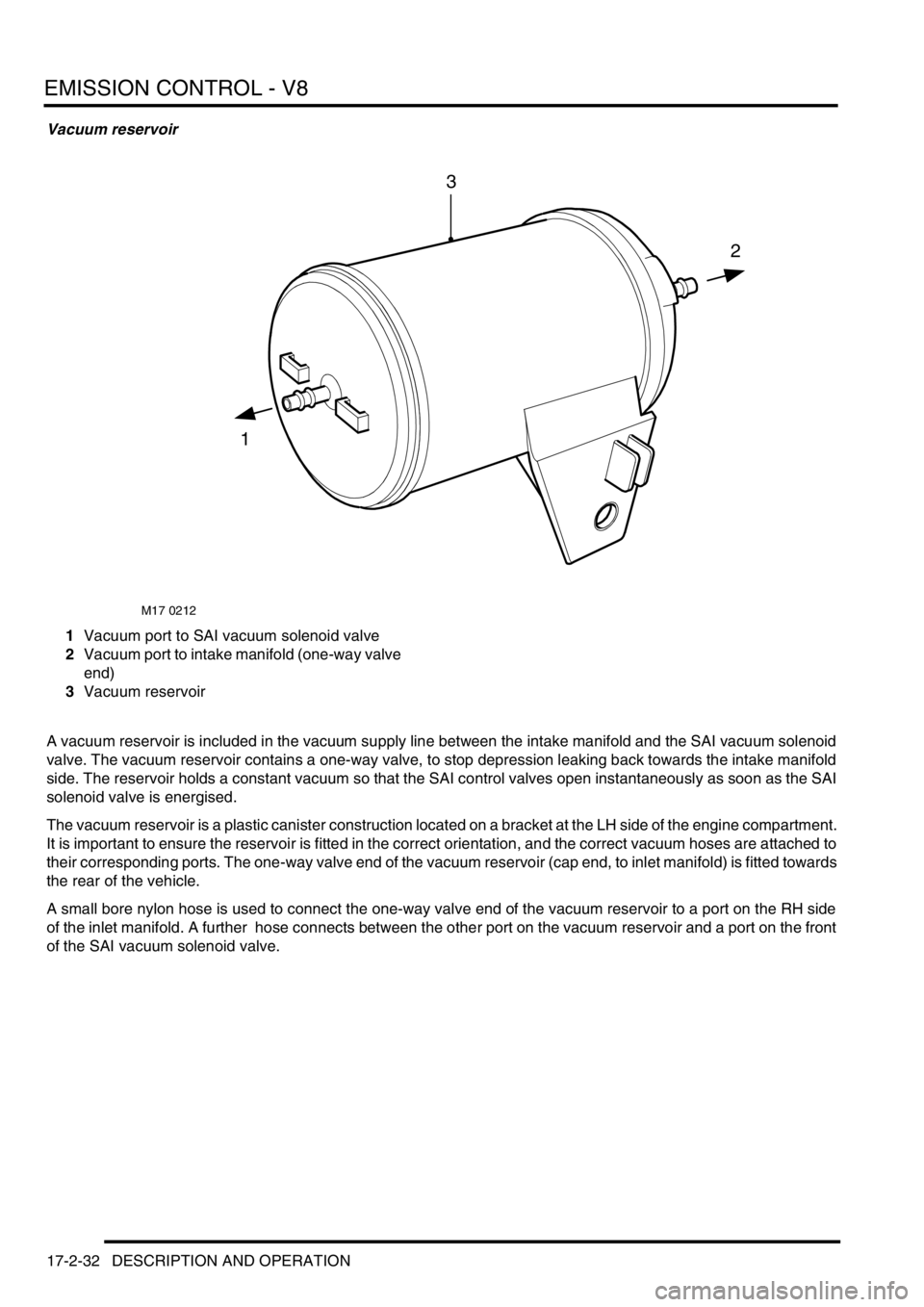
Vacuum reservoir
1Vacuum port to SAI vacuum solenoid valve
2Vacuum port to intake manifold (one-way valve
end)
3Vacuum reservoir
A vacuum reservoir is included in the vacuum supply line between the intake manifold and the SAI vacuum solenoid
valve. The vacuum reservoir contains a one-way valve, to stop depression leaking back towards the intake manifold
side. The reservoir holds a constant vacuum so that the SAI control valves open instantaneously as soon as the SAI
solenoid valve is energised.
The vacuum reservoir is a plastic canister construction located on a bracket at the LH side of the engine compartment.
It is important to ensure the reservoir is fitted in the correct orientation, and the correct vacuum hoses are attached to
their corresponding ports. The one-way valve end of the vacuum reservoir (cap end, to inlet manifold) is fitted towards
the rear of the vehicle.
A small bore nylon hose is used to connect the one-way valve end of the vacuum reservoir to a port on the RH side
of the inlet manifold. A further hose connects between the other port on the vacuum reservoir and a port on the front
of the SAI vacuum solenoid valve.
M17 0212
1
2
3
Page 370 of 1672
EMISSION CONTROL - V8
DESCRIPTION AND OPERATION 17-2-33
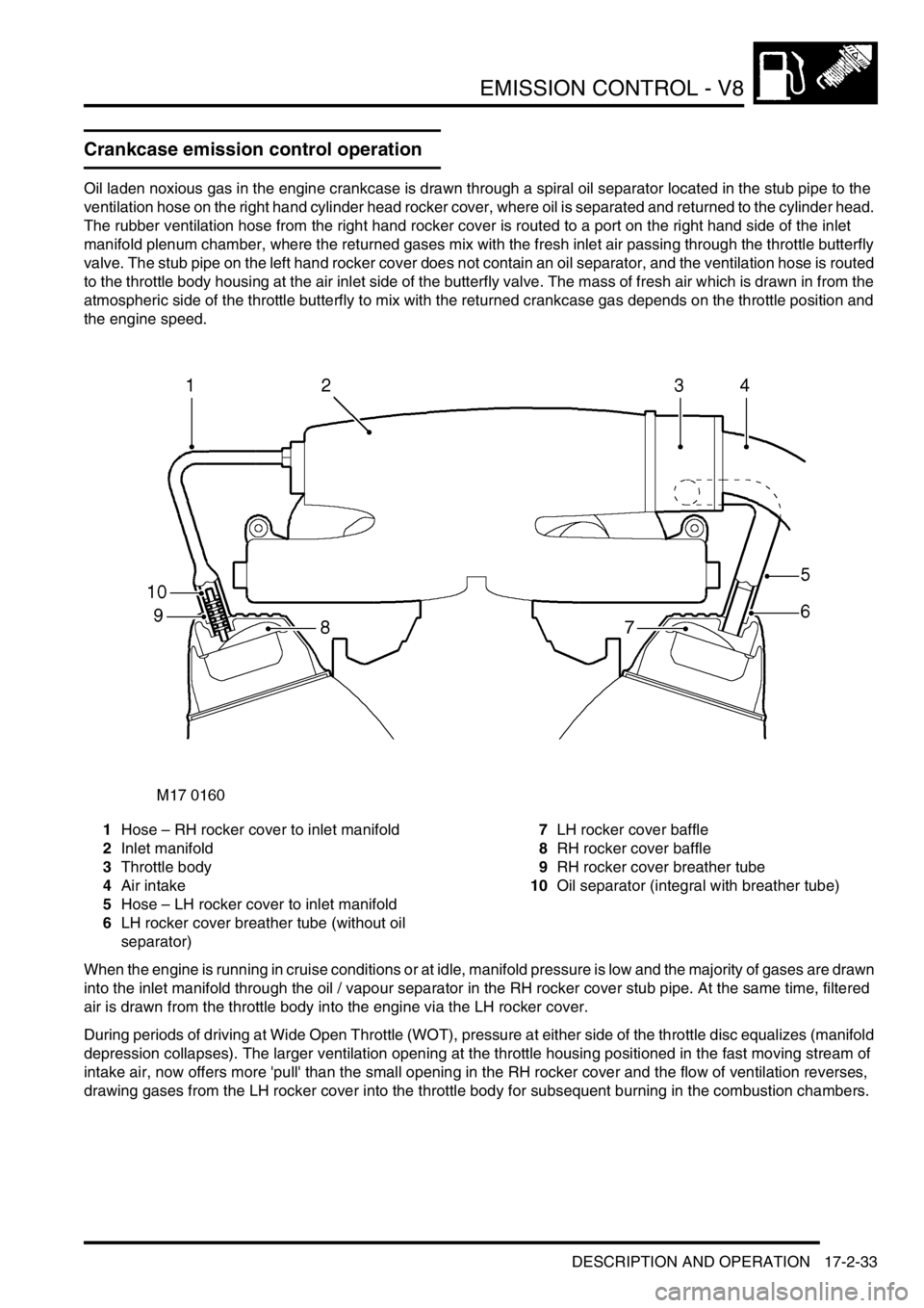
Crankcase emission control operation
Oil laden noxious gas in the engine crankcase is drawn through a spiral oil separator located in the stub pipe to the
ventilation hose on the right hand cylinder head rocker cover, where oil is separated and returned to the cylinder head.
The rubber ventilation hose from the right hand rocker cover is routed to a port on the right hand side of the inlet
manifold plenum chamber, where the returned gases mix with the fresh inlet air passing through the throttle butterfly
valve. The stub pipe on the left hand rocker cover does not contain an oil separator, and the ventilation hose is routed
to the throttle body housing at the air inlet side of the butterfly valve. The mass of fresh air which is drawn in from the
atmospheric side of the throttle butterfly to mix with the returned crankcase gas depends on the throttle position and
the engine speed.
1Hose – RH rocker cover to inlet manifold
2Inlet manifold
3Throttle body
4Air intake
5Hose – LH rocker cover to inlet manifold
6LH rocker cover breather tube (without oil
separator)7LH rocker cover baffle
8RH rocker cover baffle
9RH rocker cover breather tube
10Oil separator (integral with breather tube)
When the engine is running in cruise conditions or at idle, manifold pressure is low and the majority of gases are drawn
into the inlet manifold through the oil / vapour separator in the RH rocker cover stub pipe. At the same time, filtered
air is drawn from the throttle body into the engine via the LH rocker cover.
During periods of driving at Wide Open Throttle (WOT), pressure at either side of the throttle disc equalizes (manifold
depression collapses). The larger ventilation opening at the throttle housing positioned in the fast moving stream of
intake air, now offers more 'pull' than the small opening in the RH rocker cover and the flow of ventilation reverses,
drawing gases from the LH rocker cover into the throttle body for subsequent burning in the combustion chambers.