LAND ROVER DISCOVERY 2002 Workshop Manual
Manufacturer: LAND ROVER, Model Year: 2002, Model line: DISCOVERY, Model: LAND ROVER DISCOVERY 2002Pages: 1672, PDF Size: 46.1 MB
Page 391 of 1672

EMISSION CONTROL - V8
17-2-54 REPAIRS
Pump - Fuel Leak Detection - up to 03MY
$% 17.45.41
Remove
1.Raise the vehicle on lift.
2.Disconnect multiplug from fuel leak detection
pump.
3.Release leak detection air filter hose from top of
pump.
4.Remove 3 Torx screws securing pump to
mounting bracket.
5.Remove clip securing EVAP canister hose to
pump.
6.Release EVAP canister hose from pump.
7.Remove pump.
Refit
1.Connect EVAP canister hose to pump and
secure with clip.
2.Position pump to mounting bracket and secure
with Torx screws.
3.Connect leak detection air filter hose to top of
leak detection pump.
4.Connect multiplug to pump.
5.Lower vehicle.
Pump - fuel leak detection - from 03MY
$% 17.45.41
Remove
1.Raise the vehicle on lift.
2.Disconnect multiplug from the fuel leak
detection pump.
3.Remove 3 screws securing the fuel leak
detection pump to the chassis mounting
bracket.
4.Position absorbent cloth around fuel hoses to
collect any fuel spillage.
5.Disconnect the fuel leak detection filter pipe
from the fuel leak detection pump.
CAUTION: Always fit plugs to open
connections to prevent contamination.
6.Remove and discard clip securing EVAP pipe
to the fuel leak detection pump and disconnect
the pipe.
7.Remove the fuel leak detection pump.
Refit
1.Connect the EVAP pipe to the fuel leak
detection pump and secure with a new clip.
2.Connect the fuel leak detection filter pipe to the
fuel leak detection pump.
3.Remove absorbent cloth.
4.Fit and tighten 3 screws securing the fuel leak
detection pump to the chassis mounting
bracket.
5.Connect multiplug to the fuel leak detection
pump.
6.Lower the vehicle lift.
M17 0235
2
3
4
57
Page 392 of 1672

EMISSION CONTROL - V8
REPAIRS 17-2-55
Filter - fuel leak detection pump - up to
03MY
$% 17.45.42
Remove
1.Remove bolt securing air filter to mounting
bracket and collect nut.
2.Remove clip securing hose to air filter.
3.Release hose from air filter.
4.Remove air filter.
Refit
1.Connect hose to air filter and secure with clip.
2.Position air filter to mounting bracket and
secure with nut and bolt.
Filter - fuel leak detection pump - from
03MY
$% 17.45.42
Remove
1.Remove Allen bolt securing fuel leak detection
pump filter to the mounting bracket.
2.Remove and discard clip securing fuel pipe to
the fuel leak detection pump filter and
disconnect the pipe.
CAUTION: Always fit plugs to open
connections to prevent contamination.
3.Remove the fuel leak detection pump filter.
Refit
1.Connect fuel pipe to the fuel leak detection
pump and secure with a new clip.
2.Position fuel leak detection pump filter to
mounting bracket, fit Allen bolt and tighten to 3
Nm (2.2 lbf.ft).
17M 0224
Page 393 of 1672

EMISSION CONTROL - V8
17-2-56 REPAIRS
Page 394 of 1672

ENGINE MANAGEMENT SYSTEM - TD5
DESCRIPTION AND OPERATION 18-1-1
Deze pagina werd opzettelijk niet gebruikt
Cette page est intentionnellement vierge
Questa pagina è stata lasciata in bianco di proposito Diese Seite ist leer
Esta página foi deixada intencionalmente em branco
Esta página fue dejada en blanco intencionalmente This page is intentionally left blank
ENGIN E MANAGEMENT SY STEM - Td5 DESCRIPTION AND OPERAT ION
Page 395 of 1672

ENGINE MANAGEMENT SYSTEM - TD5
18-1-2 DESCRIPTION AND OPERATION
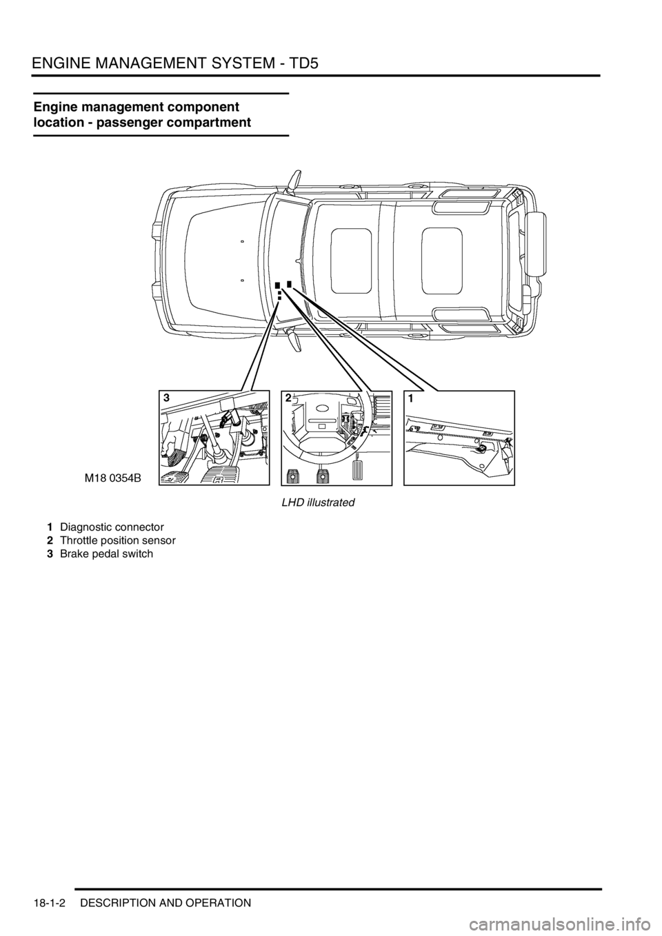
Engine management component
location - passenger compartment
LHD illustrated
1Diagnostic connector
2Throttle position sensor
3Brake pedal switch
Page 396 of 1672

ENGINE MANAGEMENT SYSTEM - TD5
DESCRIPTION AND OPERATION 18-1-3
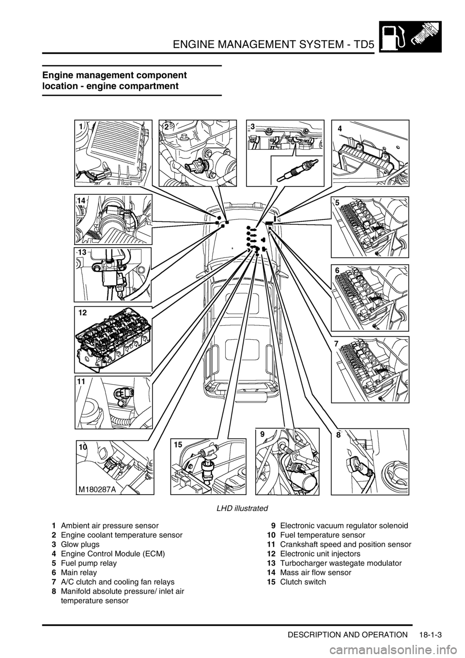
Engine management component
location - engine compartment
LHD illustrated
1Ambient air pressure sensor
2Engine coolant temperature sensor
3Glow plugs
4Engine Control Module (ECM)
5Fuel pump relay
6Main relay
7A/C clutch and cooling fan relays
8Manifold absolute pressure/ inlet air
temperature sensor9Electronic vacuum regulator solenoid
10Fuel temperature sensor
11Crankshaft speed and position sensor
12Electronic unit injectors
13Turbocharger wastegate modulator
14Mass air flow sensor
15Clutch switch
Page 397 of 1672

ENGINE MANAGEMENT SYSTEM - TD5
18-1-4 DESCRIPTION AND OPERATION
Engine management block diagram
Page 398 of 1672

ENGINE MANAGEMENT SYSTEM - TD5
DESCRIPTION AND OPERATION 18-1-5
1Mass air flow sensor
2Ambient air pressure sensor
3Manifold absolute pressure/ inlet air
temperature sensor
4Engine coolant temperature sensor
5Crankshaft speed and position sensor
6Throttle position sensor
7Fuel temperature sensor
8Brake pedal switch
9Clutch switch
10High/ Low ratio switch
11Main relay
12Malfunction indicator lamp
13Fuel pump relay
14Glow plug warning lamp
15Glow plugs16Electronic unit injectors
17Turbocharger wastegate modulator
18EGR modulator
19Diagnostic connector
20Engine control module
21Cruise control master switch
22Cruise control SET+ switch
23Cruise control RES switch
24Air conditioning clutch relay
25Air conditioning cooling fan relay
26Electronic automatic transmission ECU
27Self levelling and anti-lock brakes ECU
28Instrument cluster
29Body control unit
Page 399 of 1672

ENGINE MANAGEMENT SYSTEM - TD5
18-1-6 DESCRIPTION AND OPERATION
Description
General
An engine control module (ECM) controls the five-cylinder direct injection diesel engine, and works on the drive by
wire principle. This means there is no throttle cable, the ECM controls the drivers needs via a signal from the Throttle
Position (TP) sensor on the throttle pedal.
The ECM is a full authoritative diesel specific microprocessor that also incorporates features for cruise control and air
conditioning control. In addition, the ECM supplies output control for the exhaust gas recirculation and turbocharger
boost pressure. The ECM has a self-diagnostic function, which is able to provide backup strategies for most sensor
failures.
The ECM processes information from the following input sources:
lMass air flow sensor.
lAmbient air pressure sensor.
lManifold absolute pressure/inlet air temperature sensor.
lEngine coolant temperature sensor.
lCrankshaft speed and position sensor.
lThrottle position sensor.
lFuel temperature sensor.
lAir conditioning request.
lAir conditioning fan request.
lBrake pedal switch.
lClutch switch.
lCruise control master switch.
lCruise control SET+ switch.
lCruise control RES switch.
lHigh/low ratio switch.
The input from the sensors constantly updates the ECM with the current operating condition of the engine. Once the
ECM has compared current information with stored information within its memory, it can make any adjustment it
requires to the operation of the engine via the following:
lAir conditioning clutch relay.
lAir conditioning cooling fan relay.
lElectronic vacuum regulator solenoid.
lMalfunction indicator lamp.
lFuel pump relay.
lGlow plug warning lamp.
lGlow plugs.
lFuel injectors.
lMain relay.
lTurbocharger wastegate modulator.
lTemperature gauge.
The ECM interfaces with the following:
lElectronic Automatic Transmission (EAT).
lSelf Levelling and Anti-lock Brakes System (SLABS).
lSerial communication link.
lInstrument cluster.
lBody Control Unit (BCU).
Page 400 of 1672

ENGINE MANAGEMENT SYSTEM - TD5
DESCRIPTION AND OPERATION 18-1-7
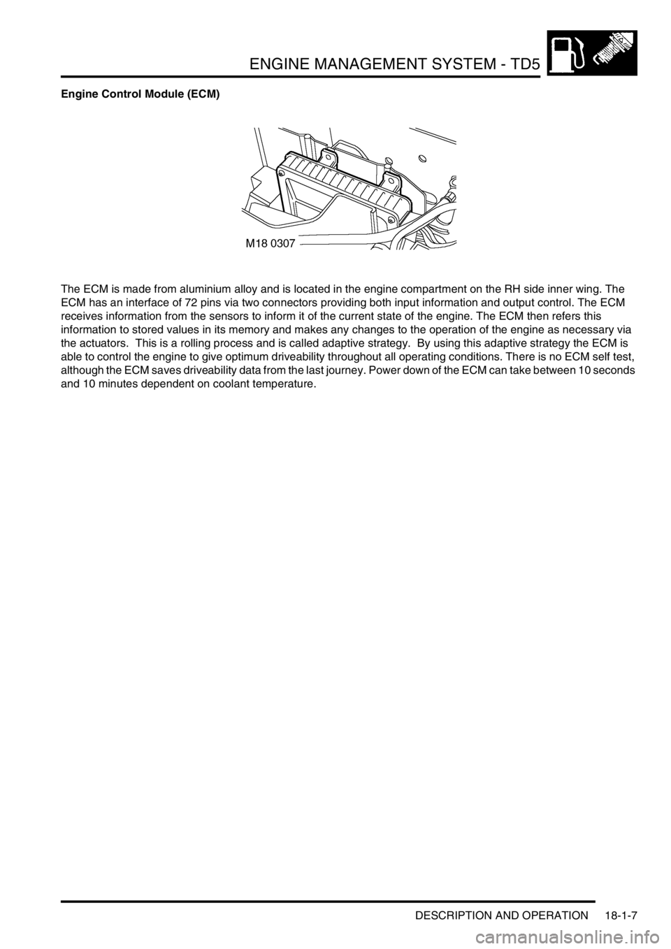
Engine Control Module (ECM)
The ECM is made from aluminium alloy and is located in the engine compartment on the RH side inner wing. The
ECM has an interface of 72 pins via two connectors providing both input information and output control. The ECM
receives information from the sensors to inform it of the current state of the engine. The ECM then refers this
information to stored values in its memory and makes any changes to the operation of the engine as necessary via
the actuators. This is a rolling process and is called adaptive strategy. By using this adaptive strategy the ECM is
able to control the engine to give optimum driveability throughout all operating conditions. There is no ECM self test,
although the ECM saves driveability data from the last journey. Power down of the ECM can take between 10 seconds
and 10 minutes dependent on coolant temperature.