LAND ROVER DISCOVERY 2002 Workshop Manual
Manufacturer: LAND ROVER, Model Year: 2002, Model line: DISCOVERY, Model: LAND ROVER DISCOVERY 2002Pages: 1672, PDF Size: 46.1 MB
Page 381 of 1672
EMISSION CONTROL - V8
17-2-44 REPAIRS
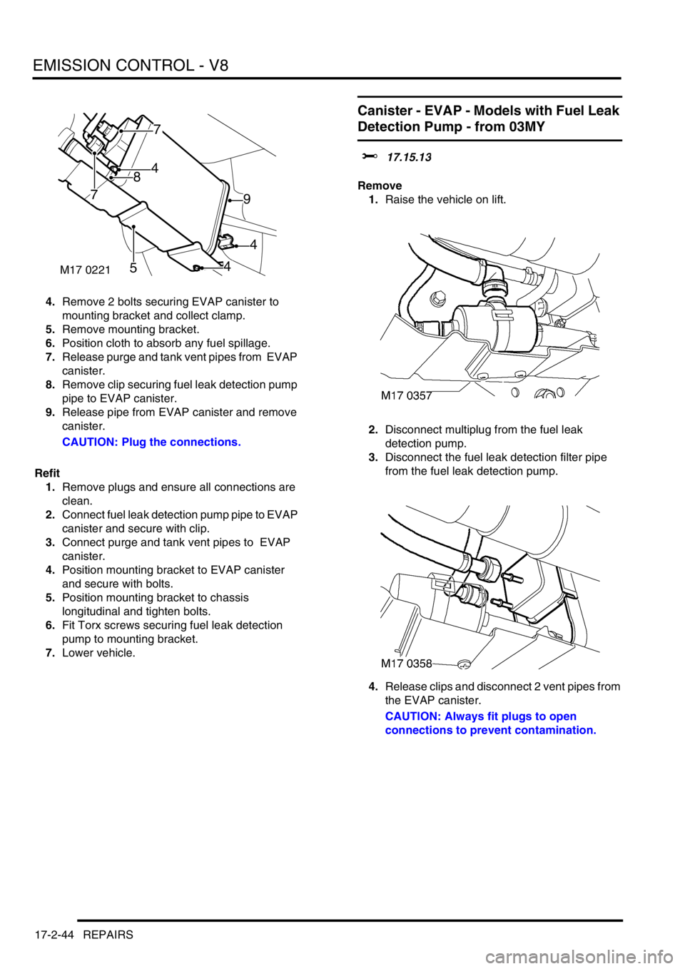
4.Remove 2 bolts securing EVAP canister to
mounting bracket and collect clamp.
5.Remove mounting bracket.
6.Position cloth to absorb any fuel spillage.
7.Release purge and tank vent pipes from EVAP
canister.
8.Remove clip securing fuel leak detection pump
pipe to EVAP canister.
9.Release pipe from EVAP canister and remove
canister.
CAUTION: Plug the connections.
Refit
1.Remove plugs and ensure all connections are
clean.
2.Connect fuel leak detection pump pipe to EVAP
canister and secure with clip.
3.Connect purge and tank vent pipes to EVAP
canister.
4.Position mounting bracket to EVAP canister
and secure with bolts.
5.Position mounting bracket to chassis
longitudinal and tighten bolts.
6.Fit Torx screws securing fuel leak detection
pump to mounting bracket.
7.Lower vehicle.
Canister - EVAP - Models with Fuel Leak
Detection Pump - from 03MY
$% 17.15.13
Remove
1.Raise the vehicle on lift.
2.Disconnect multiplug from the fuel leak
detection pump.
3.Disconnect the fuel leak detection filter pipe
from the fuel leak detection pump.
4.Release clips and disconnect 2 vent pipes from
the EVAP canister.
CAUTION: Always fit plugs to open
connections to prevent contamination.
M17 0221
4
4
4
9
7
7
5
8
Page 382 of 1672
EMISSION CONTROL - V8
REPAIRS 17-2-45
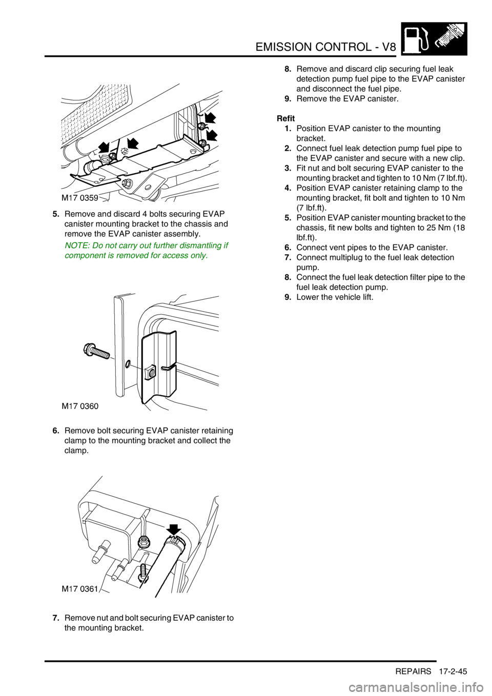
5.Remove and discard 4 bolts securing EVAP
canister mounting bracket to the chassis and
remove the EVAP canister assembly.
NOTE: Do not carry out further dismantling if
component is removed for access only.
6.Remove bolt securing EVAP canister retaining
clamp to the mounting bracket and collect the
clamp.
7.Remove nut and bolt securing EVAP canister to
the mounting bracket.8.Remove and discard clip securing fuel leak
detection pump fuel pipe to the EVAP canister
and disconnect the fuel pipe.
9.Remove the EVAP canister.
Refit
1.Position EVAP canister to the mounting
bracket.
2.Connect fuel leak detection pump fuel pipe to
the EVAP canister and secure with a new clip.
3.Fit nut and bolt securing EVAP canister to the
mounting bracket and tighten to 10 Nm (7 lbf.ft).
4.Position EVAP canister retaining clamp to the
mounting bracket, fit bolt and tighten to 10 Nm
(7 lbf.ft).
5.Position EVAP canister mounting bracket to the
chassis, fit new bolts and tighten to 25 Nm (18
lbf.ft).
6.Connect vent pipes to the EVAP canister.
7.Connect multiplug to the fuel leak detection
pump.
8.Connect the fuel leak detection filter pipe to the
fuel leak detection pump.
9.Lower the vehicle lift.
Page 383 of 1672
EMISSION CONTROL - V8
17-2-46 REPAIRS
Valve - purge control
$% 17.15.39
Remove
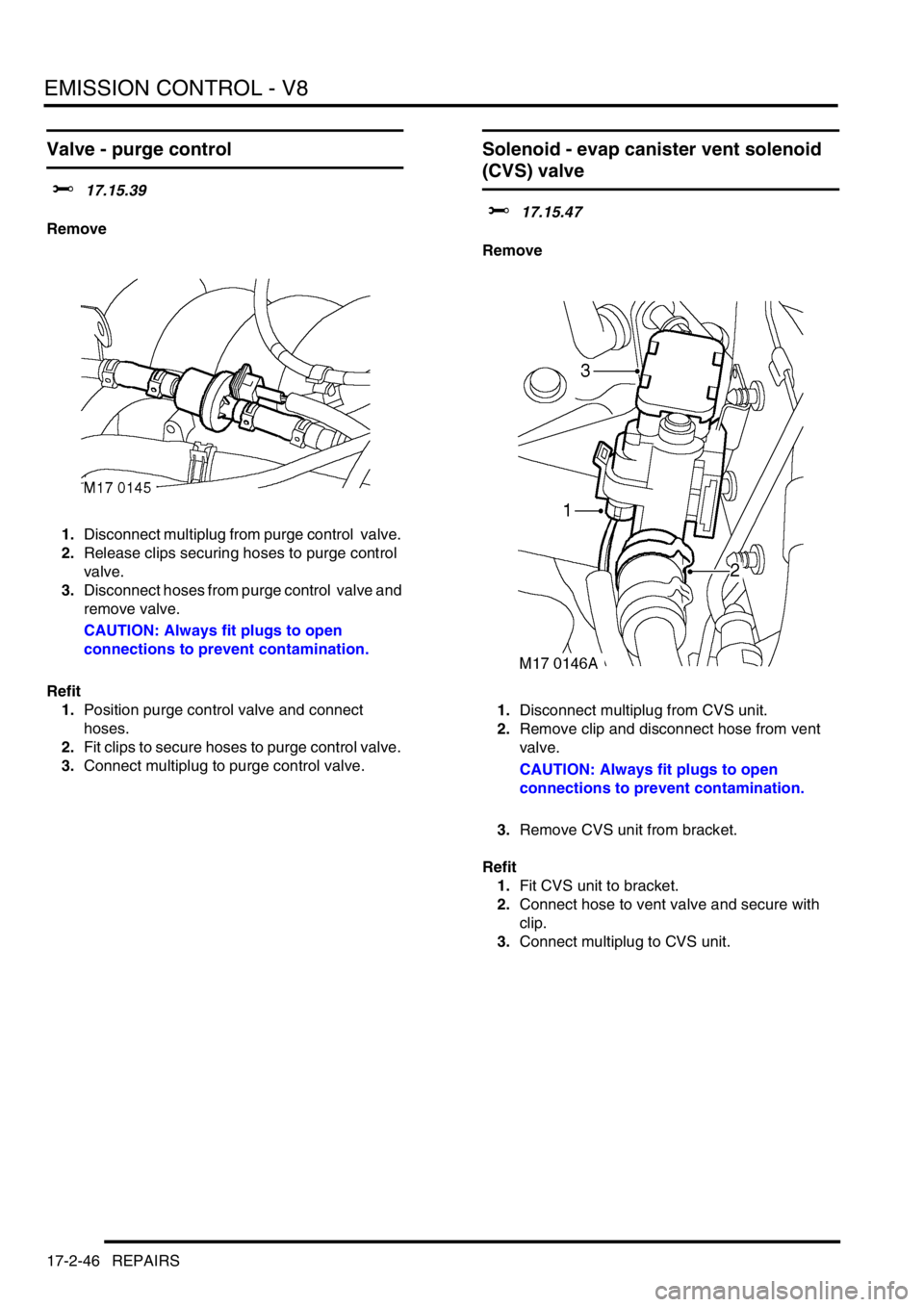
1.Disconnect multiplug from purge control valve.
2.Release clips securing hoses to purge control
valve.
3.Disconnect hoses from purge control valve and
remove valve.
CAUTION: Always fit plugs to open
connections to prevent contamination.
Refit
1.Position purge control valve and connect
hoses.
2.Fit clips to secure hoses to purge control valve.
3.Connect multiplug to purge control valve.
Solenoid - evap canister vent solenoid
(CVS) valve
$% 17.15.47
Remove
1.Disconnect multiplug from CVS unit.
2.Remove clip and disconnect hose from vent
valve.
CAUTION: Always fit plugs to open
connections to prevent contamination.
3.Remove CVS unit from bracket.
Refit
1.Fit CVS unit to bracket.
2.Connect hose to vent valve and secure with
clip.
3.Connect multiplug to CVS unit.
Page 384 of 1672
EMISSION CONTROL - V8
REPAIRS 17-2-47
Sensor - heated oxygen (HO2S) - pre-
catalytic converter
$% 19.22.16
Remove
1.Raise vehicle on a ramp.
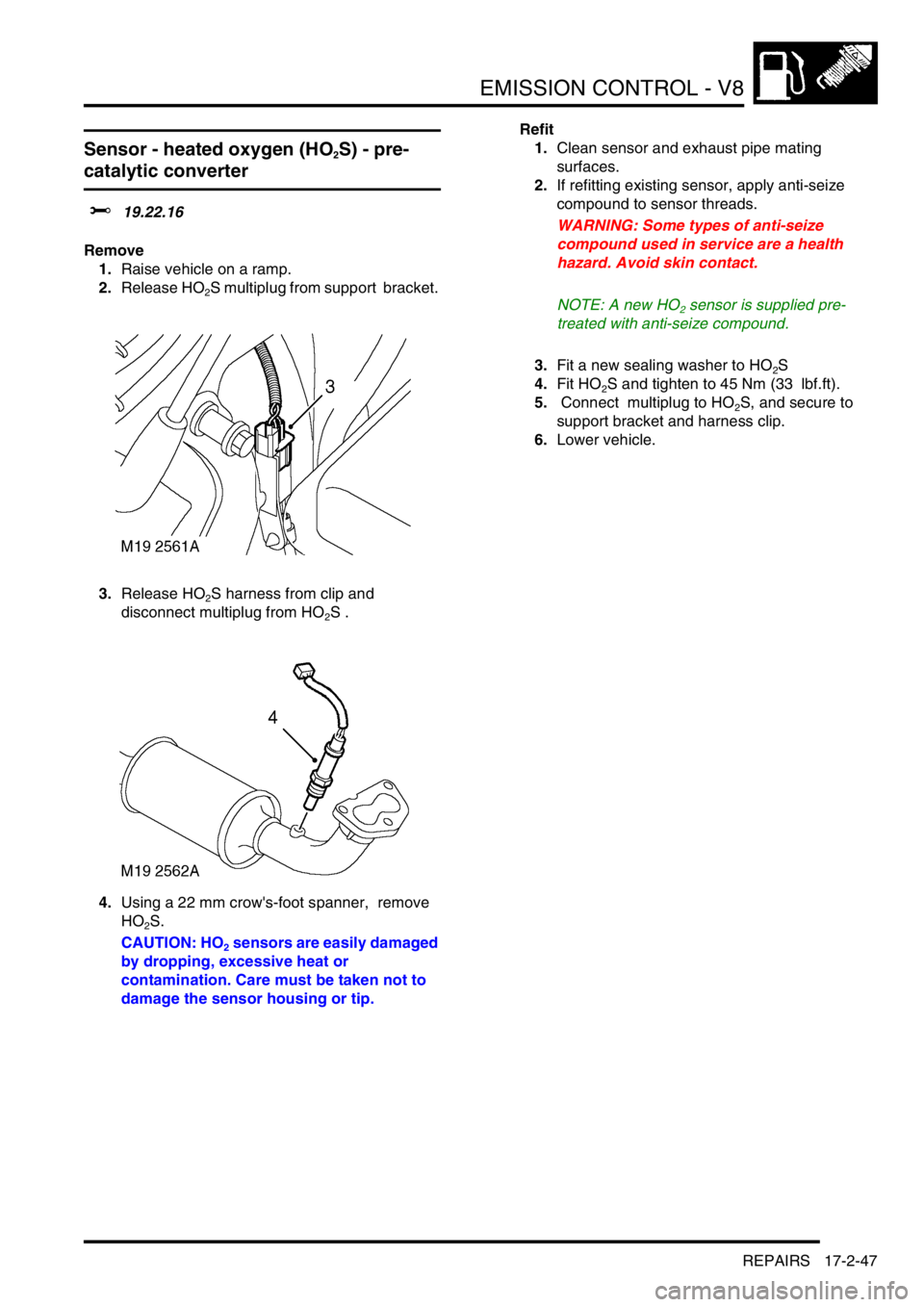
2.Release HO
2S multiplug from support bracket.
3.Release HO
2S harness from clip and
disconnect multiplug from HO
2S .
4.Using a 22 mm crow's-foot spanner, remove
HO
2S.
CAUTION: HO
2 sensors are easily damaged
by dropping, excessive heat or
contamination. Care must be taken not to
damage the sensor housing or tip.Refit
1.Clean sensor and exhaust pipe mating
surfaces.
2.If refitting existing sensor, apply anti-seize
compound to sensor threads.
WARNING: Some types of anti-seize
compound used in service are a health
hazard. Avoid skin contact.
NOTE: A new HO
2 sensor is supplied pre-
treated with anti-seize compound.
3.Fit a new sealing washer to HO
2S
4.Fit HO
2S and tighten to 45 Nm (33 lbf.ft).
5. Connect multiplug to HO
2S, and secure to
support bracket and harness clip.
6.Lower vehicle.
Page 385 of 1672

EMISSION CONTROL - V8
17-2-48 REPAIRS
Sensor - heated oxygen (HO2S) - post-
catalytic converter
$% 19.22.17
Remove
1.Raise vehicle on ramp.
2.Release HO
2S multiplug from support bracket.
3.Disconnect HO
2S multiplug from harness.
4.Using a 22 mm crowsfoot spanner, remove
HO
2S.
CAUTION: HO2 sensors are easily damaged
by dropping, excessive heat or
contamination. Care must be taken not to
damage the sensor housing or tip.Refit
1.Clean sensor and exhaust pipe mating
surfaces.
2.If refitting existing sensor, apply anti-seize
compound to sensor threads.
WARNING: Some types of anti-seize
compound used in service are a health
hazard. Avoid skin contact.
NOTE: A new HO2 sensor is supplied pre-
treated with anti-seize compound.
3.Fit a new sealing washer to HO
2S
4.Fit HO
2S and tighten to 45 Nm (33 lbf.ft).
5. Connect HO
2S multiplug to harness and fit
harness to bracket.
6.Secure harness to clip.
7.Lower vehicle.
Page 386 of 1672

EMISSION CONTROL - V8
REPAIRS 17-2-49
Control Valve - Secondary Air Injection
(SAI)
$% 17.25.02
Remove
1.Release clip and disconnect air hose from
valve.
2.Disconnect vacuum hose from valve.
3.Remove 2 bolts securing valve to air manifold.
4.Remove valve and discard gasket.
Refit
1.Clean SAI control valve and mating face on
manifold.
2.Fit new gasket and fit valve. Tighten bolts to 10
Nm (7 lbf.ft).
3.Connect vacuum hose.
4.Connect air hose and secure with clip.
Reservoir - Vacuum - Secondary Air
Injection (SAI) - up to 03MY
$% 17.25.04
Remove
1.Disconnect 2 vacuum hoses from reservoir.
2.Remove bolt securing reservoir to mounting
bracket and collect reservoir.
Refit
1.Position reservoir to mounting bracket and
tighten bolt to 10 Nm.
2.Connect vacuum hoses to reservoir.
M17 0222
1
2
3
4
M17 0227
2
1
1
Page 387 of 1672

EMISSION CONTROL - V8
17-2-50 REPAIRS
Reservoir - vacuum - Secondary Air
Injection (SAI) - from 03MY
$% 17.25.04
Remove
1.Disconnect 2 vacuum pipes from air reservoir.
2.Remove bolt securing air reservoir to air pump
and remove the reservoir.
Refit
1.Position air reservoir to air pump, fit bolt and
tighten to 10 Nm (7 lbf.ft).
2.Connect vacuum pipes to the air reservoir.
Pump - Air - Secondary Air Injection
(SAI)
$% 17.25.07
Remove
1.Disconnect multiplug from air pump.
2.Release clip and disconnect air hose from air
pump.
3.Remove bolt securing air pump bracket to
body.
4.Remove air pump and bracket assembly.
5.Remove 3 nuts securing bracket to air pump
and collect bracket.
6.Remove 3 mountings from air pump.
Refit
1.Fit mountings to air pump and tighten to 10
Nm.
2.Fit bracket to air pump mountings and tighten
nuts to 10 Nm.
3.Position air pump assembly and tighten bolt to
20 Nm.
4.Connect air hose to SAI pump.
5.Connect multiplug to air pump.
M17 0225
2
1
3
4
M17 0226
5
5
6
Page 388 of 1672

EMISSION CONTROL - V8
REPAIRS 17-2-51
Air Manifold - LH - Secondary Air
Injection (SAI)
$% 17.25.17
Remove
1.Remove SAI control valve.
+ EMISSION CONTROL - V8,
REPAIRS, Control Valve - Secondary Air
Injection (SAI).
2.Loosen 2 union nuts securing air manifold to
cylinder head adaptors.
3.Remove 2 nuts securing air manifold bracket to
inlet manifold.
4.Remove air manifold.
Refit
1.Clean air manifold and cylinder head adaptors.
2.Fit air manifold and start union nuts.
3.Fit nuts securing air manifold to inlet manifold.
4.Tighten air manifold unions to 25 Nm.
5.Fit SAI control valve.
+ EMISSION CONTROL - V8,
REPAIRS, Control Valve - Secondary Air
Injection (SAI).
Air Manifold - RH - Secondary Air
Injection (SAI)
$% 17.25.18
Remove
1.Remove SAI control valve.
+ EMISSION CONTROL - V8,
REPAIRS, Control Valve - Secondary Air
Injection (SAI).
2.Remove heater feed pipe.
+ HEATING AND VENTILATION,
REPAIRS, Pipe - Heater - Feed.
3.Loosen 2 union nuts securing air manifold to
cylinder head adaptors.
4.Remove nut securing air manifold bracket to
inlet manifold.
5.Remove air manifold.
Refit
1.Clean air manifold and cylinder head adaptors.
2.Fit air manifold and start union nuts.
3.Fit nut securing air manifold to inlet manifold.
4.Tighten air manifold unions to 25 Nm.
5.Fit heater feed pipe.
+ HEATING AND VENTILATION,
REPAIRS, Pipe - Heater - Feed.
6.Fit SAI control valve.
+ EMISSION CONTROL - V8,
REPAIRS, Control Valve - Secondary Air
Injection (SAI).
M17 0234
4
3
2
2
M17 0223
43
3
5
Page 389 of 1672

EMISSION CONTROL - V8
17-2-52 REPAIRS
Solenoid - Vacuum - Secondary Air
Injection (SAI)
$% 17.25.47
Remove
1.Release multiplug from solenoid.
2.Disconnect 2 vacuum hoses from solenoid.
3.Release solenoid from mounting bracket and
remove.
Refit
1.Secure solenoid to mounting bracket.
2.Connect vacuum hoses and multiplug to
solenoid.
Pipe - Secondary Air Injection (SAI)
$% 17.25.59
Remove
1.Loosen clip securing RH SAI control valve hose
to air injection pipe.
2.Release hose from air injection pipe.
3.Loosen clip securing SAI pump hose to air
injection pipe.
4.Release hose from air injection pipe.
5.Loosen clip securing LH SAI control valve hose
to air injection pipe.
6.Release hose from air injection pipe.
7.Disconnect multiplug from SAI vacuum
solenoid.
M17 0236
1
2
2
3
M17 0230
Page 390 of 1672
EMISSION CONTROL - V8
REPAIRS 17-2-53
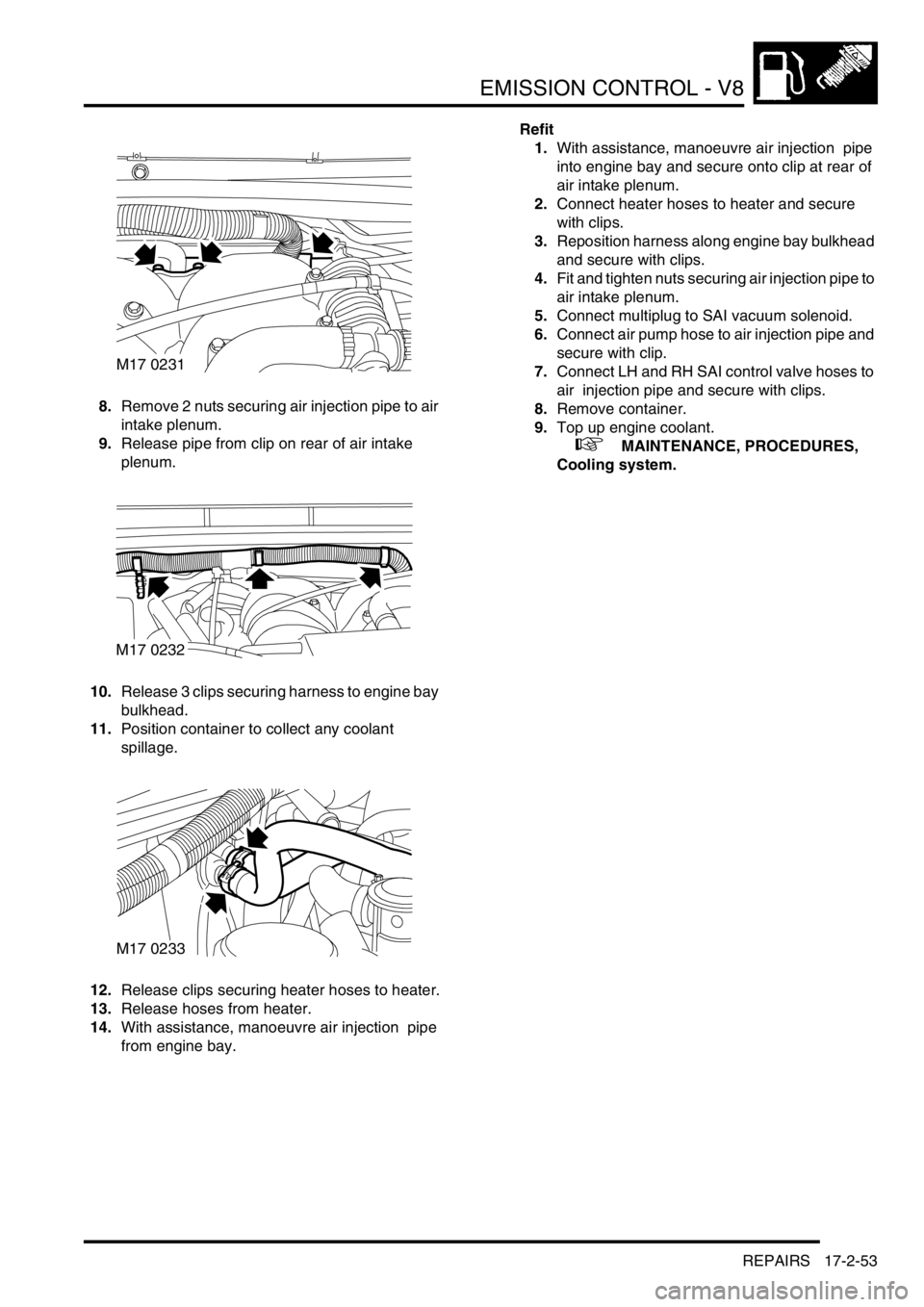
8.Remove 2 nuts securing air injection pipe to air
intake plenum.
9.Release pipe from clip on rear of air intake
plenum.
10.Release 3 clips securing harness to engine bay
bulkhead.
11.Position container to collect any coolant
spillage.
12.Release clips securing heater hoses to heater.
13.Release hoses from heater.
14.With assistance, manoeuvre air injection pipe
from engine bay.Refit
1.With assistance, manoeuvre air injection pipe
into engine bay and secure onto clip at rear of
air intake plenum.
2.Connect heater hoses to heater and secure
with clips.
3.Reposition harness along engine bay bulkhead
and secure with clips.
4.Fit and tighten nuts securing air injection pipe to
air intake plenum.
5.Connect multiplug to SAI vacuum solenoid.
6.Connect air pump hose to air injection pipe and
secure with clip.
7.Connect LH and RH SAI control valve hoses to
air injection pipe and secure with clips.
8.Remove container.
9.Top up engine coolant.
+ MAINTENANCE, PROCEDURES,
Cooling system.
M17 0231
M17 0232
M17 0233