ECU LAND ROVER DISCOVERY 2002 Workshop Manual
[x] Cancel search | Manufacturer: LAND ROVER, Model Year: 2002, Model line: DISCOVERY, Model: LAND ROVER DISCOVERY 2002Pages: 1672, PDF Size: 46.1 MB
Page 845 of 1672

AUTOMATIC GEARBOX - ZF4HP22 - 24
44-48 REPAIRS
5.Remove 6 long bolts securing valve body to
gearbox.
6.Remove 5 short bolts securing valve body to
gearbox.7.Release speed sensor and remove valve body.
8.Remove and discard 'O' ring from multiplug
connector.
Refit
1.Clean valve body and mating faces.
2.Fit new 'O' ring to multiplug connector block.
3.With assistance, position multiplug to gearbox
housing and tighten nut.
4.Align valve body to gearbox, ensure manual
valve is correctly located. Position speed
sensor retaining bracket, and tighten screws
to 8 Nm (6 lbf.ft).
5.Connect multiplug to gearbox connector.
6.Fit gearbox oil filter.
+ AUTOMATIC GEARBOX - ZF4HP22
- 24, REPAIRS, Filter - oil.
Page 846 of 1672

AUTOMATIC GEARBOX - ZF4HP22 - 24
REPAIRS 44-49
Seal - valve body
$% 44.20.13
Remove
1.Remove valve body assembly.
+ AUTOMATIC GEARBOX - ZF4HP22
- 24, REPAIRS, Valve body assembly.
2.Remove circlips and springs from gearbox
casing noting location of long and short
springs.
3.Using tool LRT-44-005, remove and discard
seals from gearbox casing.
Refit
1.Clean gearbox casing, springs and circlips.
2.Fit new seals using tool LRT-44-005, ensure
seals are fully seated.3.Position springs in their correct locations and
secure with circlips.
4.Fit valve body assembly.
+ AUTOMATIC GEARBOX - ZF4HP22
- 24, REPAIRS, Valve body assembly.
Page 847 of 1672

AUTOMATIC GEARBOX - ZF4HP22 - 24
44-50 REPAIRS
Pressure regulator
$% 44.40.22
Remove
1.Remove valve body assembly.
+ AUTOMATIC GEARBOX - ZF4HP22
- 24, REPAIRS, Valve body assembly.
2.Release and remove clip securing pressure
regulator solenoid valve harness to valve body.
3.Disconnect multiplug from pressure regulator
solenoid valve.
4.Remove 5 Torx screws securing pressure
regulator to valve body and remove pressure
regulator.Refit
1.Clean pressure regulator and mating face with
a lint free cloth.
2.Position pressure regulator to valve body, fit
Torx screws and tighten to 8 Nm (6 lbf.ft).
3.Connect multiplug to pressure regulator
solenoid valve, fit clip and secure harness to
valve body.
4.Fit valve body assembly.
+ AUTOMATIC GEARBOX - ZF4HP22
- 24, REPAIRS, Valve body assembly.
M44 1351
3
Page 848 of 1672

AUTOMATIC GEARBOX - ZF4HP22 - 24
REPAIRS 44-51
Lock-up solenoid valve (MV 3)
$% 44.15.35
Remove
1.Remove valve body assembly.
+ AUTOMATIC GEARBOX - ZF4HP22
- 24, REPAIRS, Valve body assembly.
2.Disconnect multiplug from lock-up solenoid
valve and release harness from clip.
3.Remove Torx screw and retaining fork securing
solenoid valve to valve body.
4.Remove solenoid valve from valve body.
Refit
1.Clean lock-up solenoid valve with lint free cloth.
2.Position solenoid valve in valve body.
3.Position retaining fork, fit and tighten Torx
screw to 8 Nm (6 lbf.ft).
4.Connect multiplug to lock-up solenoid valve
and secure harness in clip.
5.Fit valve body assembly.
+ AUTOMATIC GEARBOX - ZF4HP22
- 24, REPAIRS, Valve body assembly.
Solenoids - shift control valves (MV 1 &
2)
$% 44.15.45
Remove
1.Remove valve body assembly.
+ AUTOMATIC GEARBOX - ZF4HP22
- 24, REPAIRS, Valve body assembly.
2.Remove 3 Torx screws securing lock-up
solenoid valve assembly to valve body and
move solenoid aside.
NOTE: This is to gain access to remove Torx
screw and MV2 shift control valve.
3.Note their fitted position and disconnect
multiplugs from shift control valves MV 1 and
MV 2.
4.Remove Torx screw and retaining fork securing
MV2 shift control solenoid valve to valve body.
Note that the tag on the retaining fork faces
towards the valve body.
5.Remove shift control valve from valve body.
M44 1354A
2
3
4
M44 13521
M44 1353A
Page 849 of 1672

AUTOMATIC GEARBOX - ZF4HP22 - 24
44-52 REPAIRS
Refit
1.Clean MV2 shift control solenoid valve with lint
free cloth.
2.Position MV2 shift control solenoid valve to
valve body.
3.Position retaining fork, fit Torx screw and
tighten to 8 Nm (6 lbf.ft).
4.Connect multiplugs to both shift control
solenoid valves.
5.Clean lock-up solenoid valve assembly with a
lint-free cloth.
6.Position lock-up valve assembly, fit and tighten
Torx screws to 8 Nm (6 lbf.ft).
7.Fit valve body assembly.
+ AUTOMATIC GEARBOX - ZF4HP22
- 24, REPAIRS, Valve body assembly.
Harness - solenoid valves
$% 44.15.52
Remove
1.Remove valve body assembly.
+ AUTOMATIC GEARBOX - ZF4HP22
- 24, REPAIRS, Valve body assembly.
2.Release and remove clip securing pressure
regulator solenoid harness to valve body.
3.Disconnect multiplug from pressure regulator
solenoid valve.
4.Disconnect multiplugs from lock-up solenoid
valve, shift control solenoid valves MV 1 and
MV 2.
5.Release harness from 5 clips on valve body
and remove harness.
M44 1350
M44 1355
Page 850 of 1672

AUTOMATIC GEARBOX - ZF4HP22 - 24
REPAIRS 44-53
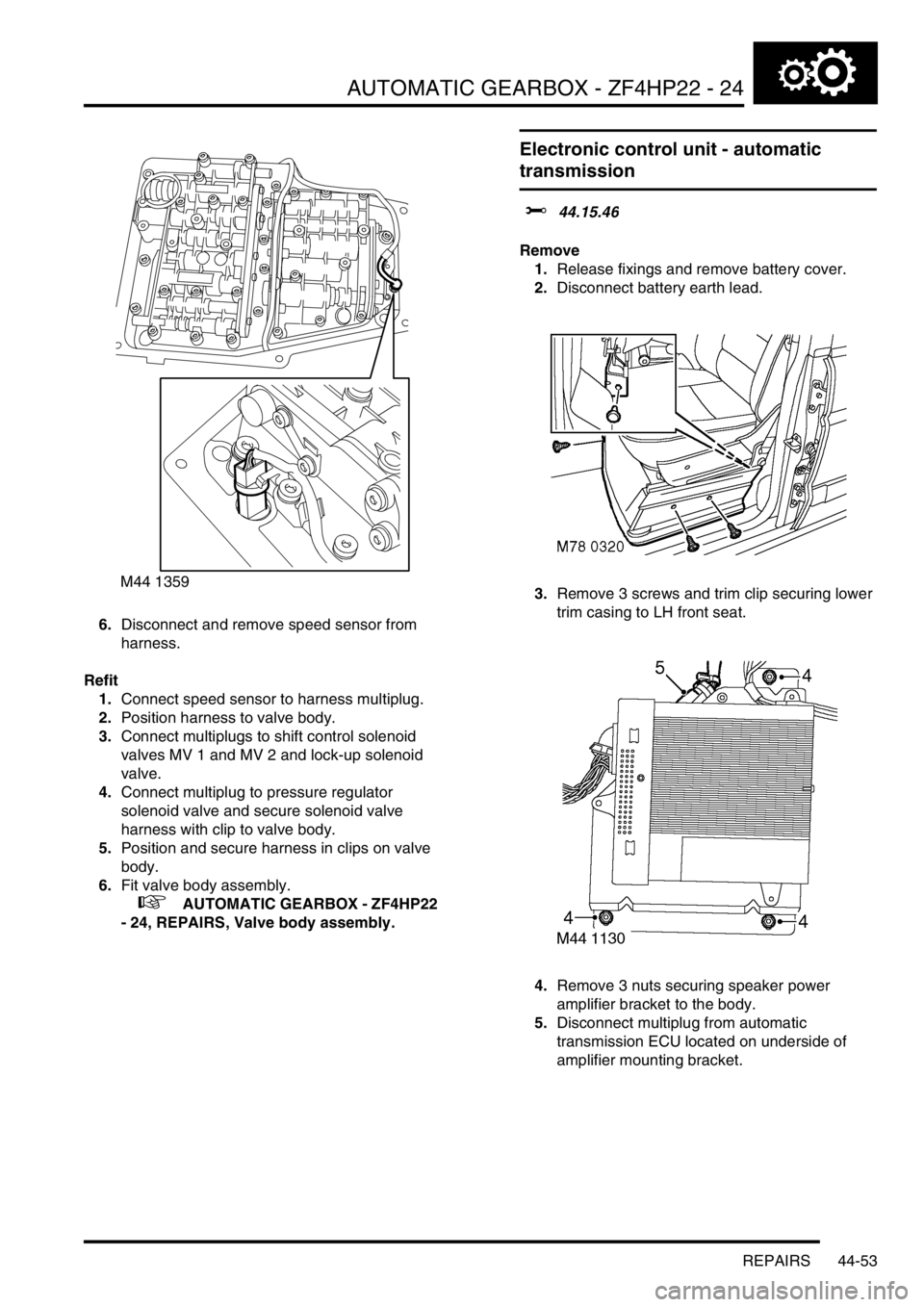
6.Disconnect and remove speed sensor from
harness.
Refit
1.Connect speed sensor to harness multiplug.
2.Position harness to valve body.
3.Connect multiplugs to shift control solenoid
valves MV 1 and MV 2 and lock-up solenoid
valve.
4.Connect multiplug to pressure regulator
solenoid valve and secure solenoid valve
harness with clip to valve body.
5.Position and secure harness in clips on valve
body.
6.Fit valve body assembly.
+ AUTOMATIC GEARBOX - ZF4HP22
- 24, REPAIRS, Valve body assembly.
Electronic control unit - automatic
transmission
$% 44.15.46
Remove
1.Release fixings and remove battery cover.
2.Disconnect battery earth lead.
3.Remove 3 screws and trim clip securing lower
trim casing to LH front seat.
4.Remove 3 nuts securing speaker power
amplifier bracket to the body.
5.Disconnect multiplug from automatic
transmission ECU located on underside of
amplifier mounting bracket.
M44 1359
Page 851 of 1672

AUTOMATIC GEARBOX - ZF4HP22 - 24
44-54 REPAIRS
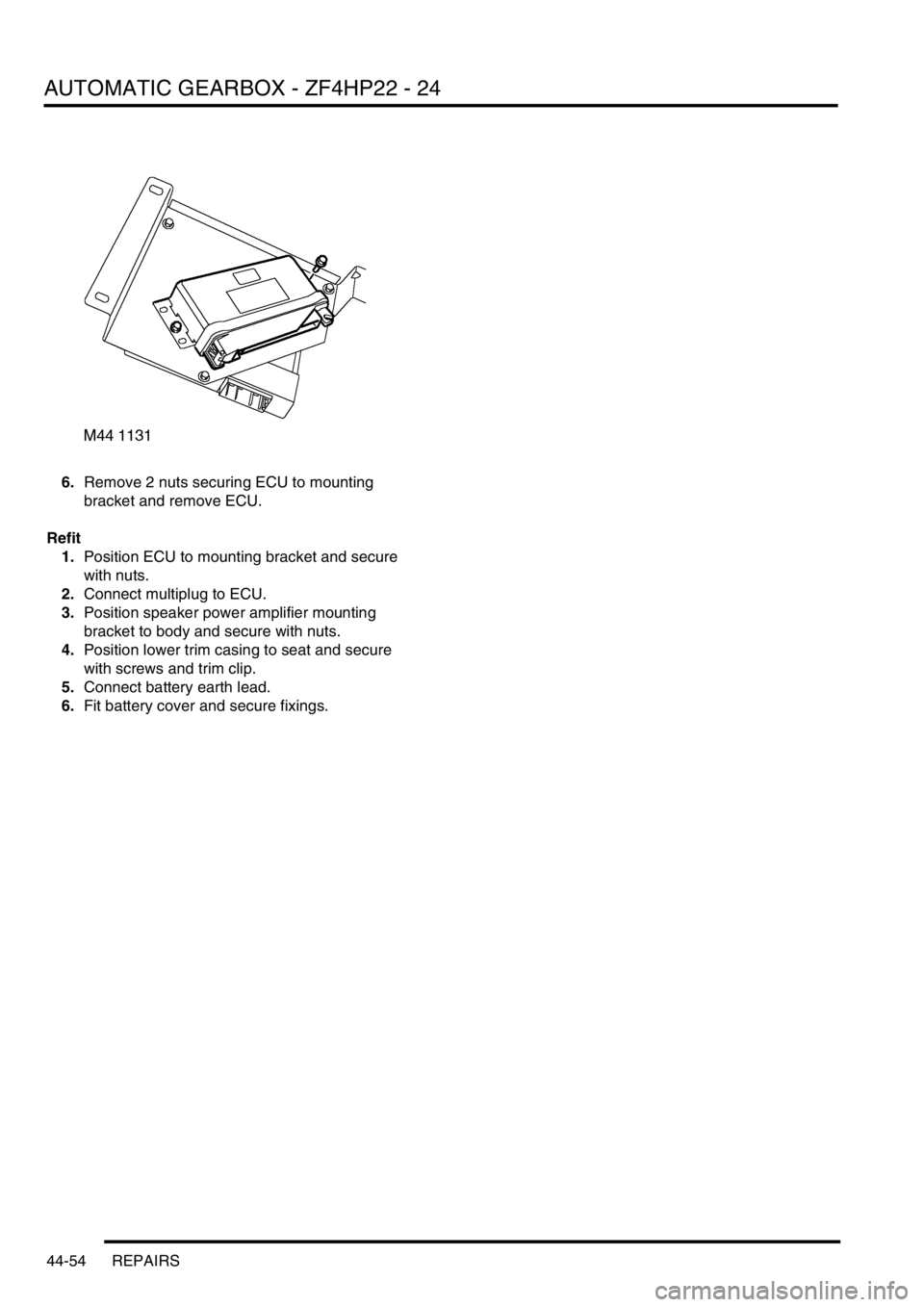
6.Remove 2 nuts securing ECU to mounting
bracket and remove ECU.
Refit
1.Position ECU to mounting bracket and secure
with nuts.
2.Connect multiplug to ECU.
3.Position speaker power amplifier mounting
bracket to body and secure with nuts.
4.Position lower trim casing to seat and secure
with screws and trim clip.
5.Connect battery earth lead.
6.Fit battery cover and secure fixings.
Page 856 of 1672

PROPELLER SHAFTS
REPAIRS 47-5
REPAIRS
Propeller shaft - front
$% 47.15.02
Remove
1.Raise front of vehicle.
WARNING: Do not work on or under a
vehicle supported only by a jack. Always
support the vehicle on safety stands.
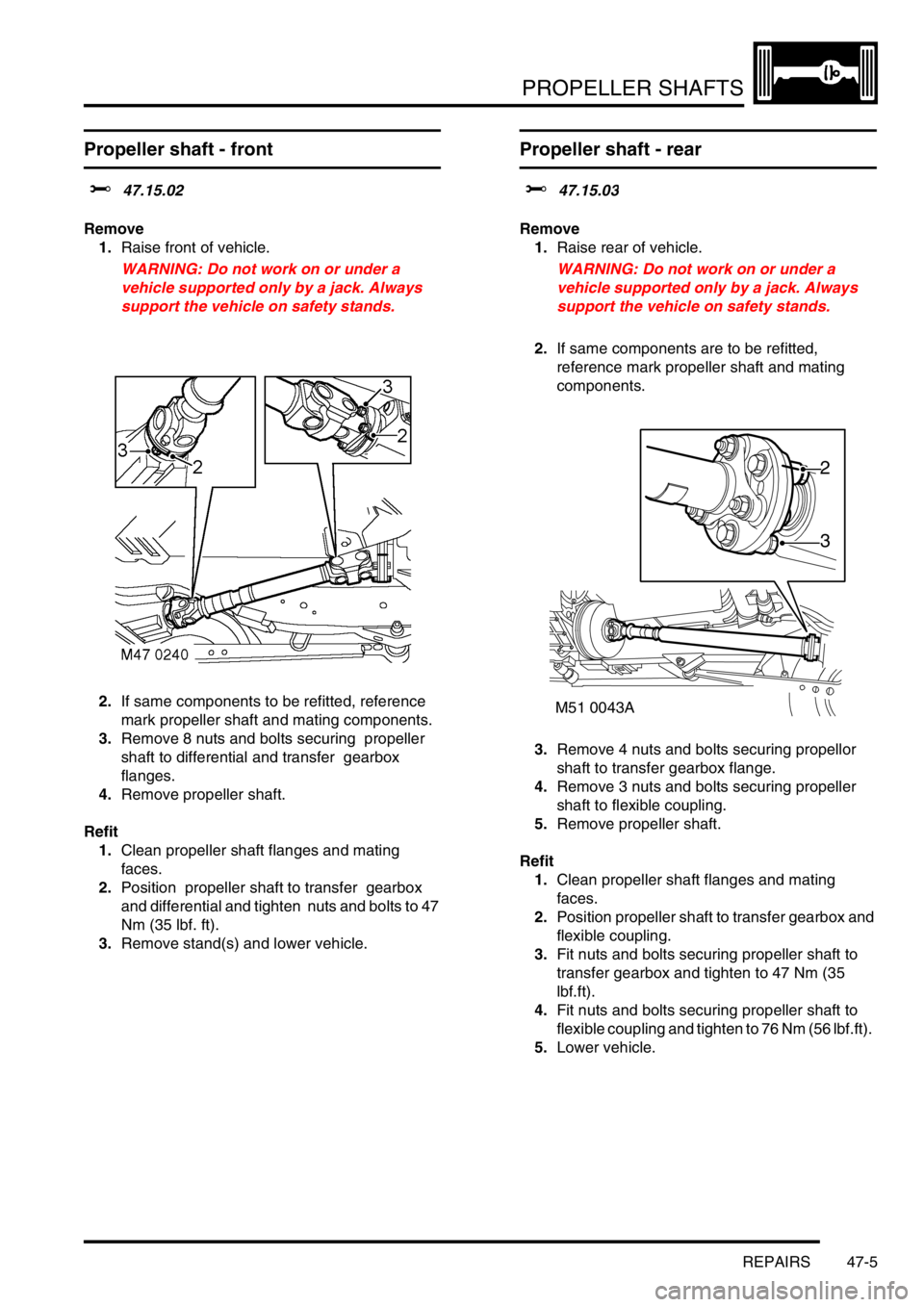
2.If same components to be refitted, reference
mark propeller shaft and mating components.
3.Remove 8 nuts and bolts securing propeller
shaft to differential and transfer gearbox
flanges.
4.Remove propeller shaft.
Refit
1.Clean propeller shaft flanges and mating
faces.
2.Position propeller shaft to transfer gearbox
and differential and tighten nuts and bolts to 47
Nm (35 lbf. ft).
3.Remove stand(s) and lower vehicle.
Propeller shaft - rear
$% 47.15.03
Remove
1.Raise rear of vehicle.
WARNING: Do not work on or under a
vehicle supported only by a jack. Always
support the vehicle on safety stands.
2.If same components are to be refitted,
reference mark propeller shaft and mating
components.
3.Remove 4 nuts and bolts securing propellor
shaft to transfer gearbox flange.
4.Remove 3 nuts and bolts securing propeller
shaft to flexible coupling.
5.Remove propeller shaft.
Refit
1.Clean propeller shaft flanges and mating
faces.
2.Position propeller shaft to transfer gearbox and
flexible coupling.
3.Fit nuts and bolts securing propeller shaft to
transfer gearbox and tighten to 47 Nm (35
lbf.ft).
4.Fit nuts and bolts securing propeller shaft to
flexible coupling and tighten to 76 Nm (56 lbf.ft).
5.Lower vehicle.
M51 0043A
2
3
Page 857 of 1672

PROPELLER SHAFTS
47-6 REPAIRS
Flexible coupling
$% 47.20.08
Remove
1.Raise rear of vehicle.
WARNING: Do not work on or under a
vehicle supported only by a jack. Always
support the vehicle on safety stands.
2.If same components to be refitted, reference
mark flexible coupling and mating components.
3.Remove 3 nuts and bolts securing propeller
shaft to flexible coupling.
4.Move propeller shaft forwards to release from
flexible coupling and differential drive flange
spigot.
5.Tie propeller shaft aside.
6.Remove 3 nuts and bolts securing flexible
coupling to differential drive flange and remove
flexible coupling.Refit
1.Ensure flexible coupling, spigot and drive
flanges are clean.
2.Align the arrows on the flexible coupling with
the securing bolt positions as illustrated. Fit
flexible coupling to differential drive flange and
tighten nuts and bolts to 76 Nm (56 lbf.ft).
3.Fit propeller shaft to spigot and flexible
coupling. Tighten nuts and bolts to 76 Nm (56
lbf.ft).
4.Remove stand(s) and lower vehicle.
Page 861 of 1672

REAR AXLE
51-2 DESCRIPTION AND OPERATION
Description
General
The rear axle consists of an axle casing with a differential unit attached to the right of the vehicle centre line. A wheel
hub is installed in each end of the axle casing and connected to the differential unit by a drive shaft.
Axle casing
The axle casing is of welded construction, with brackets on the casing exterior for attachment to the rear suspension.
A differential cover on the rear of the axle casing contains an oil level plug for checking and replenishment of the
differential unit lubricating oil. A magnetic drain plug is installed on the underside of the axle casing.
The interior of the axle casing is ventilated through a breather tube inserted in a red plastic sleeve in the top of the
casing. The open end of the breather tube is located between the chassis and the left rear wheelarch.
Differential unit
The differential unit is of the spiral bevel type, lubricated by splash oil. The unit consists of a differential carrier
attached to a pinion housing. In the pinion housing, the pinion is splined to a pinion flange which is secured with a bolt
and washer. An oil seal prevents leakage past the pinion flange.
Centralising peg
The centralising peg is a press fit in the centre of the pinion flange and provides a positive location for the rear
propellor shaft to ensure it is centralised with the flange.