ECU LAND ROVER DISCOVERY 2002 Owner's Guide
[x] Cancel search | Manufacturer: LAND ROVER, Model Year: 2002, Model line: DISCOVERY, Model: LAND ROVER DISCOVERY 2002Pages: 1672, PDF Size: 46.1 MB
Page 129 of 1672
MAINTENANCE
10-20 PROCEDURES
5.Apply recommended grease to the grease
nipple.
+ CAPACITIES, FLUIDS AND
LUBRICANTS, Lubrication.
6.Remove grease nipple.
7.Fit blanking plug.
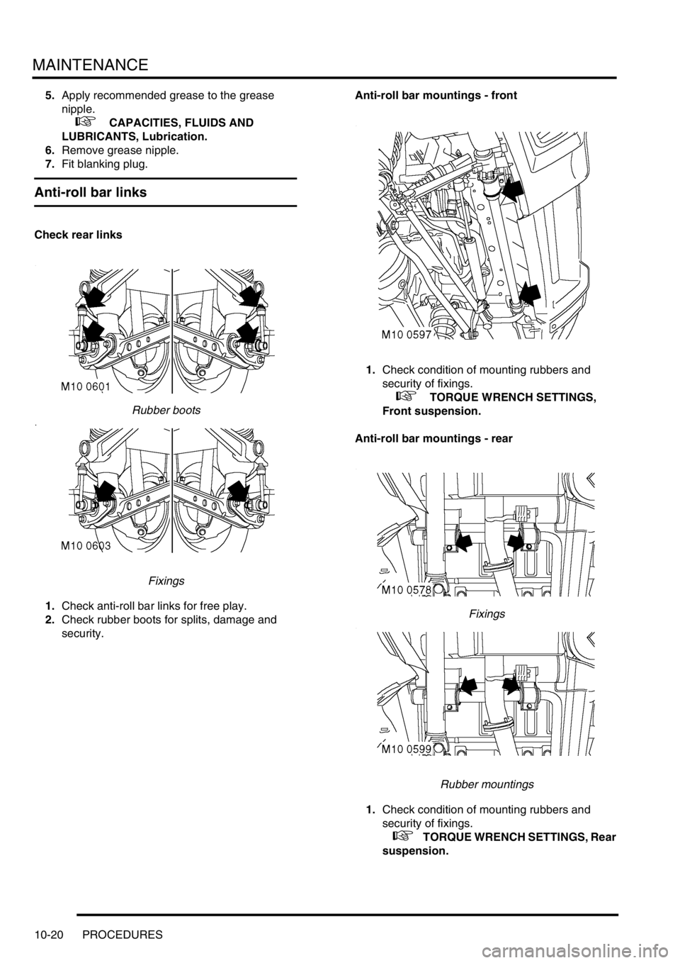
Anti-roll bar links
Check rear links
Rubber boots
Fixings
1.Check anti-roll bar links for free play.
2.Check rubber boots for splits, damage and
security.Anti-roll bar mountings - front
1.Check condition of mounting rubbers and
security of fixings.
+ TORQUE WRENCH SETTINGS,
Front suspension.
Anti-roll bar mountings - rear
Fixings
Rubber mountings
1.Check condition of mounting rubbers and
security of fixings.
+ TORQUE WRENCH SETTINGS, Rear
suspension.
Page 130 of 1672
MAINTENANCE
PROCEDURES 10-21
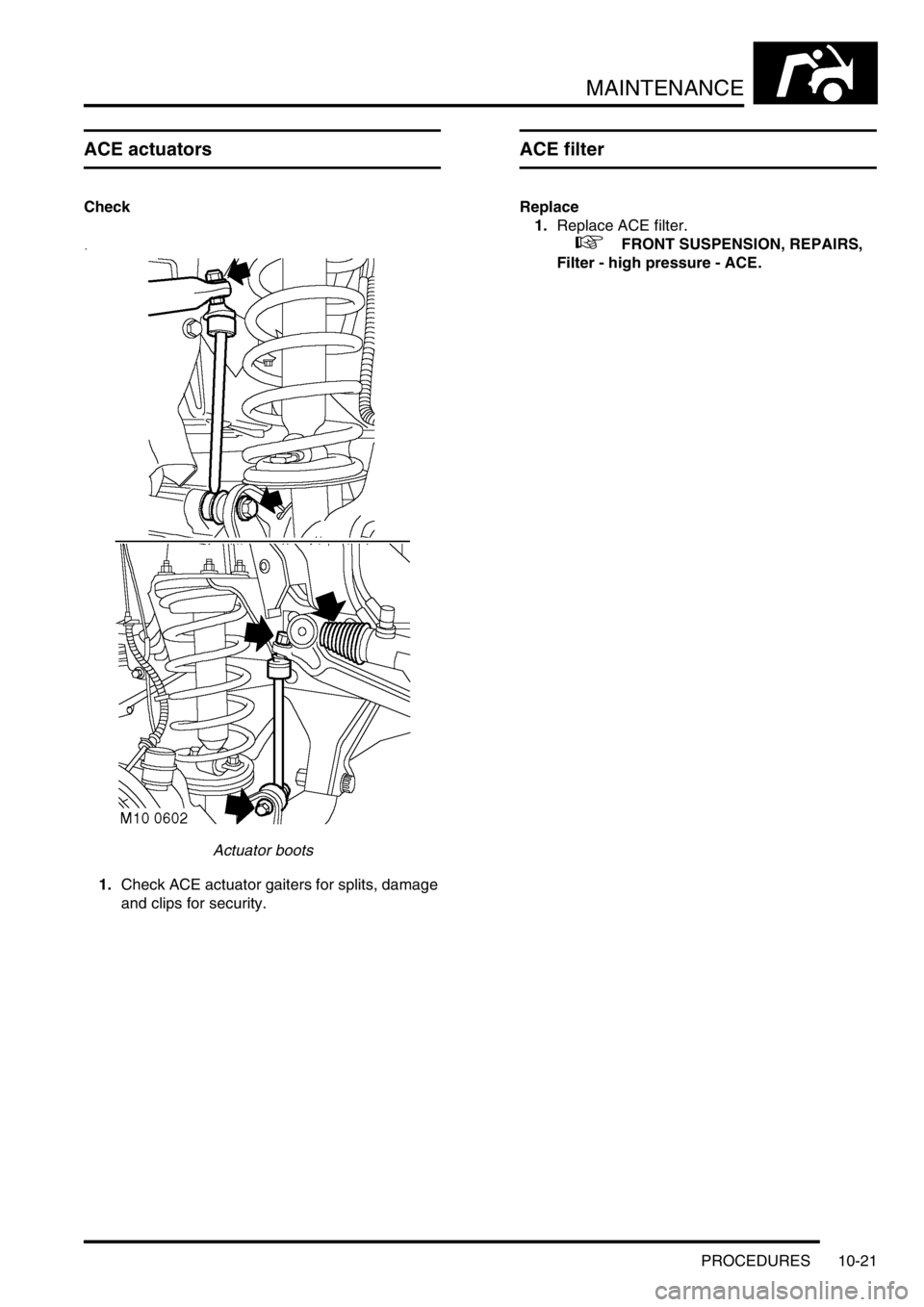
ACE actuators
Check
Actuator boots
1.Check ACE actuator gaiters for splits, damage
and clips for security.
ACE filter
Replace
1.Replace ACE filter.
+ FRONT SUSPENSION, REPAIRS,
Filter - high pressure - ACE.
Page 131 of 1672
MAINTENANCE
10-22 PROCEDURES
Brake hose, brake, fuel, ACE, clutch
pipes and unions/electrical harnesses
Check – General
1.Check brake servo hose for cracks, leaks and
chafing.
2.Check brake, clutch pipes and unions for
chafing, leaks and corrosion and that all pipes
and hoses are correctly routed and secure.
3.Check electrical harnesses for chafing and
damage.
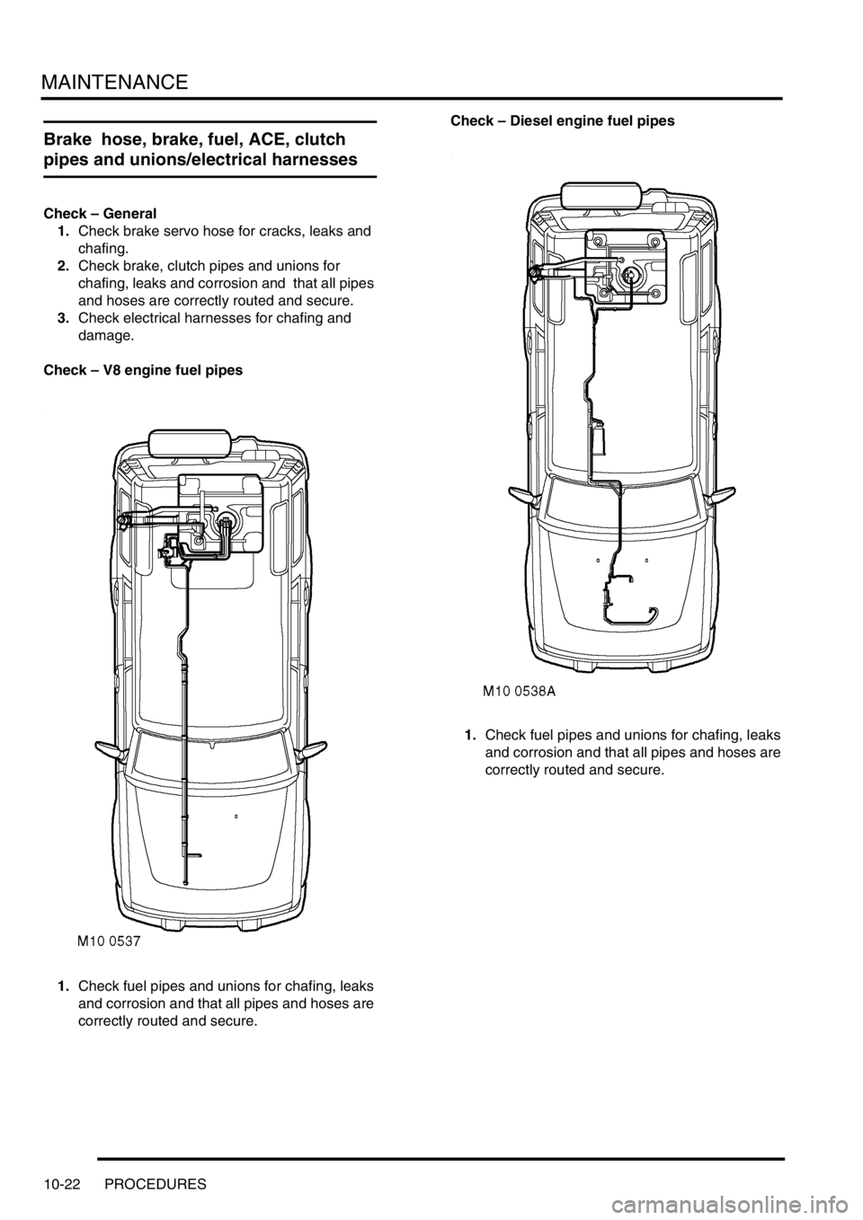
Check – V8 engine fuel pipes
1.Check fuel pipes and unions for chafing, leaks
and corrosion and that all pipes and hoses are
correctly routed and secure. Check – Diesel engine fuel pipes
1.Check fuel pipes and unions for chafing, leaks
and corrosion and that all pipes and hoses are
correctly routed and secure.
Page 132 of 1672
MAINTENANCE
PROCEDURES 10-23
Power steering, suspension
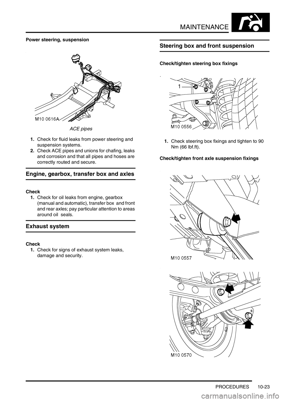
ACE pipes
1.Check for fluid leaks from power steering and
suspension systems.
2.Check ACE pipes and unions for chafing, leaks
and corrosion and that all pipes and hoses are
correctly routed and secure.
Engine, gearbox, transfer box and axles
Check
1.Check for oil leaks from engine, gearbox
(manual and automatic), transfer box and front
and rear axles; pay particular attention to areas
around oil seals.
Exhaust system
Check
1.Check for signs of exhaust system leaks,
damage and security.
Steering box and front suspension
Check/tighten steering box fixings
1.Check steering box fixings and tighten to 90
Nm (66 lbf.ft).
Check/tighten front axle suspension fixings
Page 134 of 1672
MAINTENANCE
PROCEDURES 10-25
1.Check and tighten if necessary all rear axle
suspension fixings.
+ TORQUE WRENCH SETTINGS, Rear
suspension.
Steering rod ball joints
Check
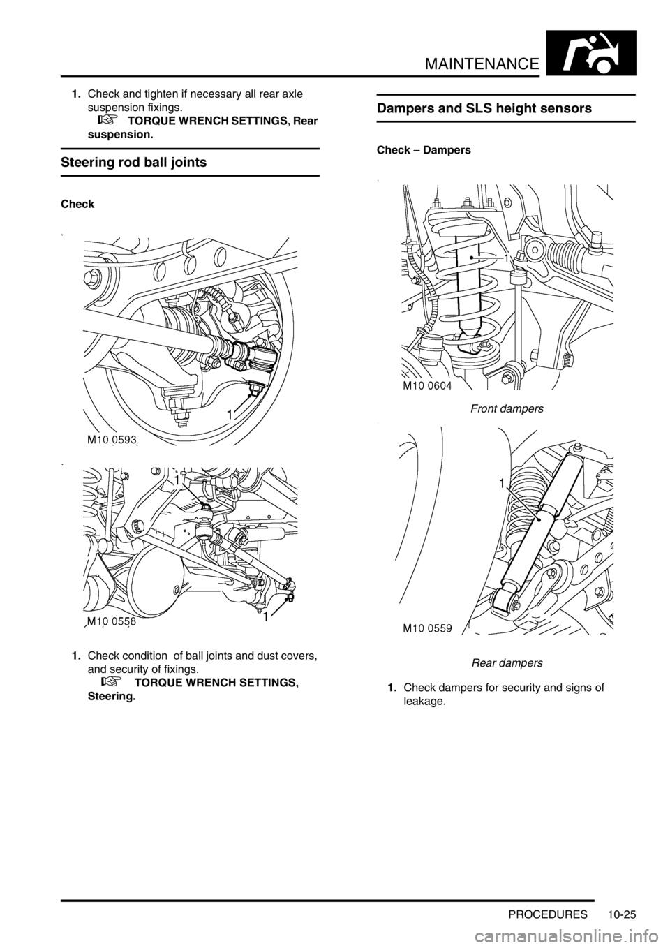
1.Check condition of ball joints and dust covers,
and security of fixings.
+ TORQUE WRENCH SETTINGS,
Steering.
Dampers and SLS height sensors
Check – Dampers
Front dampers
Rear dampers
1.Check dampers for security and signs of
leakage.
Page 135 of 1672
MAINTENANCE
10-26 PROCEDURES
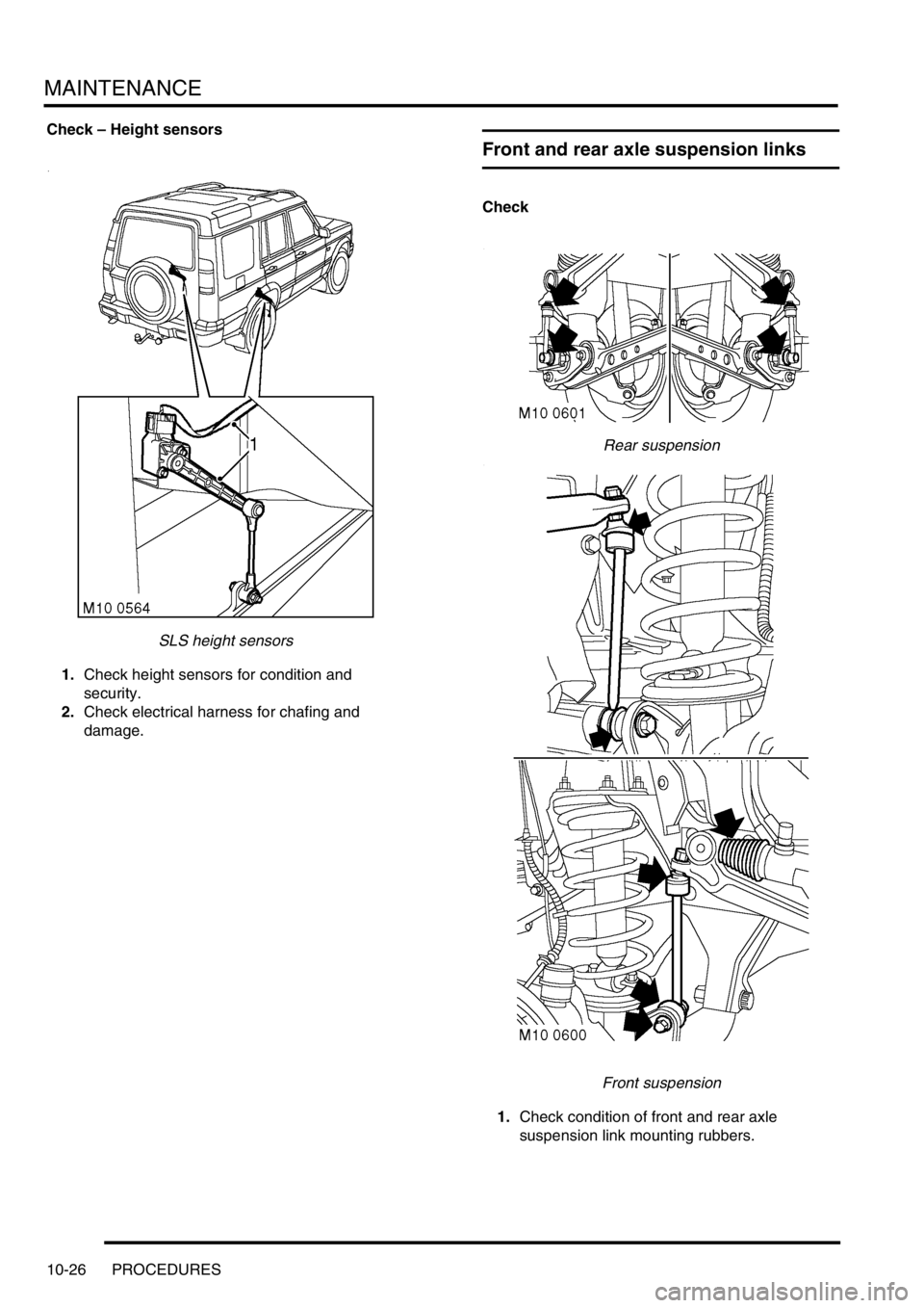
Check – Height sensors
SLS height sensors
1.Check height sensors for condition and
security.
2.Check electrical harness for chafing and
damage.
Front and rear axle suspension links
Check
Rear suspension
Front suspension
1.Check condition of front and rear axle
suspension link mounting rubbers.
Page 136 of 1672
MAINTENANCE
PROCEDURES 10-27
2.Check security of fixings.
+ TORQUE WRENCH SETTINGS,
Front suspension.
+ TORQUE WRENCH SETTINGS, Rear
suspension.
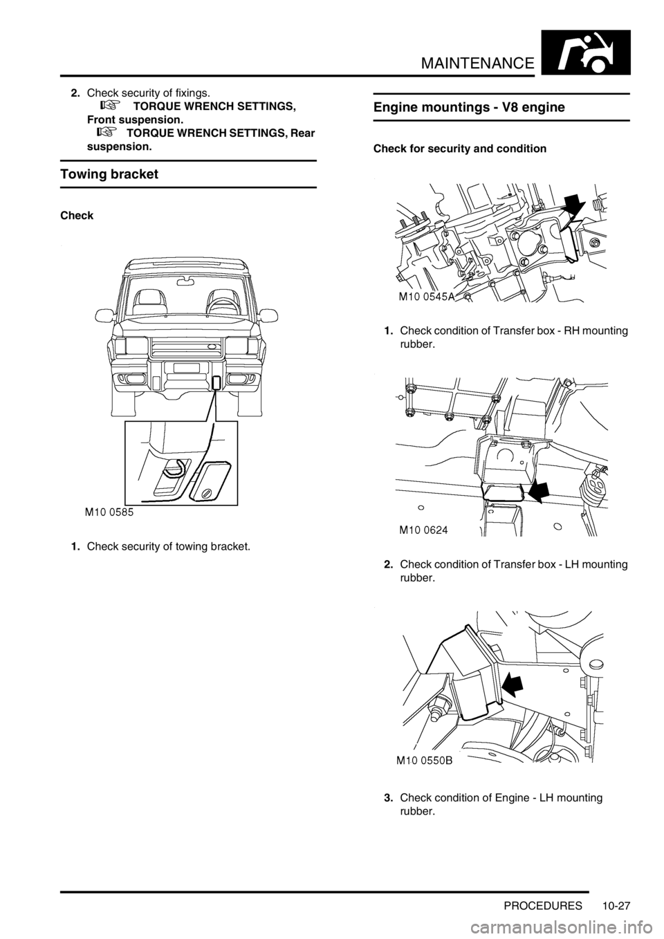
Towing bracket
Check
1.Check security of towing bracket.
Engine mountings - V8 engine
Check for security and condition
1.Check condition of Transfer box - RH mounting
rubber.
2.Check condition of Transfer box - LH mounting
rubber.
3.Check condition of Engine - LH mounting
rubber.
Page 158 of 1672
ENGINE - TD5
DESCRIPTION AND OPERATION 12-1-19
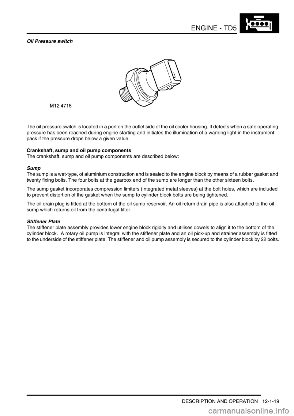
Oil Pressure switch
The oil pressure switch is located in a port on the outlet side of the oil cooler housing. It detects when a safe operating
pressure has been reached during engine starting and initiates the illumination of a warning light in the instrument
pack if the pressure drops below a given value.
Crankshaft, sump and oil pump components
The crankshaft, sump and oil pump components are described below:
Sump
The sump is a wet-type, of aluminium construction and is sealed to the engine block by means of a rubber gasket and
twenty fixing bolts. The four bolts at the gearbox end of the sump are longer than the other sixteen bolts.
The sump gasket incorporates compression limiters (integrated metal sleeves) at the bolt holes, which are included
to prevent distortion of the gasket when the sump to cylinder block bolts are being tightened.
The oil drain plug is fitted at the bottom of the oil sump reservoir. An oil return drain pipe is also attached to the oil
sump which returns oil from the centrifugal filter.
Stiffener Plate
The stiffener plate assembly provides lower engine block rigidity and utilises dowels to align it to the bottom of the
cylinder block. A rotary oil pump is integral with the stiffener plate and an oil pick-up and strainer assembly is fitted
to the underside of the stiffener plate. The stiffener and oil pump assembly is secured to the cylinder block by 22 bolts.
Page 161 of 1672
ENGINE - TD5
12-1-22 DESCRIPTION AND OPERATION
The camshaft carrier and cylinder head assembly is attached to the cylinder block by twelve cylinder head retaining
bolts which pass through the camshaft carrier and the cylinder head to secure the assembly to the cylinder block.
CAUTION: The valve heads, tips of the injectors and glow plugs protrude below the face of the cylinder head
and will be damaged if the cylinder head is stored face down.
The camshaft is located between the cylinder head and the camshaft carrier, and the bearing journals are line bored
between the two components to form a matched pair.
CAUTION: Always fit plugs to open connections to prevent contamination.
The valve guides and valve seat inserts are sintered components which are interference fit to the cylinder head. The
cylinder head machining also provide the locations for the electronic unit injectors, glow plugs, hydraulic lash
adjusters, finger followers and low pressure fuel rail.
Cooling to the cylinder head is provided by coolant flow through a water jacket machined into the cylinder head.
Drillings through the block provide lubrication channels for pressurised oil supply to cylinder head components such
as the lash adjusters, finger followers, rocker arms and camshaft bearings.
A coolant outlet elbow is fitted to the front LH side of the cylinder head to allow flow of coolant from the cylinder head
back to the radiator. A metal gasket is used to seal the joint between the water outlet elbow and the cylinder head. A
coolant temperature sensor is located in a port in the side of the water outlet elbow for monitoring coolant temperature.
A stub pipe is connected at the front RH side of the cylinder block above the timing cover which connects a pipe to
supply oil to the vacuum pump. The timing chain tensioner adjuster is screwed in a thread in the cylinder head at a
location on the front RH side of the engine below the oil feed port for the vacuum pump.
An access hole for the camshaft gear is included at the front of the cylinder head which is sealed with a plastic plug
and rubber 'O'-ring. A press-fit core plug for the chain chest is located on the front face of the cylinder head.
A press-fit core plug for the cylinder head water jacket is located at the rear of the cylinder head and a threaded brass
plug for the water jacket is located on the LH side of the cylinder head beneath the exhaust manifold assembly.
Page 162 of 1672
ENGINE - TD5
DESCRIPTION AND OPERATION 12-1-23
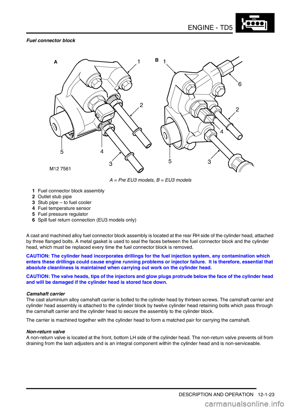
Fuel connector block
A = Pre EU3 models, B = EU3 models
1Fuel connector block assembly
2Outlet stub pipe
3Stub pipe – to fuel cooler
4Fuel temperature sensor
5Fuel pressure regulator
6Spill fuel return connection (EU3 models only)
A cast and machined alloy fuel connector block assembly is located at the rear RH side of the cylinder head, attached
by three flanged bolts. A metal gasket is used to seal the faces between the fuel connector block and the cylinder
head, which must be replaced every time the fuel connector block is removed.
CAUTION: The cylinder head incorporates drillings for the fuel injection system, any contamination which
enters these drillings could cause engine running problems or injector failure. It is therefore, essential that
absolute cleanliness is maintained when carrying out work on the cylinder head.
CAUTION: The valve heads, tips of the injectors and glow plugs protrude below the face of the cylinder head
and will be damaged if the cylinder head is stored face down.
Camshaft carrier
The cast aluminium alloy camshaft carrier is bolted to the cylinder head by thirteen screws. The camshaft carrier and
cylinder head assembly is attached to the cylinder block by twelve cylinder head retaining bolts which pass through
the camshaft carrier and the cylinder head to secure the assembly to the cylinder block.
The carrier is machined together with the cylinder head to form a matched pair for carrying the camshaft.
Non-return valve
A non-return valve is located at the front, bottom LH side of the cylinder head. The non-return valve prevents oil from
draining from the lash adjusters and is an integral component within the cylinder head and is non-serviceable.