headlamp LAND ROVER DISCOVERY 2002 Repair Manual
[x] Cancel search | Manufacturer: LAND ROVER, Model Year: 2002, Model line: DISCOVERY, Model: LAND ROVER DISCOVERY 2002Pages: 1672, PDF Size: 46.1 MB
Page 1505 of 1672

BODY CONTROL UNIT
86-3-36 DESCRIPTION AND OPERATION
Key-in warning
The BCU can be programmed to one of two options:
lOption 1 – no timeout.
lOption 2 – no key-in warning.
The BCU issues an audible warning No. 2 request, depending on the status of the following inputs:
lIgnition state.
lIgnition key inserted.
lDriver's door open.
If the key-in warning is programmed into the BCU for operation, audible warning No.2 will be requested if the ignition
switch is off, the ignition key inserted signal is on and the driver's door open signal is ON.
In the event of a communications link failure occurring, the audible warning request is not sent to the instrument pack.
SLABS HDC warning
The BCU issues an audible warning No. 3 request, depending on the status of the following inputs:
lIgnition state.
lSLABS HDC warning.
The SLABS warning transmitted by the SLABS ECU is a 2 Hz signal, audible warning No. 3 is requested on every
falling edge of this signal. If the signal from the SLABS ECU stays low for more than 650 ms, audible warning No. 3
is requested every 2 seconds, for 30 seconds, while the signal stays low.
In the event of a communications link failure occurring, the audible warning request is not sent to the instrument pack.
Transfer box in neutral warning
If the transfer box is in the neutral position and the ignition switch is on, the BCU issues an audible warning No. 4
request. The BCU checks for the following inputs:
lTransfer box neutral selected.
lIgnition on.
The transfer box in neutral warning is activated by communicating with the instrument pack via the serial datalink. If
a communications link failure occurs while the transfer box in neutral warning is active, the audible warning will not
operate.
Lights on warning
If the ignition switch is off while the side lamps or headlamps on and the driver's door is opened, the BCU issues an
audible warning No. 5 request.
The BCU checks for the following inputs:
lDriver's door open.
lIgnition on.
lSide lamps.
lDipped beam state.
lMain beam state.
The lights on warning is activated by communicating with the instrument pack via the serial datalink. If a
communications link failure occurs while the lights on warning is active, the audible warning will not operate.
Page 1544 of 1672

WINDOWS
DESCRIPTION AND OPERATION 86-5-5
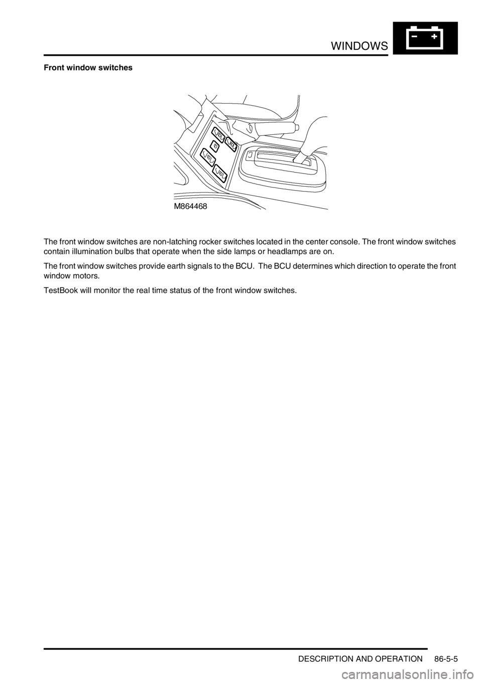
Front window switches
The front window switches are non-latching rocker switches located in the center console. The front window switches
contain illumination bulbs that operate when the side lamps or headlamps are on.
The front window switches provide earth signals to the BCU. The BCU determines which direction to operate the front
window motors.
TestBook will monitor the real time status of the front window switches.
Page 1588 of 1672

HARNESSES
REPAIRS 86-7-17
9.Disconnect multiplugs from cooling fan and
horn.
10.Release 3 cable tie clips from front RH panel.
11.Remove RH indicator lamp.
+ LIGHTING, REPAIRS, Lamp - front
repeater.12.Disconnect multiplugs from headlamp and
sidelamp.
13.Disconnect multiplug from headlamp levelling
motor.
Page 1591 of 1672

HARNESSES
86-7-20 REPAIRS
34.Release multiplug from ACE accelerometer.
35.Remove 3 cable tie clips from body and
withdraw harness to bulkhead.
36.Disconnect multiplug from LH horn.
37.Remove LH indicator lamp.
+ LIGHTING, REPAIRS, Lamp - front
repeater. 38.Disconnect multiplugs from headlamp and
sidelamp.
39.Disconnect headlamp level multiplug from
headlamp levelling motor.
40.Release earth header behind headlamp.
41.Disconnect multiplug from front of washer
reservoir.
42.Release clip securing fog lamp multiplug.
Page 1599 of 1672

HARNESSES
86-7-28 REPAIRS
18.Secure multiplugs to steering column support
bracket and connect brake and clutch pedal
multiplugs.
19.Connect multiplugs to column switch and
passive coil.
20.Position passenger compartment fusebox,
connect multiplugs, fit fusebox to fascia and
secure with nut.
21.Connect ignition switch multiplug to fuse box.
22.With assistance feed LH side of harness into
engine bay.
23.Connect multiplugs to front door harness and
body harness.
24.Position earth headers to LH lower 'A' post and
secure with nuts.
25.Connect multiplugs to ECU pack.
26.Position harness in engine bay.
27.Connect and secure heated front screen
multiplugs.
28.Fit plenum molding.
+ HEATING AND VENTILATION,
REPAIRS, Plenum Air Intake.
29.Connect multiplugs to ABS sensor and fuel
cut-off switch.
30.Using draw string feed harness through inner
wing, remove draw string, connect repeater
lamp multiplug and fit lamp.
31.Connect multiplugs to ABS modulator.
32.Feed harness through to front panel.
33.Position body earth leads and secure with
bolts.
34.Connect washer reservoir multiplugs and
pipes, secure pipes with clips.
35.Secure fog lamp multiplug.
36.Secure earth header behind headlamp.
37.Connect multiplugs to headlamp level motor,
headlamp and side lamp.
38.Fit indicator lamp
+ LIGHTING, REPAIRS, Lamp - front
repeater.
39.Connect multiplug to LH horn.
40.Feed harness to ACE accelerometer, connect
multiplug and secure with cable ties.
41.Connect cruise control, ABS sensor and brake
fluid level switch multiplugs.
42.Connect engine harness multiplug and feed
harness along RH wing to fuse box.
43.Using draw string pull harness through inner
wing, remove draw string, connect repeater
lamp multiplug and fit lamp. 44.Connect chassis harness multiplugs.
45.Position engine bay fuse box and connect
multiplugs, fit fuse box and secure with screws.
46.Connect multiplugs to front of fuse box.
47.Position battery and starter cables and secure
with screws.
48.Fit fuse box cover.
49.Position earth lead and secure with nut.
50.Feed harness through to front panel.
51.Secure fog lamp multiplug.
52.Connect headlamp level motor, headlamp and
side lamp multiplugs.
53.Fit indicator lamp.
+ LIGHTING, REPAIRS, Lamp - front
repeater.
54.Secure harness to RH front panel.
55.Connect cooling fan and horn multiplug.
56.Secure harness to lower support rail.
57.Connect receiver drier and air temperature
sensor multiplugs.
58.Fit front bumper.
+ EXTERIOR FITTINGS, REPAIRS,
Bumper assembly - front.
59.Fit battery tray.
60.Fit air filter assembly.
+ ENGINE MANAGEMENT SYSTEM -
V8, REPAIRS, Air cleaner assembly.
61.Position both lower 'A' post trims and secure
with studs.
62.Fit heater assembly.
+ HEATING AND VENTILATION,
REPAIRS, Heater assembly - models with
air conditioning.
+ HEATING AND VENTILATION,
REPAIRS, Heater assembly - models
without air conditioning.
Page 1644 of 1672

INSTRUMENTS
DESCRIPTION AND OPERATION 88-17
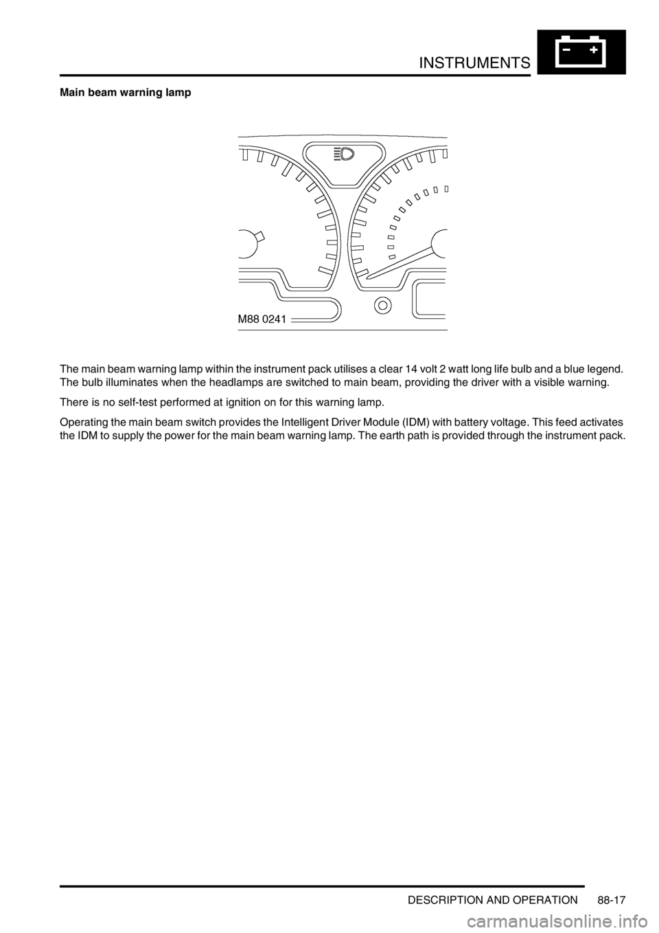
Main beam warning lamp
The main beam warning lamp within the instrument pack utilises a clear 14 volt 2 watt long life bulb and a blue legend.
The bulb illuminates when the headlamps are switched to main beam, providing the driver with a visible warning.
There is no self-test performed at ignition on for this warning lamp.
Operating the main beam switch provides the Intelligent Driver Module (IDM) with battery voltage. This feed activates
the IDM to supply the power for the main beam warning lamp. The earth path is provided through the instrument pack.