ECU LAND ROVER DISCOVERY 2002 Manual Online
[x] Cancel search | Manufacturer: LAND ROVER, Model Year: 2002, Model line: DISCOVERY, Model: LAND ROVER DISCOVERY 2002Pages: 1672, PDF Size: 46.1 MB
Page 232 of 1672

ENGINE - TD5
OVERHAUL 12-1-93
Timing chain and sprockets
$% 12.65.13.01
Disassembly
1.Remove cylinder head gasket.
+ ENGINE - Td5, OVERHAUL, Gasket
- cylinder head.
CAUTION: If timing chain tensioner is to be
replaced, ensure tensioner is correct for
engine. Tensioner bodies are colour coded
as follows: Engine Serial No. Prefixes 10P to
14P – BLACK with, additionally on later
engines, YELLOW on tensioner hex. head.
Serial No. Prefixes 15P to 19P – body is
colour coded YELLOW. Later tensioners
may be fitted to early engines provided that
the modified adjustable guide is also fitted.
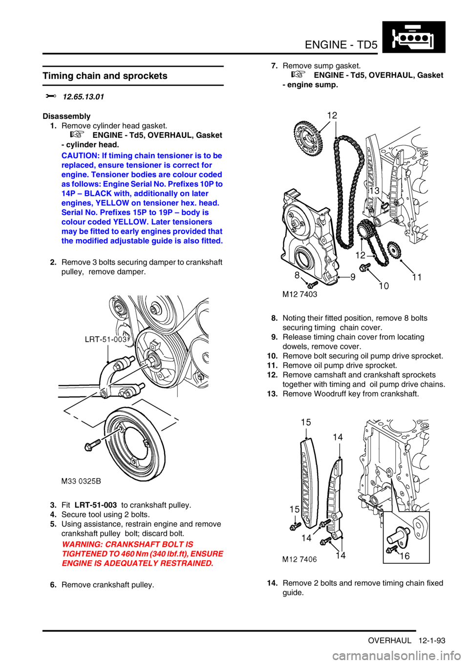
2.Remove 3 bolts securing damper to crankshaft
pulley, remove damper.
3.Fit LRT-51-003 to crankshaft pulley.
4.Secure tool using 2 bolts.
5.Using assistance, restrain engine and remove
crankshaft pulley bolt; discard bolt.
WARNING: CRANKSHAFT BOLT IS
TIGHTENED TO 460 Nm (340 lbf.ft), ENSURE
ENGINE IS ADEQUATELY RESTRAINED.
6.Remove crankshaft pulley.7.Remove sump gasket.
+ ENGINE - Td5, OVERHAUL, Gasket
- engine sump.
8.Noting their fitted position, remove 8 bolts
securing timing chain cover.
9.Release timing chain cover from locating
dowels, remove cover.
10.Remove bolt securing oil pump drive sprocket.
11.Remove oil pump drive sprocket.
12.Remove camshaft and crankshaft sprockets
together with timing and oil pump drive chains.
13.Remove Woodruff key from crankshaft.
14.Remove 2 bolts and remove timing chain fixed
guide.
Page 235 of 1672

ENGINE - TD5
12-1-96 OVERHAUL
27.Fit tool LRT-51-003 to crankshaft pulley,
secure with 2 bolts. Using assistance, restrain
engine and using a torque multiplier tighten
bolt to 450 Nm (340 lbf.ft).
WARNING: DUE TO THE HIGH TORQUE
LOADING REQUIRED, IT IS ESSENTIAL
THAT ENGINE IS ADEQUATELY
RESTRAINED.
28.Remove tool LRT-51-003.
29.Position damper to crankshaft pulley, fit 3 bolts
and tighten to 80 Nm (60 lbf.ft).
30.Fit sump gasket.
+ ENGINE - Td5, OVERHAUL, Gasket
- engine sump.
31.Fit cylinder head gasket.
+ ENGINE - Td5, OVERHAUL, Gasket
- cylinder head.
Bearings - connecting rods
$% 12.17.16.01
Disassembly
1.Remove oil pump.
+ ENGINE - Td5, OVERHAUL, Pump -
oil.
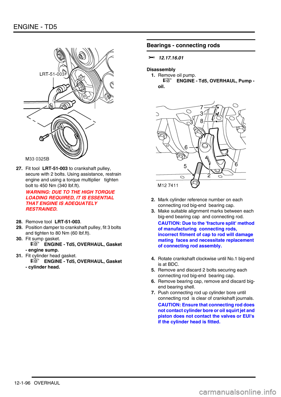
2.Mark cylinder reference number on each
connecting rod big-end bearing cap.
3.Make suitable alignment marks between each
big-end bearing cap and connecting rod.
CAUTION: Due to the 'fracture split' method
of manufacturing connecting rods,
incorrect fitment of cap to rod will damage
mating faces and necessitate replacement
of connecting rod assembly.
4.Rotate crankshaft clockwise until No.1 big-end
is at BDC.
5.Remove and discard 2 bolts securing each
connecting rod big-end bearing cap.
6.Remove bearing cap, remove and discard big-
end bearing shell.
7.Push connecting rod up cylinder bore until
connecting rod is clear of crankshaft journals.
CAUTION: Ensure that connecting rod does
not contact cylinder bore or oil squirt jet and
piston does not contact the valves or EUI's
if the cylinder head is fitted.
Page 237 of 1672

ENGINE - TD5
12-1-98 OVERHAUL
Pistons, connecting rods and cylinder
bores
$% 12.17.02.03
Disassembly
1.Remove cylinder head gasket.
+ ENGINE - Td5, OVERHAUL, Gasket
- cylinder head.
2.Remove connecting rod bearings.
+ ENGINE - Td5, OVERHAUL,
Bearings - connecting rods.
3.Remove ridge of carbon from top of cylinder
bore.
4.Suitably identify each piston and connecting
rod assembly to its respective cylinder bore.
5.Carefully push connecting rod to top of cylinder
bore taking care that connecting rod does not
contact oil squirt jet or cylinder wall; remove
each piston and connecting rod in turn.
6.Using a suitable expander, remove and discard
piston rings from pistons.
7.Clean carbon from piston crown and skirt. Do
not use abrasives on graphited area of
piston skirt, do not use a wire brush or
scraper on any part of pistons.
8.Secure connecting rod in a soft jawed vice.
9.Suitably identify each piston to its connecting
rod and fitted position of piston on rod.
10.Using suitable circlip pliers, remove and
discard 2 circlips securing gudgeon pin.
11.Push gudgeon pin out of piston and connecting
rod; remove piston.
12.Suitably identify each gudgeon pin to its
respective piston.
13.Repeat above procedures for remaining
pistons. Inspect
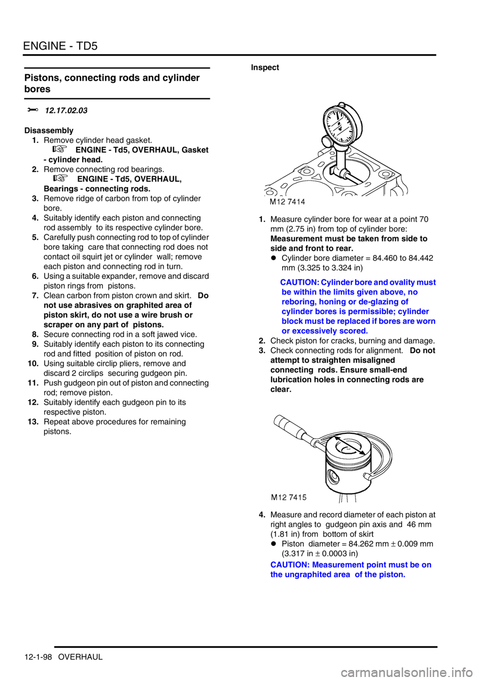
1.Measure cylinder bore for wear at a point 70
mm (2.75 in) from top of cylinder bore:
Measurement must be taken from side to
side and front to rear.
lCylinder bore diameter = 84.460 to 84.442
mm (3.325 to 3.324 in)
CAUTION: Cylinder bore and ovality must
be within the limits given above, no
reboring, honing or de-glazing of
cylinder bores is permissible; cylinder
block must be replaced if bores are worn
or excessively scored.
2.Check piston for cracks, burning and damage.
3.Check connecting rods for alignment. Do not
attempt to straighten misaligned
connecting rods. Ensure small-end
lubrication holes in connecting rods are
clear.
4.Measure and record diameter of each piston at
right angles to gudgeon pin axis and 46 mm
(1.81 in) from bottom of skirt
lPiston diameter = 84.262 mm
± 0.009 mm
(3.317 in
± 0.0003 in)
CAUTION: Measurement point must be on
the ungraphited area of the piston.
Page 239 of 1672

ENGINE - TD5
12-1-100 OVERHAUL
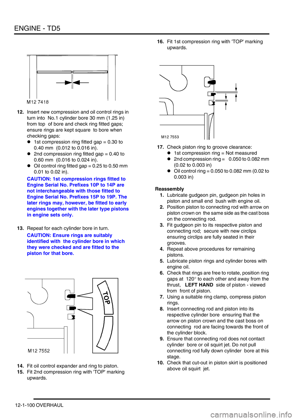
12.Insert new compression and oil control rings in
turn into No.1 cylinder bore 30 mm (1.25 in)
from top of bore and check ring fitted gaps;
ensure rings are kept square to bore when
checking gaps:
l1st compression ring fitted gap = 0.30 to
0.40 mm (0.012 to 0.016 in).
l2nd compression ring fitted gap = 0.40 to
0.60 mm (0.016 to 0.024 in).
lOil control ring fitted gap = 0.25 to 0.50 mm
0.01 to 0.02 in).
CAUTION: 1st compression rings fitted to
Engine Serial No. Prefixes 10P to 14P are
not interchangeable with those fitted to
Engine Serial No. Prefixes 15P to 19P. The
later rings may, however, be fitted to early
engines together with the later type pistons
in engine sets only.
13.Repeat for each cylinder bore in turn.
CAUTION: Ensure rings are suitably
identified with the cylinder bore in which
they were checked and are fitted to the
piston for that bore.
14.Fit oil control expander and ring to piston.
15.Fit 2nd compression ring with 'TOP' marking
upwards. 16.Fit 1st compression ring with 'TOP' marking
upwards.
17.Check piston ring to groove clearance:
l1st compression ring = Not measured
l2nd compression ring = 0.050 to 0.082 mm
(0.02 to 0.003 in)
lOil control ring = 0.050 to 0.082 mm (0.02 to
0.003 in)
Reassembly
1.Lubricate gudgeon pin, gudgeon pin holes in
piston and small end bush with engine oil.
2.Position piston to connecting rod with arrow on
piston crown on the same side as the cast boss
on the connecting rod.
3.Fit gudgeon pin to its respective piston and
connecting rod; secure with new circlips
ensuring circlips are fully seated in their
grooves.
4.Repeat above procedures for remaining
pistons.
5.Lubricate piston rings and cylinder bores with
engine oil.
6.Check that rings are free to rotate, position ring
gaps at 120
° to each other and away from the
thrust, LEFT HAND side of piston - viewed
from front of piston.
7.Using a suitable ring clamp, compress piston
rings.
8.Insert connecting rod and piston into its
respective cylinder bore ensuring that the
arrow on piston crown and the cast boss on
connecting rod are facing towards the front of
the cylinder block.
9.Ensure that connecting rod does not contact
cylinder bore or oil squirt jet. Do not pull
connecting rod fully down cylinder bore at this
stage.
10.Check that cut-out in piston skirt is positioned
above oil squirt jet.
Page 241 of 1672

ENGINE - TD5
12-1-102 OVERHAUL
Crankshaft
$% 12.21.33.01
Disassembly
1.Remove timing chain and sprockets.
+ ENGINE - Td5, OVERHAUL, Timing
chain and sprockets.
2.Remove crankshaft rear oil seal.
+ ENGINE - Td5, OVERHAUL, Seal -
crankshaft - rear - manual models.
3.Remove connecting rod bearings.
+ ENGINE - Td5, OVERHAUL,
Bearings - connecting rods.
4.Check that cylinder reference number is on
each main bearing cap and make alignment
marks between each main bearing cap and
cylinder block.
5.Starting at No.3 main bearing cap and working
outwards, progressively loosen, then remove 2
bolts securing each cap. Discard main bearing
cap bolts. 6.Fit 2 slave bolts into main bearing cap in turn
and ease bearing caps from cylinder block.
7.Remove and discard plain bearing shells from
each main bearing cap.
8.Using assistance, remove crankshaft.
9.Remove and discard grooved main bearing
shells and 2 thrust washers from cylinder
block.
10.Remove Torx screw securing each oil squirt jet
to cylinder block, remove squirt jets.
11.Clean main bearing shell and thrust washer
locations in cylinder block, ensure bolt holes
are clean and dry.
12.Clean main bearing caps.
13.Clean crankshaft bearing journals, check
oilways are clear.
14.Ensure drillings in oil squirt jets are clear.
Page 242 of 1672

ENGINE - TD5
OVERHAUL 12-1-103
15.Check core plugs in cylinder block for corrosion
or signs of leakage, seal replacement plugs
with Loctite 243.
Crankshaft - Inspection
1.Check crankshaft main and big-end bearings
for scoring, wear and ovality, make 3 checks at
120
° intervals in centre of journals.
lMain bearings = 62.0 mm
± 0.013 mm
(2.441 in
± 0.001 in).
lBig-end bearings = 54.000 mm
± 0.01 mm
(2.125 in
± 0.0004 in).
2. Crankshafts may not be reground, only one
size of main and big-end bearing shell is
available and if journals are found to be
scored, oval or worn, crankshaft must be
replaced. Main and big-end bearing shells
and thrust washers must be replaced
whenever they are removed.
3.Check crankshaft spigot bush for wear, replace
if necessary using the following procedures:
4.Secure crankshaft in a suitably padded vice.
5.Tap a thread in spigot bush to accommodate a
suitable impulse extractor.
6.Fit impulse extractor to spigot bush.
7.Remove spigot bush.
8.Clean spigot bush recess in crankshaft.
9.Fit new spigot bush to crankshaft using a
suitable mandrel. Reassembly
1.Fit oil squirt jets, fit Torx screws and tighten to
8 Nm (6 lbf.ft).
2.Lubricate new, grooved, main bearing shells
with engine oil and fit to cylinder block.
3.Lubricate new thrust washers with engine oil
and fit, grooved side facing outward, to recess
in each side of No.3 main bearing in cylinder
block.
4.Lubricate crankshaft journals with engine oil
and using assistance, position crankshaft in
cylinder block.
5.Lubricate new, plain, main bearing shells with
engine oil and fit to main bearing caps.
6.Fit main bearing caps in their original fitted
positions ensuring reference marks are
aligned.
7.Fit and lightly tighten new main bearing cap
bolts. Do not lubricate bolt threads.
8.Starting with No.3 main bearing cap and
working outwards, tighten main bearing cap
bolts to:
lStage 1 - 33 Nm (24 lbf.ft)
lStage 2 - Further 90
°
CAUTION: Do not carry out stages 1 and
2 in one operation.
9.Check that crankshaft rotates smoothly.
10. Attach a magnetic base DTI to front of cylinder
block with stylus of gauge on end of crankshaft.
Page 250 of 1672

ENGINE - V8
DESCRIPTION AND OPERATION 12-2-7
Oil sump
The oil sump is bolted to the bottom of the cylinder block and the timing cover and is sealed to both components with
a one piece gasket. A removable baffle to prevent oil surge is fitted in the sump. The oil pick-up pipe and strainer
assembly is positioned within the sump and is attached at the pick-up end to a stud screwed into number four main
bearing cap and at the delivery end to the oil pump. The oil drain plug is located in the bottom of the sump and is
sealed with a washer.
Pistons and connecting rods
Each of the aluminium alloy pistons has two compression rings and an oil control ring. The pistons are secured to the
connecting rods by semi-floating gudgeon pins. Each gudgeon pin is offset by 0.5 mm (0.02 in). The top of each piston
is recessed, the depth of recess determining the compression ratio of the engine. Plain, big-end bearing shells are
fitted to each connecting rod and cap.
Page 257 of 1672

ENGINE - V8
12-2-14 REPAIRS
Gasket - cylinder head - LH
$% 12.29.02
Remove
1.Remove inlet manifold gasket.
+ MANIFOLDS AND EXHAUST
SYSTEMS - V8, REPAIRS, Gasket - inlet
manifold - lower.
2.Noting their fitted order, disconnect ht leads
from spark plugs.
3.Remove bolt securing engine harness to rear
of cylinder head.
4. LH drive models: Remove brake servo heat
shield.
+ MANIFOLDS AND EXHAUST
SYSTEMS - V8, REPAIRS, Heat shield -
brake servo - Without Secondary Air
Injection.
5.Remove 8 bolts securing exhaust manifold to
cylinder head, release manifold and collect 2
gaskets.6.Progressively remove 4 bolts securing the
rocker shaft and remove rocker shaft.
7.Remove push rods. Store push rods in their
fitted order.
8. Models with SAI: Remove 2 air injection
adapters from cylinder head and discard.
9.In the sequence shown, remove 10 bolts
securing the cylinder head to block. Discard the
bolts.
Page 259 of 1672

ENGINE - V8
12-2-16 REPAIRS
17. LH drive models: Fit brake servo heat shield.
+ MANIFOLDS AND EXHAUST
SYSTEMS - V8, REPAIRS, Heat shield -
brake servo - Without Secondary Air
Injection.
18.Fit engine harness bolt and tighten to 22 Nm
(16 lbf.ft).
19.Connect ht leads to spark plugs in their correct
fitted order.
20.Fit inlet manifold gasket.
+ MANIFOLDS AND EXHAUST
SYSTEMS - V8, REPAIRS, Gasket - inlet
manifold - lower.
Gasket - cylinder head - RH
$% 12.29.03
Remove
1.Remove inlet manifold gasket.
+ MANIFOLDS AND EXHAUST
SYSTEMS - V8, REPAIRS, Gasket - inlet
manifold - lower.
2.Remove bolt securing auxiliary drive belt
tensioner and remove tensioner.
3.Remove 4 bolts securing alternator mounting
bracket and remove bracket.
4.Noting their fitted order, disconnect ht leads
from spark plugs.
5.Remove bolt securing engine earth lead.
Page 260 of 1672

ENGINE - V8
REPAIRS 12-2-17
6. RH drive models: Remove brake servo heat
shield.
+ MANIFOLDS AND EXHAUST
SYSTEMS - V8, REPAIRS, Heat shield -
brake servo - Without Secondary Air
Injection.
7.Remove 8 bolts securing exhaust manifold to
cylinder head, release manifold and collect 2
gaskets.
8.Progressively remove 4 bolts securing the
rocker shaft and remove rocker shaft.
9.Remove push rods. Store push rods in their
fitted order. 10. Models with SAI: Remove 2 air injection
adapters and discard.
11.In the sequence shown, remove 10 bolts
securing the cylinder head to block. Discard the
bolts.
12.Remove cylinder head.
CAUTION: Support both ends of cylinder
head on blocks of wood.
13.Remove cylinder head gasket.