ECU LAND ROVER DISCOVERY 2002 Workshop Manual
[x] Cancel search | Manufacturer: LAND ROVER, Model Year: 2002, Model line: DISCOVERY, Model: LAND ROVER DISCOVERY 2002Pages: 1672, PDF Size: 46.1 MB
Page 296 of 1672
ENGINE - V8
OVERHAUL 12-2-53
Gasket - engine sump
$% 12.60.38.01
Disassembly
1.Remove 3 nuts and 14 bolts securing sump to
cylinder block.
2.Remove sump.
3.Remove and discard gasket.
Reassembly
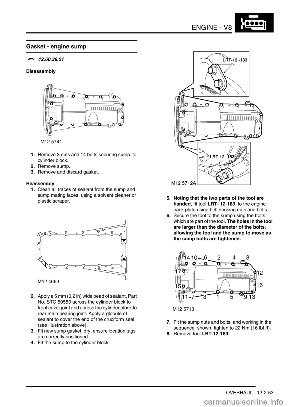
1.Clean all traces of sealant from the sump and
sump mating faces, using a solvent cleaner or
plastic scraper.
2.Apply a 5 mm (0.2 in) wide bead of sealant, Part
No. STC 50550 across the cylinder block to
front cover joint and across the cylinder block to
rear main bearing joint. Apply a globule of
sealant to cover the end of the cruciform seal,
(see illustration above).
3.Fit new sump gasket, dry, ensure location tags
are correctly positioned.
4.Fit the sump to the cylinder block.5. Noting that the two parts of the tool are
handed, fit tool LRT- 12-183 to the engine
back plate using bell housing nuts and bolts.
6.Secure the tool to the sump using the bolts
which are part of the tool. The holes in the tool
are larger than the diameter of the bolts,
allowing the tool and the sump to move as
the sump bolts are tightened.
7.Fit the sump nuts and bolts, and working in the
sequence shown, tighten to 22 Nm (16 lbf.ft).
8.Remove tool LRT-12-183.
M12 5741
M12 5713
14106248
12
16
17
15
117315913
Page 297 of 1672
ENGINE - V8
12-2-54 OVERHAUL
Strainer - oil pick-up
$% 12.60.20.01
Disassembly
1.Remove sump gasket.
+ ENGINE - V8, OVERHAUL, Gasket -
engine sump.
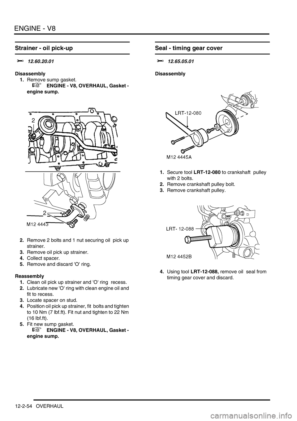
2.Remove 2 bolts and 1 nut securing oil pick up
strainer.
3.Remove oil pick up strainer.
4.Collect spacer.
5.Remove and discard 'O' ring.
Reassembly
1.Clean oil pick up strainer and 'O' ring recess.
2.Lubricate new 'O' ring with clean engine oil and
fit to recess.
3.Locate spacer on stud.
4.Position oil pick up strainer, fit bolts and tighten
to 10 Nm (7 lbf.ft). Fit nut and tighten to 22 Nm
(16 lbf.ft).
5.Fit new sump gasket.
+ ENGINE - V8, OVERHAUL, Gasket -
engine sump.
Seal - timing gear cover
$% 12.65.05.01
Disassembly
1.Secure tool LRT-12-080 to crankshaft pulley
with 2 bolts.
2.Remove crankshaft pulley bolt.
3.Remove crankshaft pulley.
4.Using tool LRT-12-088, remove oil seal from
timing gear cover and discard.
Page 298 of 1672
ENGINE - V8
OVERHAUL 12-2-55
Reassembly
1.Clean seal register in timing gear cover and
crankshaft pulley.
2.Apply Retinax LX grease to inner recess of new
oil seal until recess is half filled with grease.Do
not allow grease to coat any other part of
seal. Do not apply oil to seal.
3.Apply smear of Retinax LX grease to seal
running surface on crankshaft.
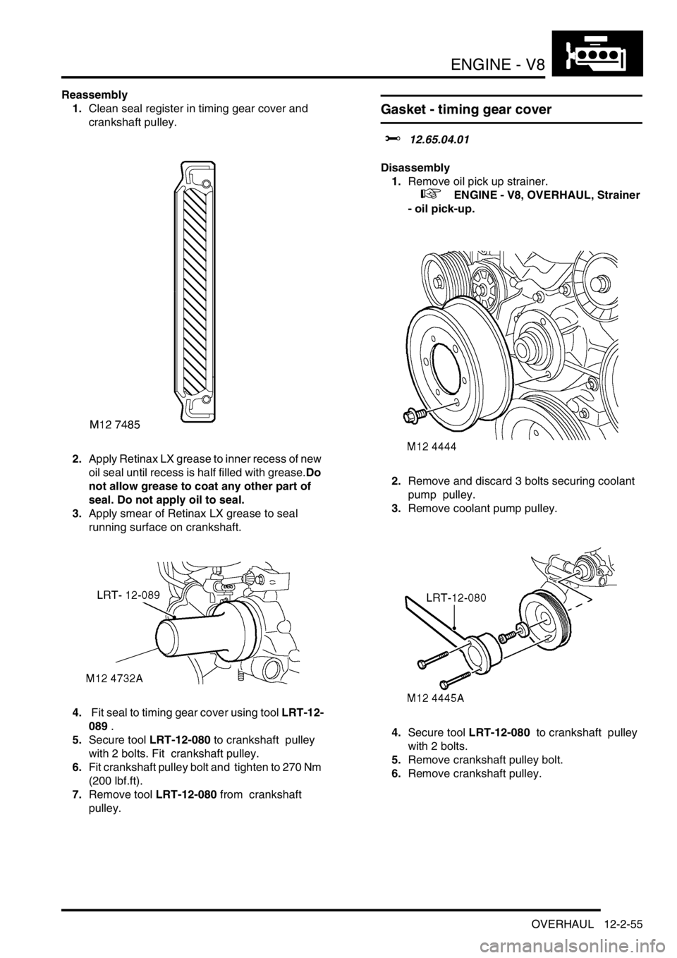
4. Fit seal to timing gear cover using tool LRT-12-
089 .
5.Secure tool LRT-12-080 to crankshaft pulley
with 2 bolts. Fit crankshaft pulley.
6.Fit crankshaft pulley bolt and tighten to 270 Nm
(200 lbf.ft).
7.Remove tool LRT-12-080 from crankshaft
pulley.
Gasket - timing gear cover
$% 12.65.04.01
Disassembly
1.Remove oil pick up strainer.
+ ENGINE - V8, OVERHAUL, Strainer
- oil pick-up.
2.Remove and discard 3 bolts securing coolant
pump pulley.
3.Remove coolant pump pulley.
4.Secure tool LRT-12-080 to crankshaft pulley
with 2 bolts.
5.Remove crankshaft pulley bolt.
6.Remove crankshaft pulley.
Page 299 of 1672
ENGINE - V8
12-2-56 OVERHAUL
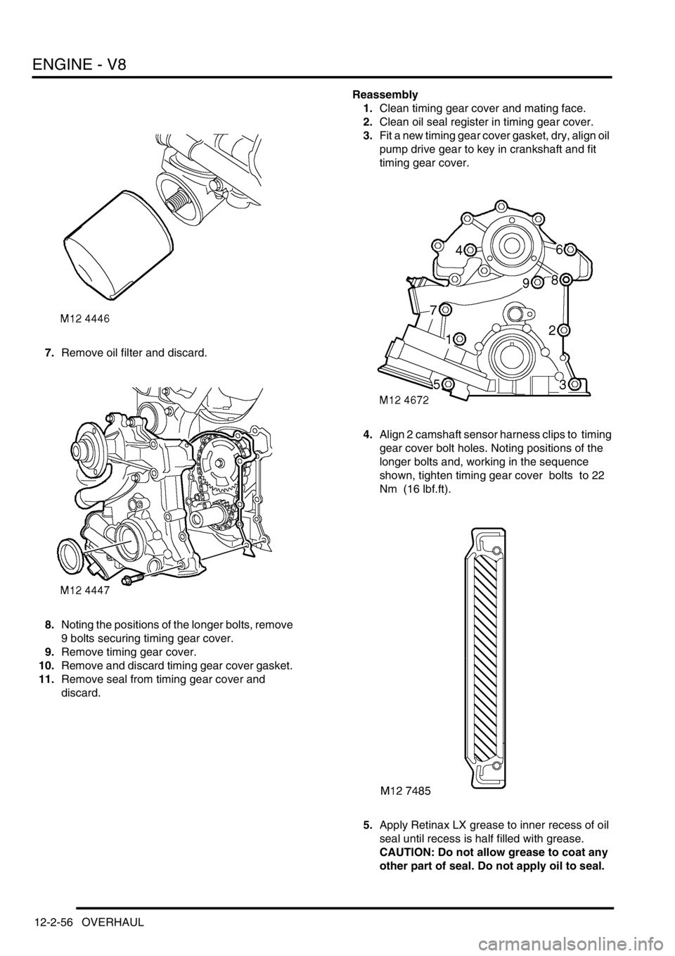
7.Remove oil filter and discard.
8.Noting the positions of the longer bolts, remove
9 bolts securing timing gear cover.
9.Remove timing gear cover.
10.Remove and discard timing gear cover gasket.
11.Remove seal from timing gear cover and
discard. Reassembly
1.Clean timing gear cover and mating face.
2.Clean oil seal register in timing gear cover.
3.Fit a new timing gear cover gasket, dry, align oil
pump drive gear to key in crankshaft and fit
timing gear cover.
4.Align 2 camshaft sensor harness clips to timing
gear cover bolt holes. Noting positions of the
longer bolts and, working in the sequence
shown, tighten timing gear cover bolts to 22
Nm (16 lbf.ft).
5.Apply Retinax LX grease to inner recess of oil
seal until recess is half filled with grease.
CAUTION: Do not allow grease to coat any
other part of seal. Do not apply oil to seal.
Page 302 of 1672
ENGINE - V8
OVERHAUL 12-2-59
Rocker shaft - overhaul
$% 12.29.49
If both rocker shafts are to be removed, identify
each assembly to ensure refitment to original
cylinder head.
Disassembly
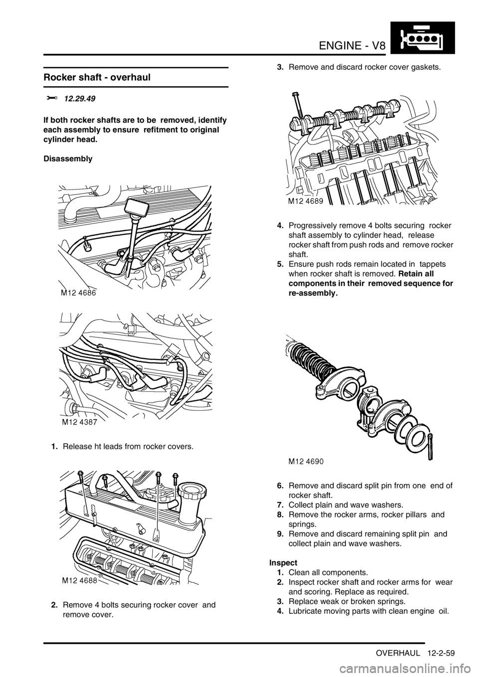
1.Release ht leads from rocker covers.
2.Remove 4 bolts securing rocker cover and
remove cover. 3.Remove and discard rocker cover gaskets.
4.Progressively remove 4 bolts securing rocker
shaft assembly to cylinder head, release
rocker shaft from push rods and remove rocker
shaft.
5.Ensure push rods remain located in tappets
when rocker shaft is removed. Retain all
components in their removed sequence for
re-assembly.
6.Remove and discard split pin from one end of
rocker shaft.
7.Collect plain and wave washers.
8.Remove the rocker arms, rocker pillars and
springs.
9.Remove and discard remaining split pin and
collect plain and wave washers.
Inspect
1.Clean all components.
2.Inspect rocker shaft and rocker arms for wear
and scoring. Replace as required.
3.Replace weak or broken springs.
4.Lubricate moving parts with clean engine oil.
Page 303 of 1672
ENGINE - V8
12-2-60 OVERHAUL
Reassembly
1.Reassemble rocker shafts, ensuring that
components are returned to their original
positions, secure plain washers with new split
pins.
2.Ensure shaft identification groove is positioned
at one o'clock, with push rod locations of rocker
arms to the right. Oil feed restriction will
result if rocker shafts are incorrectly
assembled.
3.Position rocker shaft assembly to cylinder
head ensuring push rods are engaged in
rocker arms.
4.Fit rocker shaft bolts and progressively tighten
to 40 Nm (30 lbf.ft).
5.Clean mating faces of rocker covers and
cylinder heads.
6.Fit new rocker cover gaskets, dry, position
rocker cover, fit bolts and working in diagonal
sequence, tighten to:
lStage 1 - 3 Nm (2.5 lbf.ft)
lStage 2 - 8 Nm (6 lbf.ft)
7.Ensure that gasket is correctly positioned
around periphery of rocker cover.
8.Secure ht leads to rocker cover.
Gasket - cylinder head
$% 12.29.02.01
Disassembly
1.Remove inlet manifold gasket.
+ ENGINE - V8, OVERHAUL, Gasket -
inlet manifold.
2. RH cylinder head: Remove auxiliary drive belt
tensioner.
3. RH cylinder head: Remove bolts securing
alternator mounting bracket and remove
bracket.
4.Noting their fitted order, disconnect ht leads
from spark plugs.
5.Progressively remove 4 bolts securing the
rocker shaft and remove rocker shaft.
6.Remove push rods and store in their fitted
order.
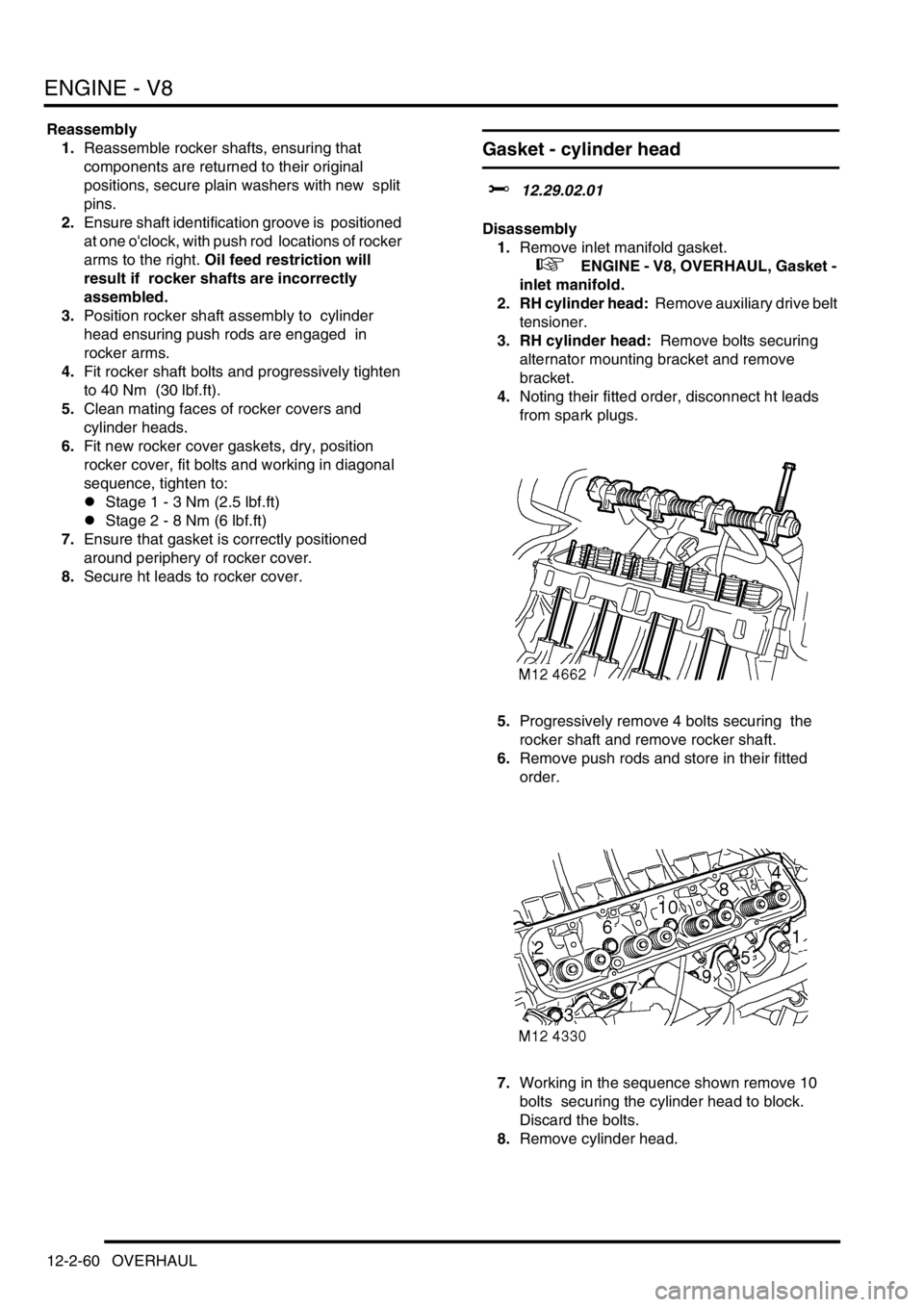
7.Working in the sequence shown remove 10
bolts securing the cylinder head to block.
Discard the bolts.
8.Remove cylinder head.
Page 308 of 1672
ENGINE - V8
OVERHAUL 12-2-65
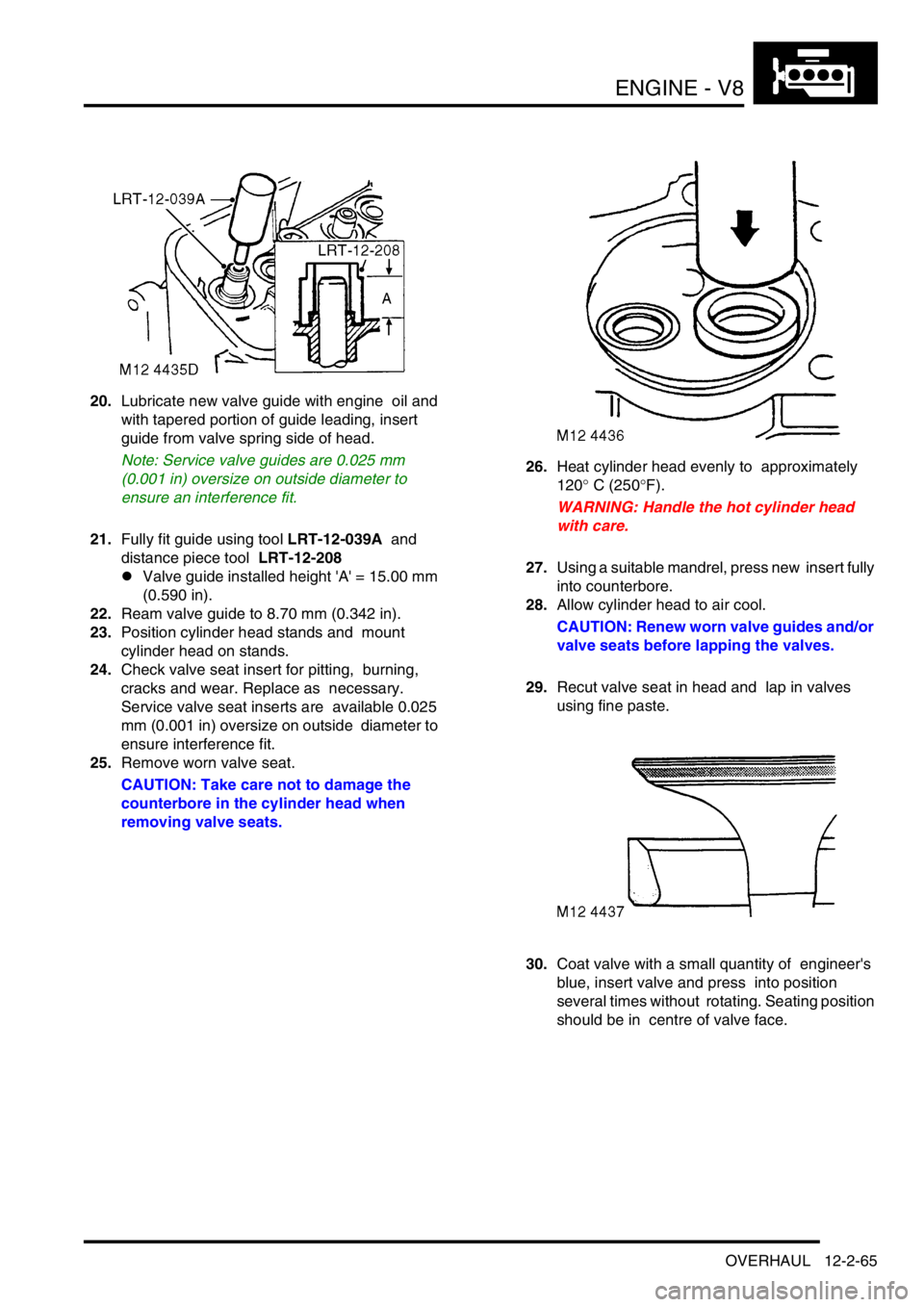
20.Lubricate new valve guide with engine oil and
with tapered portion of guide leading, insert
guide from valve spring side of head.
Note: Service valve guides are 0.025 mm
(0.001 in) oversize on outside diameter to
ensure an interference fit.
21.Fully fit guide using tool LRT-12-039A and
distance piece tool LRT-12-208
lValve guide installed height 'A' = 15.00 mm
(0.590 in).
22.Ream valve guide to 8.70 mm (0.342 in).
23.Position cylinder head stands and mount
cylinder head on stands.
24.Check valve seat insert for pitting, burning,
cracks and wear. Replace as necessary.
Service valve seat inserts are available 0.025
mm (0.001 in) oversize on outside diameter to
ensure interference fit.
25.Remove worn valve seat.
CAUTION: Take care not to damage the
counterbore in the cylinder head when
removing valve seats.26.Heat cylinder head evenly to approximately
120
° C (250°F).
WARNING: Handle the hot cylinder head
with care.
27.Using a suitable mandrel, press new insert fully
into counterbore.
28.Allow cylinder head to air cool.
CAUTION: Renew worn valve guides and/or
valve seats before lapping the valves.
29.Recut valve seat in head and lap in valves
using fine paste.
30.Coat valve with a small quantity of engineer's
blue, insert valve and press into position
several times without rotating. Seating position
should be in centre of valve face.
Page 310 of 1672
ENGINE - V8
OVERHAUL 12-2-67
Piston assemblies
$% 12.17.02.01
Disassembly
1.Remove cylinder head.
+ ENGINE - V8, OVERHAUL, Gasket -
cylinder head.
2.Remove oil pick-up strainer
+ ENGINE - V8, OVERHAUL, Strainer
- oil pick-up.
3.Suitably identify each connecting rod and
piston assembly to its respective cylinder bore.
4.Remove 2 bolts securing each connecting rod
bearing cap.
5.Remove connecting rod bearing cap and
collect connecting rod bearings.
6.Remove ridge of carbon from top of cylinder
bores.
7.Carefully push each piston assembly from the
top of the cylinder.
CAUTION: Ensure that connecting rods do
not contact cylinder bores.
8.Refit bearing cap onto connecting rod, lightly
tighten dowel bolts.
9.Suitably identify each piston to its respective
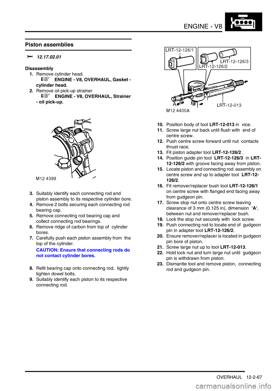
connecting rod.10.Position body of tool LRT-12-013 in vice.
11.Screw large nut back until flush with end of
centre screw.
12.Push centre screw forward until nut contacts
thrust race.
13.Fit piston adapter tool LRT-12-126/2 .
14.Position guide pin tool LRT-12-126/3 in LRT-
12-126/2 with groove facing away from piston.
15.Locate piston and connecting rod assembly on
centre screw and up to adapter tool LRT-12-
126/2.
16.Fit remover/replacer bush tool LRT-12-126/1
on centre screw with flanged end facing away
from gudgeon pin.
17.Screw stop nut onto centre screw leaving
clearance of 3 mm (0.125 in), dimension 'A',
between nut and remover/replacer bush.
18.Lock the stop nut securely with lock screw.
19.Push connecting rod to locate end of gudgeon
pin in adapter tool LRT-12-126/2.
20.Ensure remover/replacer is located in gudgeon
pin bore of piston.
21.Screw large nut up to tool LRT-12-013.
22.Hold lock nut and turn large nut until gudgeon
pin is withdrawn from piston.
23.Dismantle tool and remove piston, connecting
rod and gudgeon pin.
Page 312 of 1672
ENGINE - V8
OVERHAUL 12-2-69
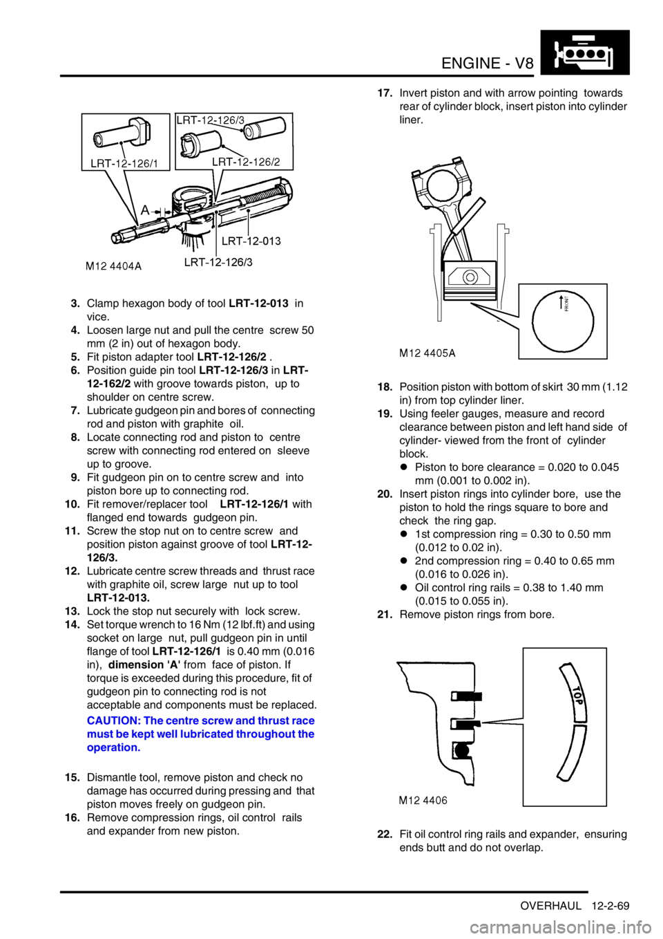
3.Clamp hexagon body of tool LRT-12-013 in
vice.
4.Loosen large nut and pull the centre screw 50
mm (2 in) out of hexagon body.
5.Fit piston adapter tool LRT-12-126/2 .
6.Position guide pin tool LRT-12-126/3 in LRT-
12-162/2 with groove towards piston, up to
shoulder on centre screw.
7.Lubricate gudgeon pin and bores of connecting
rod and piston with graphite oil.
8.Locate connecting rod and piston to centre
screw with connecting rod entered on sleeve
up to groove.
9.Fit gudgeon pin on to centre screw and into
piston bore up to connecting rod.
10.Fit remover/replacer tool LRT-12-126/1 with
flanged end towards gudgeon pin.
11.Screw the stop nut on to centre screw and
position piston against groove of tool LRT-12-
126/3.
12.Lubricate centre screw threads and thrust race
with graphite oil, screw large nut up to tool
LRT-12-013.
13.Lock the stop nut securely with lock screw.
14.Set torque wrench to 16 Nm (12 lbf.ft) and using
socket on large nut, pull gudgeon pin in until
flange of tool LRT-12-126/1 is 0.40 mm (0.016
in), dimension 'A' from face of piston. If
torque is exceeded during this procedure, fit of
gudgeon pin to connecting rod is not
acceptable and components must be replaced.
CAUTION: The centre screw and thrust race
must be kept well lubricated throughout the
operation.
15.Dismantle tool, remove piston and check no
damage has occurred during pressing and that
piston moves freely on gudgeon pin.
16.Remove compression rings, oil control rails
and expander from new piston. 17.Invert piston and with arrow pointing towards
rear of cylinder block, insert piston into cylinder
liner.
18.Position piston with bottom of skirt 30 mm (1.12
in) from top cylinder liner.
19.Using feeler gauges, measure and record
clearance between piston and left hand side of
cylinder- viewed from the front of cylinder
block.
lPiston to bore clearance = 0.020 to 0.045
mm (0.001 to 0.002 in).
20.Insert piston rings into cylinder bore, use the
piston to hold the rings square to bore and
check the ring gap.
l1st compression ring = 0.30 to 0.50 mm
(0.012 to 0.02 in).
l2nd compression ring = 0.40 to 0.65 mm
(0.016 to 0.026 in).
lOil control ring rails = 0.38 to 1.40 mm
(0.015 to 0.055 in).
21.Remove piston rings from bore.
22.Fit oil control ring rails and expander, ensuring
ends butt and do not overlap.
Page 314 of 1672
ENGINE - V8
OVERHAUL 12-2-71
Bearings - connecting rods
$% 12.17.16.01
Disassembly
1.Remove oil pick up strainer.
+ ENGINE - V8, OVERHAUL, Strainer
- oil pick-up.
2.Suitably mark cylinder reference number on
each connecting rod bearing cap.
3.Remove 2 bolts securing each connecting rod
bearing cap, remove caps and recover
connecting rod bearings.
CAUTION: Keep bearing caps, bearings and
bolts in their fitted order.
4.Push each connecting rod up cylinder bore
until connecting rods are clear of crankshaft
journals.
CAUTION: Ensure that connecting rods do
not contact cylinder bores.
5.Remove bearing shells from each connecting
rod.
Inspect
1.Clean crankshaft journals and bearing
locations in connecting rods.
2.Inspect connecting rod bearings for wear and
renew if necessary. Connecting rod bearings
are available in two oversizes.
lConnecting rod bearing 1st oversize = 0.254
mm (0.01 in).
lConnecting rod bearing 2nd oversize =
0.508 mm (0.02 in).3.Check crankshaft big-end journals for wear and
scoring. Measure for ovality; taking 3
measurements at 120
° intervals at each end
and at centre of journals.
lStandard journal = 55.500 to 55.513 mm
(2.20 to 2.22 in).
l1st undersize journal - 0.254 mm (0.01 in) =
55.246 to 55.259 mm (2.17 to 2.18 in).
l2nd undersize journal - 0.508 mm (0.02 in)
= 54.992 to 55.005 mm (2.16 to 2.165 in).
lJournal - max. ovality = 0.040 mm (0.002 in)
Reassembly
1.Clean connecting rod caps.
2.Lubricate connecting rod journals and bearing
shells with clean engine oil.
3.Fit bearing shells to connecting rods and caps.
4.Rotate crankshaft until connecting rod journals
are correctly positioned.
5.Taking care not to displace bearing shells, pull
connecting rods on to crankshaft journals.
6.Check that bearing shells are correctly located
in connecting rod bearing caps.
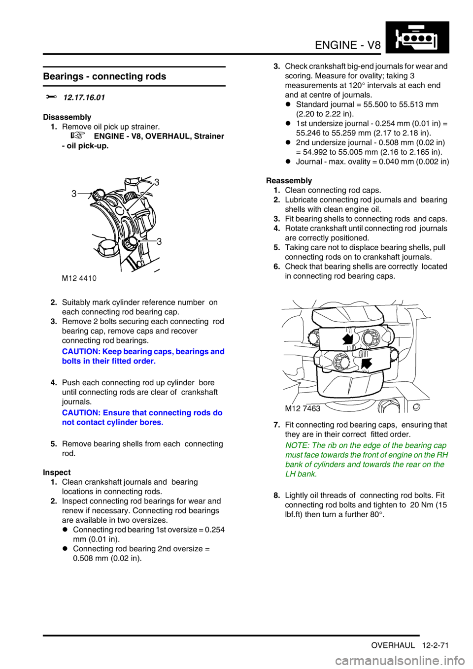
7.Fit connecting rod bearing caps, ensuring that
they are in their correct fitted order.
NOTE: The rib on the edge of the bearing cap
must face towards the front of engine on the RH
bank of cylinders and towards the rear on the
LH bank.
8.Lightly oil threads of connecting rod bolts. Fit
connecting rod bolts and tighten to 20 Nm (15
lbf.ft) then turn a further 80
°.