tow LAND ROVER FREELANDER 2001 User Guide
[x] Cancel search | Manufacturer: LAND ROVER, Model Year: 2001, Model line: FREELANDER, Model: LAND ROVER FREELANDER 2001Pages: 1007, PDF Size: 23.47 MB
Page 98 of 1007
GENERAL DATA
04-35
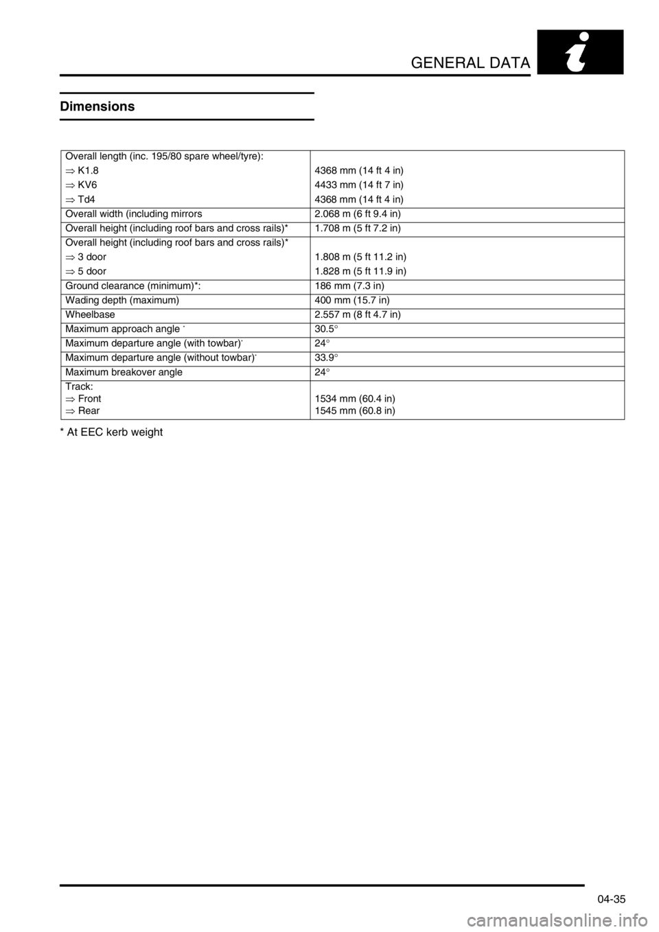
Dimensions
* At EEC kerb weight
Overall length (inc. 195/80 spare wheel/tyre):
⇒ K1.8 4368 mm (14 ft 4 in)
⇒ KV6 4433 mm (14 ft 7 in)
⇒ Td4 4368 mm (14 ft 4 in)
Overall width (including mirrors 2.068 m (6 ft 9.4 in)
Overall height (including roof bars and cross rails)* 1.708 m (5 ft 7.2 in)
Overall height (including roof bars and cross rails)*
⇒ 3 door 1.808 m (5 ft 11.2 in)
⇒ 5 door 1.828 m (5 ft 11.9 in)
Ground clearance (minimum)*: 186 mm (7.3 in)
Wading depth (maximum) 400 mm (15.7 in)
Wheelbase 2.557 m (8 ft 4.7 in)
Maximum approach angle
*30.5°
Maximum departure angle (with towbar)
*24°
Maximum departure angle (without towbar)
*33.9°
Maximum breakover angle 24°
Track:
⇒ Front
⇒ Rear1534 mm (60.4 in)
1545 mm (60.8 in)
Page 99 of 1007
GENERAL DATA
04-36
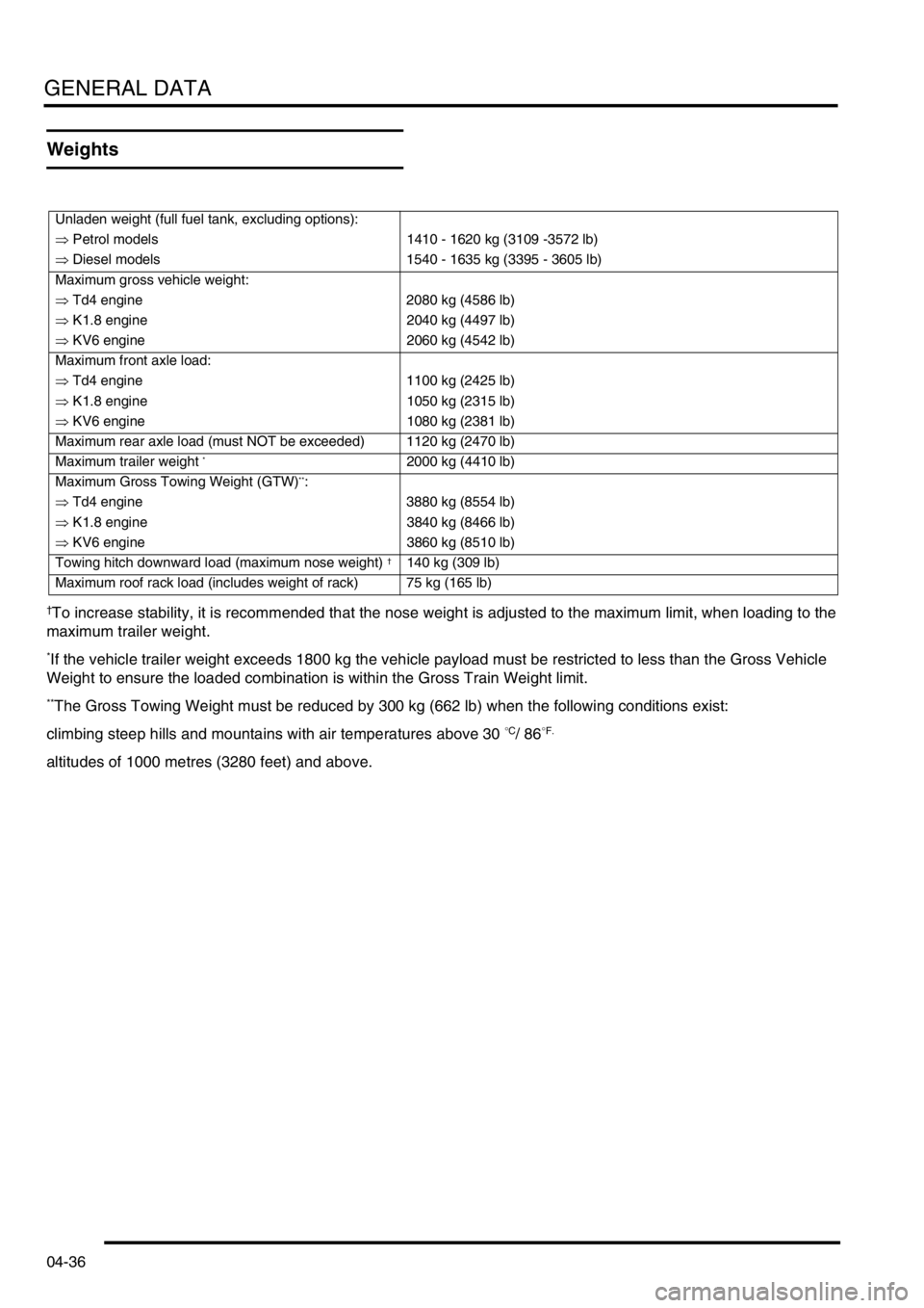
Weights
†To increase stability, it is recommended that the nose weight is adjusted to the maximum limit, when loading to the
maximum trailer weight.
*If the vehicle trailer weight exceeds 1800 kg the vehicle payload must be restricted to less than the Gross Vehicle
Weight to ensure the loaded combination is within the Gross Train Weight limit.
**The Gross Towing Weight must be reduced by 300 kg (662 lb) when the following conditions exist:
climbing steep hills and mountains with air temperatures above 30
°C/ 86°F.
altitudes of 1000 metres (3280 feet) and above.
Unladen weight (full fuel tank, excluding options):
⇒ Petrol models 1410 - 1620 kg (3109 -3572 lb)
⇒ Diesel models 1540 - 1635 kg (3395 - 3605 lb)
Maximum gross vehicle weight:
⇒ Td4 engine 2080 kg (4586 lb)
⇒ K1.8 engine 2040 kg (4497 lb)
⇒ KV6 engine 2060 kg (4542 lb)
Maximum front axle load:
⇒ Td4 engine 1100 kg (2425 lb)
⇒ K1.8 engine 1050 kg (2315 lb)
⇒ KV6 engine 1080 kg (2381 lb)
Maximum rear axle load (must NOT be exceeded) 1120 kg (2470 lb)
Maximum trailer weight
*2000 kg (4410 lb)
Maximum Gross Towing Weight (GTW)
**:
⇒ Td4 engine 3880 kg (8554 lb)
⇒ K1.8 engine 3840 kg (8466 lb)
⇒ KV6 engine 3860 kg (8510 lb)
Towing hitch downward load (maximum nose weight)
†140 kg (309 lb)
Maximum roof rack load (includes weight of rack) 75 kg (165 lb)
Page 140 of 1007
LIFTING AND TOWING
08-1
LIFTING AND TOWING
Jacking
The following instructions must be carried out before
raising the vehicle off the ground:
lUse a solid level surface.
lApply parking brake.
lSelect 1st. gear in main gearbox and ensure
HDC is not selected.
CAUTION: To avoid damage to under body
components of the vehicle, adhere to the
following jacking procedures:
DO NOT POSITION JACKS OR AXLE STANDS
UNDER THE FOLLOWING COMPONENTS:
lBumpers
lBrake or Fuel lines
lExhaust pipe
lSuspension components
lSteering rack and linkages
lFuel tank
lEngine sump
lGearbox
lIRD unit
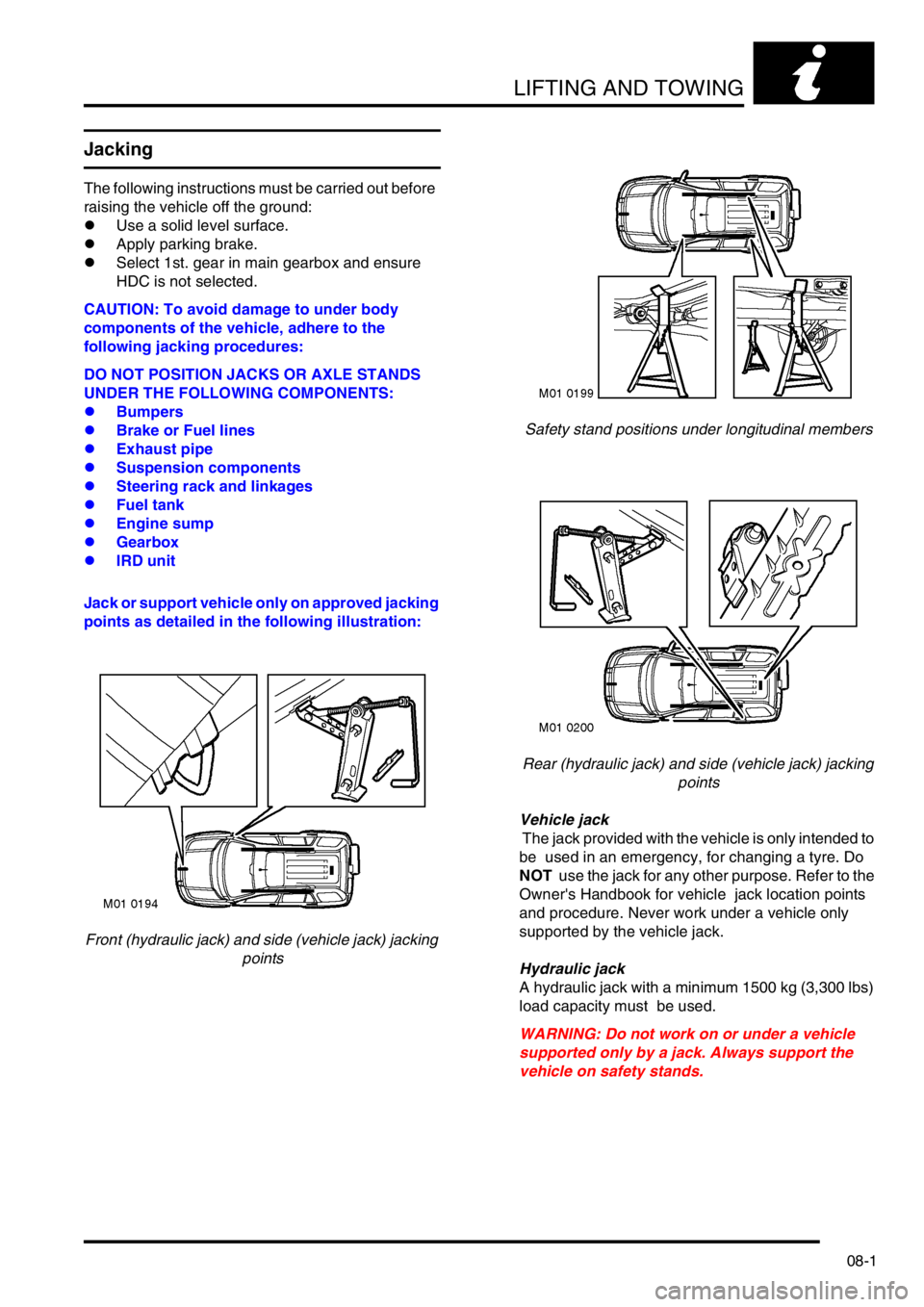
Jack or support vehicle only on approved jacking
points as detailed in the following illustration:
Front (hydraulic jack) and side (vehicle jack) jacking
pointsSafety stand positions under longitudinal members
Rear (hydraulic jack) and side (vehicle jack) jacking
points
Vehicle jack
The jack provided with the vehicle is only intended to
be used in an emergency, for changing a tyre. Do
NOT use the jack for any other purpose. Refer to the
Owner's Handbook for vehicle jack location points
and procedure. Never work under a vehicle only
supported by the vehicle jack.
Hydraulic jack
A hydraulic jack with a minimum 1500 kg (3,300 lbs)
load capacity must be used.
WARNING: Do not work on or under a vehicle
supported only by a jack. Always support the
vehicle on safety stands.
Page 141 of 1007
LIFTING AND TOWING
08-2
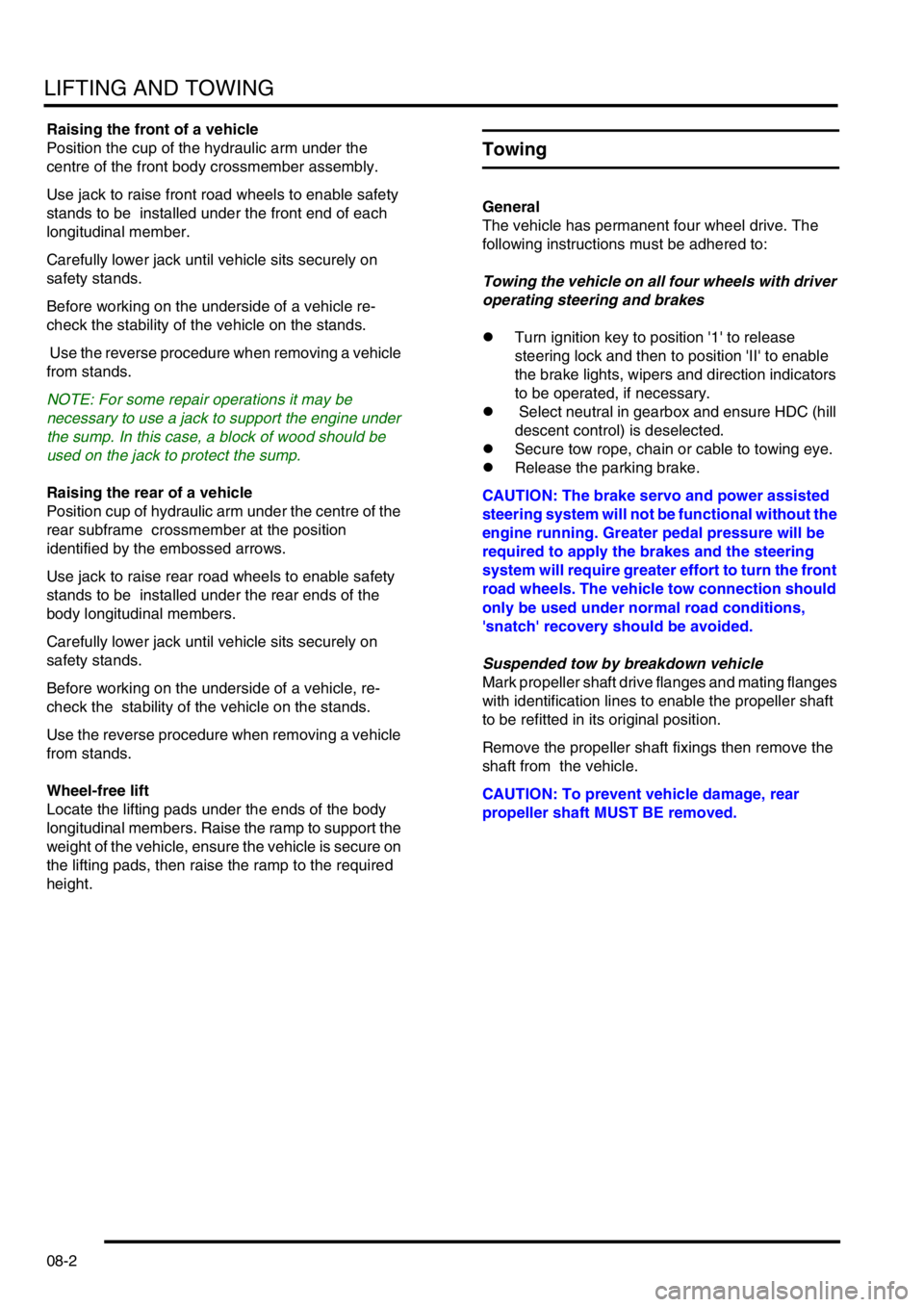
Raising the front of a vehicle
Position the cup of the hydraulic arm under the
centre of the front body crossmember assembly.
Use jack to raise front road wheels to enable safety
stands to be installed under the front end of each
longitudinal member.
Carefully lower jack until vehicle sits securely on
safety stands.
Before working on the underside of a vehicle re-
check the stability of the vehicle on the stands.
Use the reverse procedure when removing a vehicle
from stands.
NOTE: For some repair operations it may be
necessary to use a jack to support the engine under
the sump. In this case, a block of wood should be
used on the jack to protect the sump.
Raising the rear of a vehicle
Position cup of hydraulic arm under the centre of the
rear subframe crossmember at the position
identified by the embossed arrows.
Use jack to raise rear road wheels to enable safety
stands to be installed under the rear ends of the
body longitudinal members.
Carefully lower jack until vehicle sits securely on
safety stands.
Before working on the underside of a vehicle, re-
check the stability of the vehicle on the stands.
Use the reverse procedure when removing a vehicle
from stands.
Wheel-free lift
Locate the lifting pads under the ends of the body
longitudinal members. Raise the ramp to support the
weight of the vehicle, ensure the vehicle is secure on
the lifting pads, then raise the ramp to the required
height.
Towing
General
The vehicle has permanent four wheel drive. The
following instructions must be adhered to:
Towing the vehicle on all four wheels with driver
operating steering and brakes
lTurn ignition key to position '1' to release
steering lock and then to position 'II' to enable
the brake lights, wipers and direction indicators
to be operated, if necessary.
l Select neutral in gearbox and ensure HDC (hill
descent control) is deselected.
lSecure tow rope, chain or cable to towing eye.
lRelease the parking brake.
CAUTION: The brake servo and power assisted
steering system will not be functional without the
engine running. Greater pedal pressure will be
required to apply the brakes and the steering
system will require greater effort to turn the front
road wheels. The vehicle tow connection should
only be used under normal road conditions,
'snatch' recovery should be avoided.
Suspended tow by breakdown vehicle
Mark propeller shaft drive flanges and mating flanges
with identification lines to enable the propeller shaft
to be refitted in its original position.
Remove the propeller shaft fixings then remove the
shaft from the vehicle.
CAUTION: To prevent vehicle damage, rear
propeller shaft MUST BE removed.
Page 142 of 1007
LIFTING AND TOWING
08-3
If the front of the vehicle is to be trailed, turn ignition
key to position 'I' to release steering lock.
WARNING: Do not turn the starter switch to
position '0' or remove the ignition key while the
vehicle is being towed.
CAUTION: If it is considered unsafe to turn the
starter switch to position '1' due to accident
damage or an electrical fault; disconnect the
battery before turning the ignition switch.
CAUTION: The steering wheel and/or linkage
must be secured in a straight ahead position. DO
NOT use the steering lock mechanism for this
purpose.
CAUTION: Under no circumstances should the
vehicle be towed or recovered by means of
lashing to the rear subframe. Serious damage to
the subframe and body could result.
CAUTION: Only use the rear towing eye for
towing another vehicle.
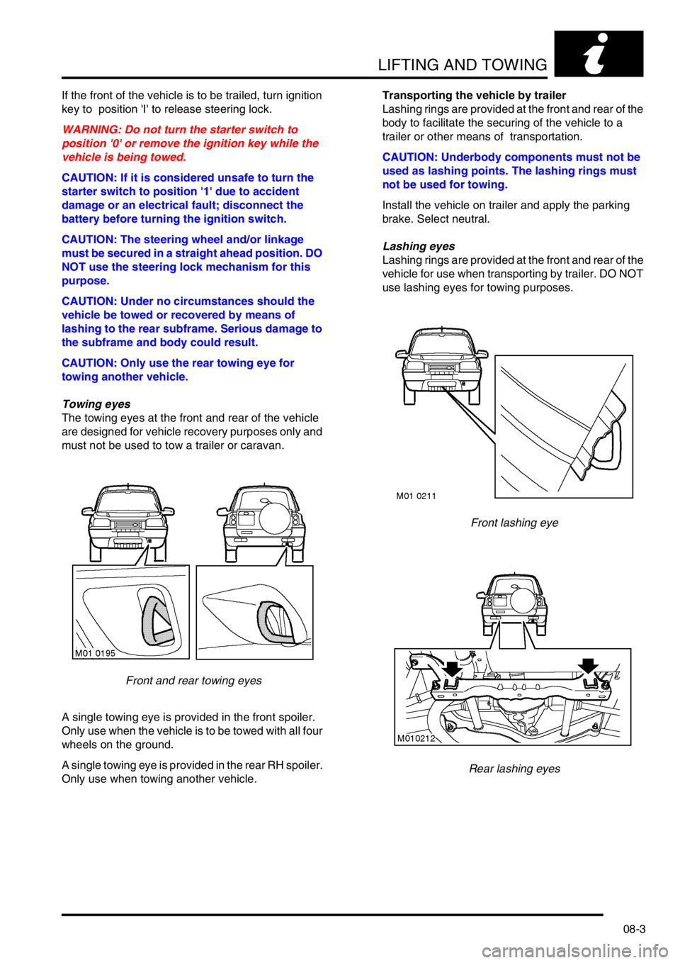
Towing eyes
The towing eyes at the front and rear of the vehicle
are designed for vehicle recovery purposes only and
must not be used to tow a trailer or caravan.
Front and rear towing eyes
A single towing eye is provided in the front spoiler.
Only use when the vehicle is to be towed with all four
wheels on the ground.
A single towing eye is provided in the rear RH spoiler.
Only use when towing another vehicle.Transporting the vehicle by trailer
Lashing rings are provided at the front and rear of the
body to facilitate the securing of the vehicle to a
trailer or other means of transportation.
CAUTION: Underbody components must not be
used as lashing points. The lashing rings must
not be used for towing.
Install the vehicle on trailer and apply the parking
brake. Select neutral.
Lashing eyes
Lashing rings are provided at the front and rear of the
vehicle for use when transporting by trailer. DO NOT
use lashing eyes for towing purposes.
Front lashing eye
Rear lashing eyes
Page 143 of 1007
LIFTING AND TOWING
08-4
Emergency starting
WARNING: Battery fluid (electrolyte) contains
sulphuric acid. It may cause severe burns if it
gets on your skin or in your eyes. Wear
protective clothing and a face shield.
If electrolyte gets on your skin or clothes,
immediately rinse it off with water.
If electrolyte gets in your eyes, immediately flush
eyes with water for at least 15 minutes and seek
medical help.
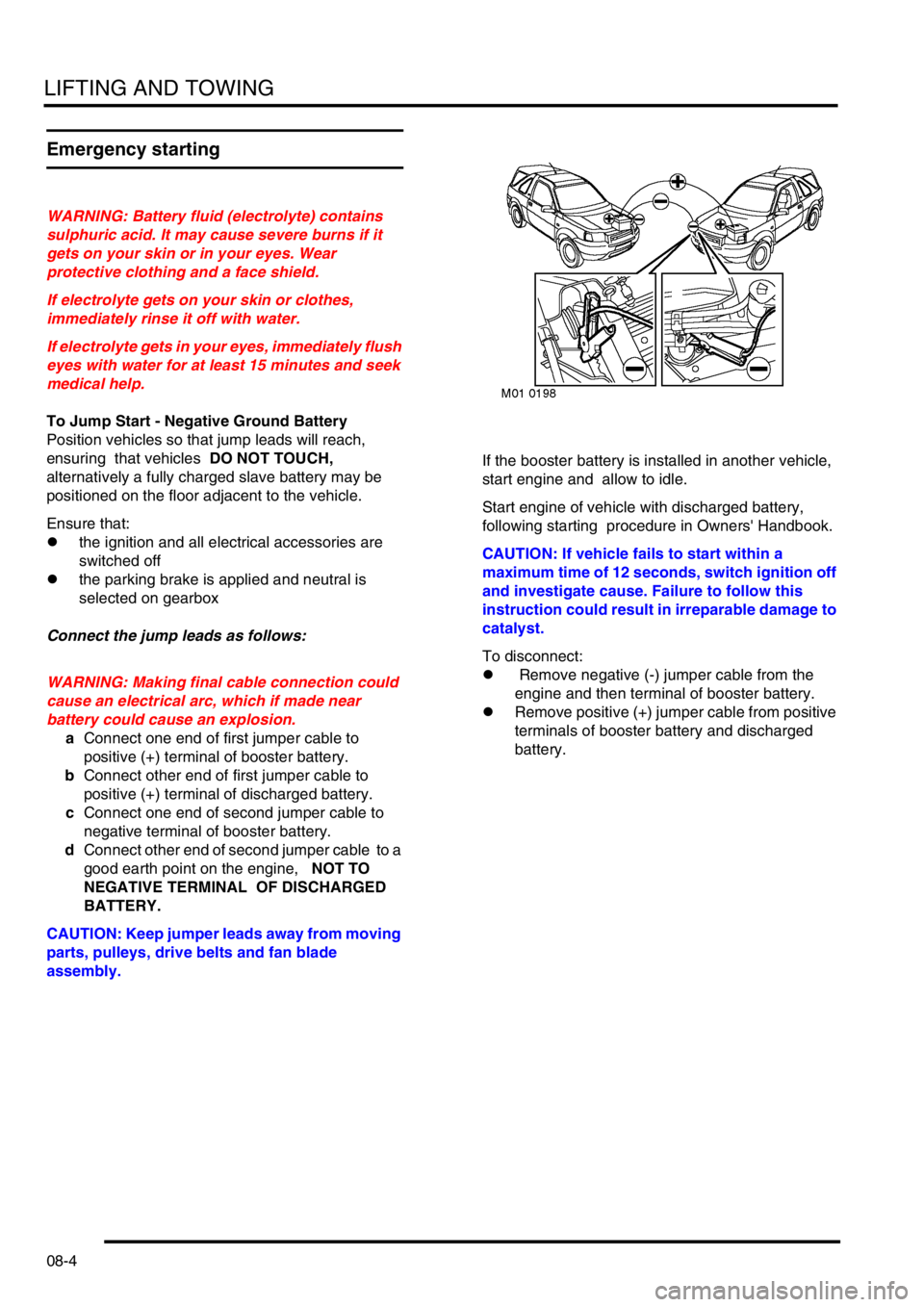
To Jump Start - Negative Ground Battery
Position vehicles so that jump leads will reach,
ensuring that vehicles DO NOT TOUCH,
alternatively a fully charged slave battery may be
positioned on the floor adjacent to the vehicle.
Ensure that:
lthe ignition and all electrical accessories are
switched off
lthe parking brake is applied and neutral is
selected on gearbox
Connect the jump leads as follows:
WARNING: Making final cable connection could
cause an electrical arc, which if made near
battery could cause an explosion.
aConnect one end of first jumper cable to
positive (+) terminal of booster battery.
bConnect other end of first jumper cable to
positive (+) terminal of discharged battery.
cConnect one end of second jumper cable to
negative terminal of booster battery.
dConnect other end of second jumper cable to a
good earth point on the engine, NOT TO
NEGATIVE TERMINAL OF DISCHARGED
BATTERY.
CAUTION: Keep jumper leads away from moving
parts, pulleys, drive belts and fan blade
assembly.If the booster battery is installed in another vehicle,
start engine and allow to idle.
Start engine of vehicle with discharged battery,
following starting procedure in Owners' Handbook.
CAUTION: If vehicle fails to start within a
maximum time of 12 seconds, switch ignition off
and investigate cause. Failure to follow this
instruction could result in irreparable damage to
catalyst.
To disconnect:
l Remove negative (-) jumper cable from the
engine and then terminal of booster battery.
lRemove positive (+) jumper cable from positive
terminals of booster battery and discharged
battery.
Page 174 of 1007
MAINTENANCE
MAINTENANCE 10-27
Suspension
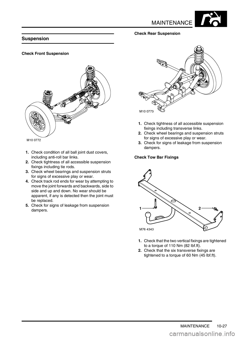
Check Front Suspension
1.Check condition of all ball joint dust covers,
including anti-roll bar links.
2.Check tightness of all accessible suspension
fixings including tie rods.
3.Check wheel bearings and suspension struts
for signs of excessive play or wear.
4.Check track rod ends for wear by attempting to
move the joint forwards and backwards, side to
side and up and down. No wear should be
apparent, if any is detected then the joint must
be replaced.
5.Check for signs of leakage from suspension
dampers.Check Rear Suspension
1.Check tightness of all accessible suspension
fixings including transverse links.
2.Check wheel bearings and suspension struts
for signs of excessive play or wear.
3.Check for signs of leakage from suspension
dampers.
Check Tow Bar Fixings
1.Check that the two vertical fixings are tightened
to a torque of 110 Nm (82 lbf.ft).
2.Check that the six transverse fixings are
tightened to a torque of 60 Nm (45 lbf.ft).
Page 181 of 1007
ENGINE - K SERIES KV6
12-3-4 REPAIRS
Refit
1.Thoroughly clean and lubricate hydraulic
tappets with clean engine oil. Fit hydraulic
tappets to original bores in cylinder head.
2.Ensure that mating faces of camshaft carrier
and cylinder head are clean and dry.
3.Lubricate camshafts and bearing journals with
clean engine oil.
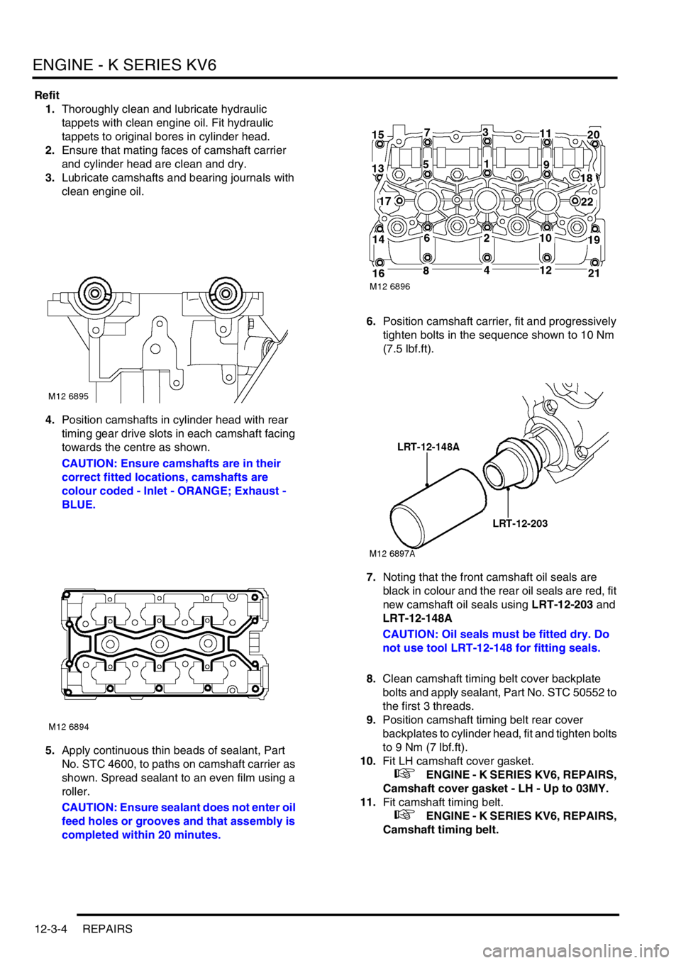
4.Position camshafts in cylinder head with rear
timing gear drive slots in each camshaft facing
towards the centre as shown.
CAUTION: Ensure camshafts are in their
correct fitted locations, camshafts are
colour coded - Inlet - ORANGE; Exhaust -
BLUE.
5.Apply continuous thin beads of sealant, Part
No. STC 4600, to paths on camshaft carrier as
shown. Spread sealant to an even film using a
roller.
CAUTION: Ensure sealant does not enter oil
feed holes or grooves and that assembly is
completed within 20 minutes.6.Position camshaft carrier, fit and progressively
tighten bolts in the sequence shown to 10 Nm
(7.5 lbf.ft).
7.Noting that the front camshaft oil seals are
black in colour and the rear oil seals are red, fit
new camshaft oil seals using LRT-12-203 and
LRT-12-148A
CAUTION: Oil seals must be fitted dry. Do
not use tool LRT-12-148 for fitting seals.
8.Clean camshaft timing belt cover backplate
bolts and apply sealant, Part No. STC 50552 to
the first 3 threads.
9.Position camshaft timing belt rear cover
backplates to cylinder head, fit and tighten bolts
to 9 Nm (7 lbf.ft).
10.Fit LH camshaft cover gasket.
+ ENGINE - K SERIES KV6, REPAIRS,
Camshaft cover gasket - LH - Up to 03MY.
11.Fit camshaft timing belt.
+ ENGINE - K SERIES KV6, REPAIRS,
Camshaft timing belt.
Page 183 of 1007
ENGINE - K SERIES KV6
12-3-6 REPAIRS
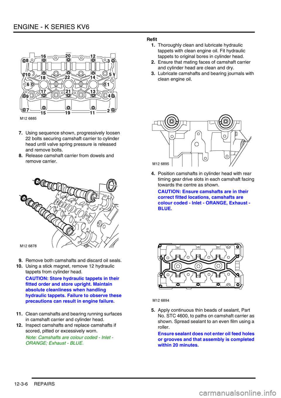
7.Using sequence shown, progressively loosen
22 bolts securing camshaft carrier to cylinder
head until valve spring pressure is released
and remove bolts.
8.Release camshaft carrier from dowels and
remove carrier.
9.Remove both camshafts and discard oil seals.
10.Using a stick magnet, remove 12 hydraulic
tappets from cylinder head.
CAUTION: Store hydraulic tappets in their
fitted order and store upright. Maintain
absolute cleanliness when handling
hydraulic tappets. Failure to observe these
precautions can result in engine failure.
11.Clean camshafts and bearing running surfaces
in camshaft carrier and cylinder head.
12.Inspect camshafts and replace camshafts if
scored, pitted or excessively worn.
Note: Camshafts are colour coded - Inlet -
ORANGE; Exhaust - BLUE.Refit
1.Thoroughly clean and lubricate hydraulic
tappets with clean engine oil. Fit hydraulic
tappets to original bores in cylinder head.
2.Ensure that mating faces of camshaft carrier
and cylinder head are clean and dry.
3.Lubricate camshafts and bearing journals with
clean engine oil.
4.Position camshafts in cylinder head with rear
timing gear drive slots in each camshaft facing
towards the centre as shown.
CAUTION: Ensure camshafts are in their
correct fitted locations, camshafts are
colour coded - Inlet - ORANGE, Exhaust -
BLUE.
5.Apply continuous thin beads of sealant, Part
No. STC 4600, to paths on camshaft carrier as
shown. Spread sealant to an even film using a
roller.
Ensure sealant does not enter oil feed holes
or grooves and that assembly is completed
within 20 minutes.
Page 198 of 1007
ENGINE - K SERIES KV6
REPAIRS 12-3-21
Refit
1.Clean mating surfaces of camshaft cover and
carrier.
2.Clean inside of camshaft cover. If necessary,
wash oil separator elements in solvent and
blow dry.
3.Position new gasket to camshaft carrier with
arrows on gasket pointing towards inlet
manifold.
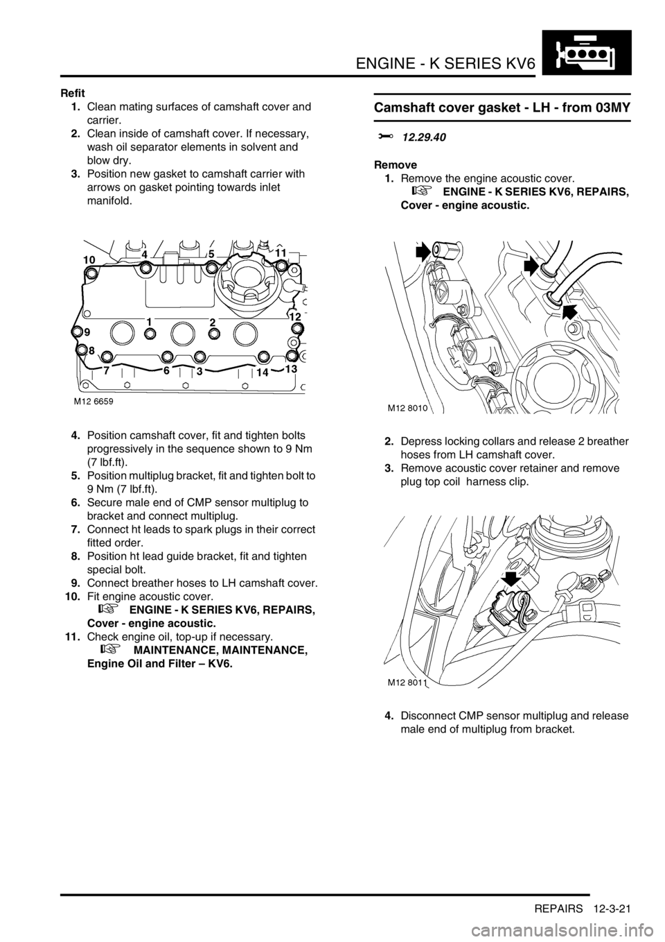
4.Position camshaft cover, fit and tighten bolts
progressively in the sequence shown to 9 Nm
(7 lbf.ft).
5.Position multiplug bracket, fit and tighten bolt to
9 Nm (7 lbf.ft).
6.Secure male end of CMP sensor multiplug to
bracket and connect multiplug.
7.Connect ht leads to spark plugs in their correct
fitted order.
8.Position ht lead guide bracket, fit and tighten
special bolt.
9.Connect breather hoses to LH camshaft cover.
10.Fit engine acoustic cover.
+ ENGINE - K SERIES KV6, REPAIRS,
Cover - engine acoustic.
11.Check engine oil, top-up if necessary.
+ MAINTENANCE, MAINTENANCE,
Engine Oil and Filter – KV6.
Camshaft cover gasket - LH - from 03MY
$% 12.29.40
Remove
1.Remove the engine acoustic cover.
+ ENGINE - K SERIES KV6, REPAIRS,
Cover - engine acoustic.
2.Depress locking collars and release 2 breather
hoses from LH camshaft cover.
3.Remove acoustic cover retainer and remove
plug top coil harness clip.
4.Disconnect CMP sensor multiplug and release
male end of multiplug from bracket.