light LAND ROVER FREELANDER 2001 Owner's Manual
[x] Cancel search | Manufacturer: LAND ROVER, Model Year: 2001, Model line: FREELANDER, Model: LAND ROVER FREELANDER 2001Pages: 1007, PDF Size: 23.47 MB
Page 171 of 1007
MAINTENANCE
10-24 MAINTENANCE
Engine Oil and Filter – KV6
Drain
1.Raise vehicle on ramp.
2.Remove underbelly panel.
+ EXTERIOR FITTINGS, REPAIRS,
Panel - underbelly.
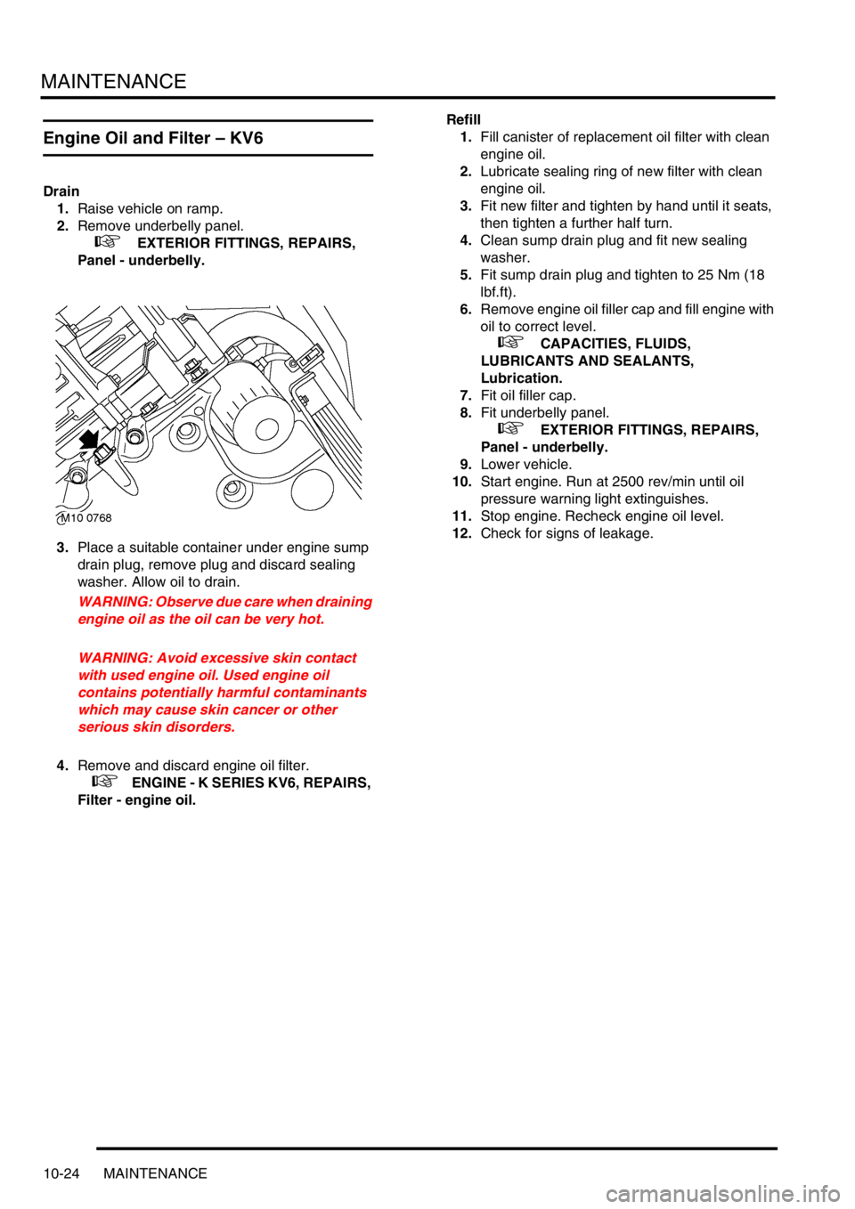
3.Place a suitable container under engine sump
drain plug, remove plug and discard sealing
washer. Allow oil to drain.
WARNING: Observe due care when draining
engine oil as the oil can be very hot.
WARNING: Avoid excessive skin contact
with used engine oil. Used engine oil
contains potentially harmful contaminants
which may cause skin cancer or other
serious skin disorders.
4.Remove and discard engine oil filter.
+ ENGINE - K SERIES KV6, REPAIRS,
Filter - engine oil.Refill
1.Fill canister of replacement oil filter with clean
engine oil.
2.Lubricate sealing ring of new filter with clean
engine oil.
3.Fit new filter and tighten by hand until it seats,
then tighten a further half turn.
4.Clean sump drain plug and fit new sealing
washer.
5.Fit sump drain plug and tighten to 25 Nm (18
lbf.ft).
6.Remove engine oil filler cap and fill engine with
oil to correct level.
+ CAPACITIES, FLUIDS,
LUBRICANTS AND SEALANTS,
Lubrication.
7.Fit oil filler cap.
8.Fit underbelly panel.
+ EXTERIOR FITTINGS, REPAIRS,
Panel - underbelly.
9.Lower vehicle.
10.Start engine. Run at 2500 rev/min until oil
pressure warning light extinguishes.
11.Stop engine. Recheck engine oil level.
12.Check for signs of leakage.
Page 192 of 1007
ENGINE - K SERIES KV6
REPAIRS 12-3-15
Refit
1.Clean cylinder head mating face.
CAUTION: Use suitable gasket removal
spray and a plastic scraper.
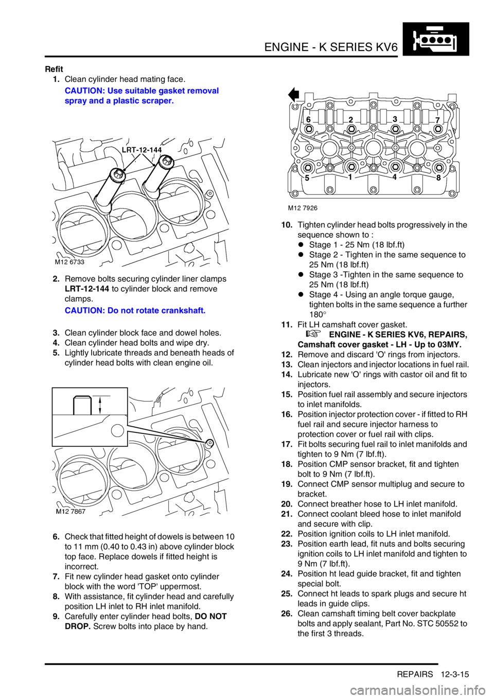
2.Remove bolts securing cylinder liner clamps
LRT-12-144 to cylinder block and remove
clamps.
CAUTION: Do not rotate crankshaft.
3.Clean cylinder block face and dowel holes.
4.Clean cylinder head bolts and wipe dry.
5.Lightly lubricate threads and beneath heads of
cylinder head bolts with clean engine oil.
6.Check that fitted height of dowels is between 10
to 11 mm (0.40 to 0.43 in) above cylinder block
top face. Replace dowels if fitted height is
incorrect.
7.Fit new cylinder head gasket onto cylinder
block with the word 'TOP' uppermost.
8.With assistance, fit cylinder head and carefully
position LH inlet to RH inlet manifold.
9.Carefully enter cylinder head bolts, DO NOT
DROP. Screw bolts into place by hand.10.Tighten cylinder head bolts progressively in the
sequence shown to :
lStage 1 - 25 Nm (18 lbf.ft)
lStage 2 - Tighten in the same sequence to
25 Nm (18 lbf.ft)
lStage 3 -Tighten in the same sequence to
25 Nm (18 lbf.ft)
lStage 4 - Using an angle torque gauge,
tighten bolts in the same sequence a further
180°
11.Fit LH camshaft cover gasket.
+ ENGINE - K SERIES KV6, REPAIRS,
Camshaft cover gasket - LH - Up to 03MY.
12.Remove and discard 'O' rings from injectors.
13.Clean injectors and injector locations in fuel rail.
14.Lubricate new 'O' rings with castor oil and fit to
injectors.
15.Position fuel rail assembly and secure injectors
to inlet manifolds.
16.Position injector protection cover - if fitted to RH
fuel rail and secure injector harness to
protection cover or fuel rail with clips.
17.Fit bolts securing fuel rail to inlet manifolds and
tighten to 9 Nm (7 lbf.ft).
18.Position CMP sensor bracket, fit and tighten
bolt to 9 Nm (7 lbf.ft).
19.Connect CMP sensor multiplug and secure to
bracket.
20.Connect breather hose to LH inlet manifold.
21.Connect coolant bleed hose to inlet manifold
and secure with clip.
22.Position ignition coils to LH inlet manifold.
23.Position earth lead, fit nuts and bolts securing
ignition coils to LH inlet manifold and tighten to
9 Nm (7 lbf.ft).
24.Position ht lead guide bracket, fit and tighten
special bolt.
25.Connect ht leads to spark plugs and secure ht
leads in guide clips.
26.Clean camshaft timing belt cover backplate
bolts and apply sealant, Part No. STC 50552 to
the first 3 threads.
Page 195 of 1007
ENGINE - K SERIES KV6
12-3-18 REPAIRS
13.Release injectors from manifolds and carefully
lay fuel rail and injectors aside.
CAUTION: Always fit plugs to open
connections to prevent contamination.
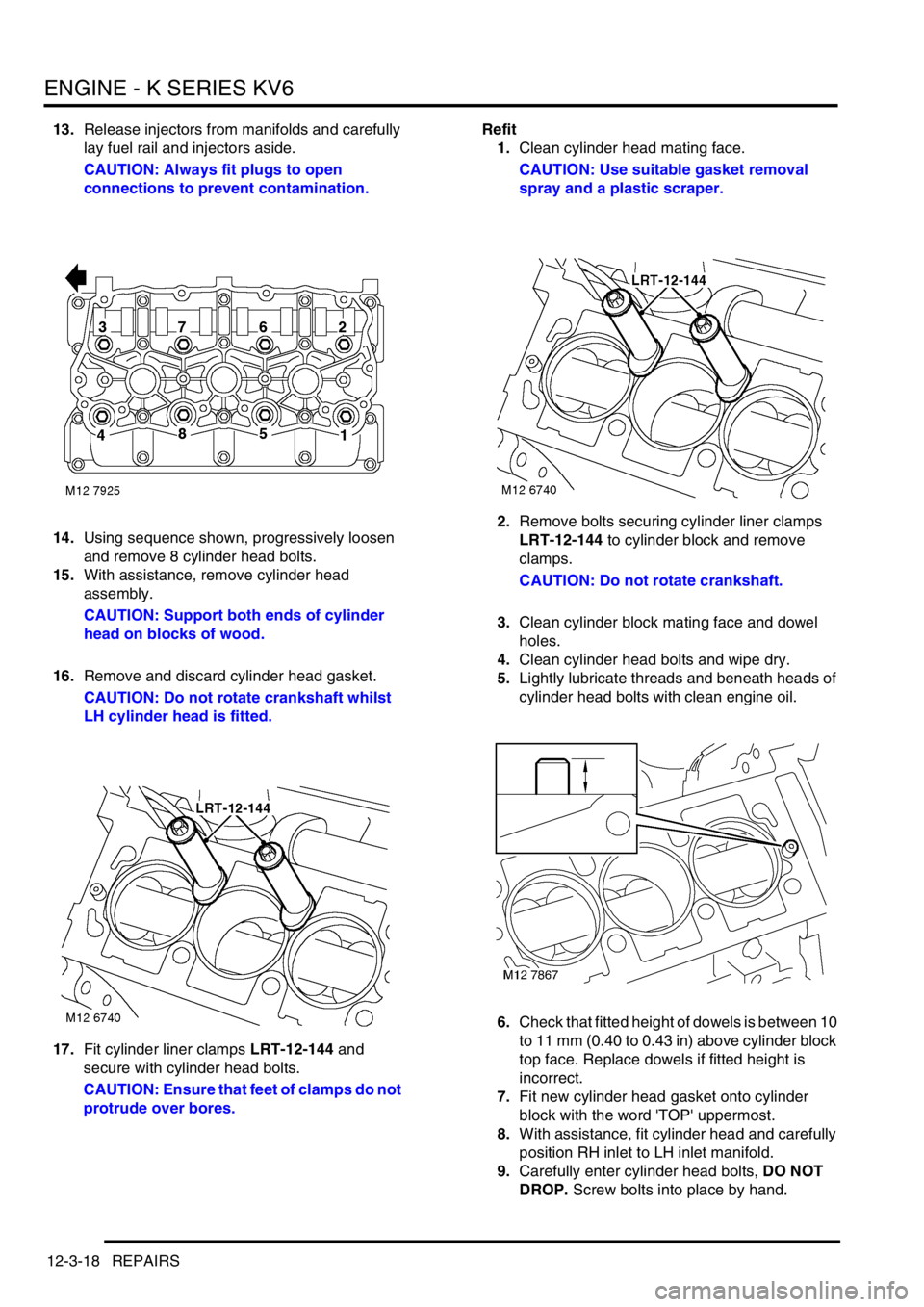
14.Using sequence shown, progressively loosen
and remove 8 cylinder head bolts.
15.With assistance, remove cylinder head
assembly.
CAUTION: Support both ends of cylinder
head on blocks of wood.
16.Remove and discard cylinder head gasket.
CAUTION: Do not rotate crankshaft whilst
LH cylinder head is fitted.
17.Fit cylinder liner clamps LRT-12-144 and
secure with cylinder head bolts.
CAUTION: Ensure that feet of clamps do not
protrude over bores.Refit
1.Clean cylinder head mating face.
CAUTION: Use suitable gasket removal
spray and a plastic scraper.
2.Remove bolts securing cylinder liner clamps
LRT-12-144 to cylinder block and remove
clamps.
CAUTION: Do not rotate crankshaft.
3.Clean cylinder block mating face and dowel
holes.
4.Clean cylinder head bolts and wipe dry.
5.Lightly lubricate threads and beneath heads of
cylinder head bolts with clean engine oil.
6.Check that fitted height of dowels is between 10
to 11 mm (0.40 to 0.43 in) above cylinder block
top face. Replace dowels if fitted height is
incorrect.
7.Fit new cylinder head gasket onto cylinder
block with the word 'TOP' uppermost.
8.With assistance, fit cylinder head and carefully
position RH inlet to LH inlet manifold.
9.Carefully enter cylinder head bolts, DO NOT
DROP. Screw bolts into place by hand.
Page 233 of 1007
ENGINE - K SERIES KV6
12-3-56 REPAIRS
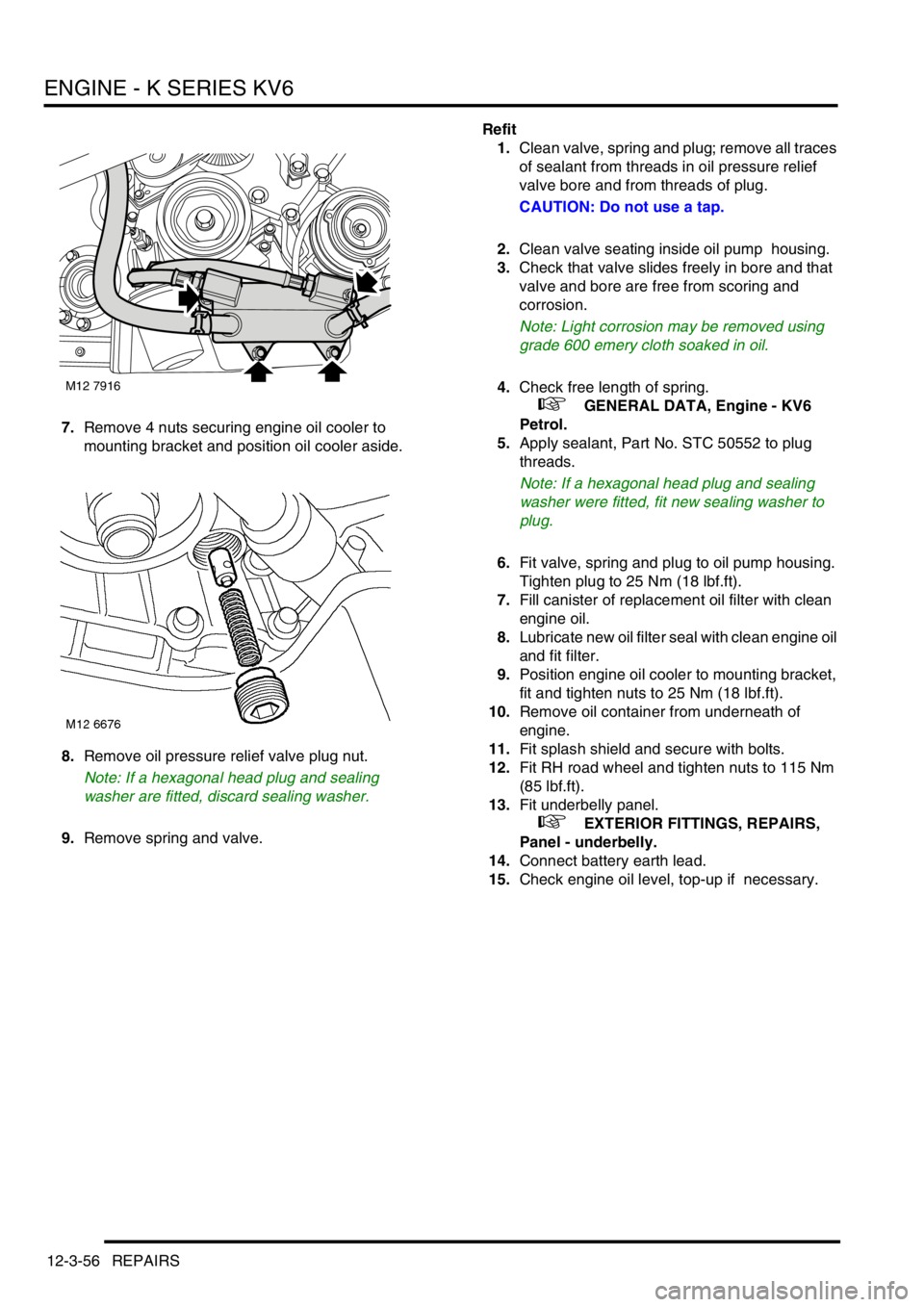
7.Remove 4 nuts securing engine oil cooler to
mounting bracket and position oil cooler aside.
8.Remove oil pressure relief valve plug nut.
Note: If a hexagonal head plug and sealing
washer are fitted, discard sealing washer.
9.Remove spring and valve.Refit
1.Clean valve, spring and plug; remove all traces
of sealant from threads in oil pressure relief
valve bore and from threads of plug.
CAUTION: Do not use a tap.
2.Clean valve seating inside oil pump housing.
3.Check that valve slides freely in bore and that
valve and bore are free from scoring and
corrosion.
Note: Light corrosion may be removed using
grade 600 emery cloth soaked in oil.
4.Check free length of spring.
+ GENERAL DATA, Engine - KV6
Petrol.
5.Apply sealant, Part No. STC 50552 to plug
threads.
Note: If a hexagonal head plug and sealing
washer were fitted, fit new sealing washer to
plug.
6.Fit valve, spring and plug to oil pump housing.
Tighten plug to 25 Nm (18 lbf.ft).
7.Fill canister of replacement oil filter with clean
engine oil.
8.Lubricate new oil filter seal with clean engine oil
and fit filter.
9.Position engine oil cooler to mounting bracket,
fit and tighten nuts to 25 Nm (18 lbf.ft).
10.Remove oil container from underneath of
engine.
11.Fit splash shield and secure with bolts.
12.Fit RH road wheel and tighten nuts to 115 Nm
(85 lbf.ft).
13.Fit underbelly panel.
+ EXTERIOR FITTINGS, REPAIRS,
Panel - underbelly.
14.Connect battery earth lead.
15.Check engine oil level, top-up if necessary.
M12 7916
Page 241 of 1007
ENGINE - K SERIES KV6
12-3-64 REPAIRS
Refit
NOTE: Following front or rear timing belt
refitment, it is possible that, after rotating the
engine and positioning the crankshaft pulley to
the 'SAFE' position, the timing marks on the
rear timing gears may be misaligned. This
misalignment is acceptable provided that the
timing belt refitting procedure was carried out
correctly.
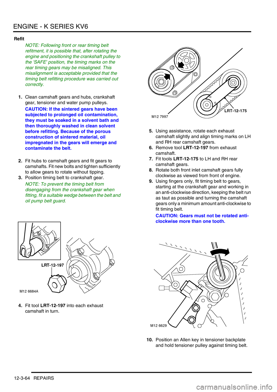
1.Clean camshaft gears and hubs, crankshaft
gear, tensioner and water pump pulleys.
CAUTION: If the sintered gears have been
subjected to prolonged oil contamination,
they must be soaked in a solvent bath and
then thoroughly washed in clean solvent
before refitting. Because of the porous
construction of sintered material, oil
impregnated in the gears will emerge and
contaminate the belt.
2.Fit hubs to camshaft gears and fit gears to
camshafts. Fit new bolts and tighten sufficiently
to allow gears to rotate without tipping.
3.Position timing belt to crankshaft gear.
NOTE: To prevent the timing belt from
disengaging from the crankshaft gear when
fitting, fit a suitable wedge between the belt and
oil pump belt guard.
4.Fit tool LRT-12-197 into each exhaust
camshaft in turn.5.Using assistance, rotate each exhaust
camshaft slightly and align timing marks on LH
and RH rear camshaft gears.
6.Remove tool LRT-12-197 from exhaust
camshaft.
7.Fit tools LRT-12-175 to LH and RH rear
camshaft gears.
8.Rotate both front inlet camshaft gears fully
clockwise as viewed from front of engine.
9.Using fingers only, fit timing belt to gears,
starting at the crankshaft gear and working in
an anti-clockwise direction, keeping the belt run
as taut as possible and turning the camshaft
gears only a minimum amount anti-clockwise to
fit timing belt.
CAUTION: Gears must not be rotated anti-
clockwise more than one tooth.
10.Position an Allen key in tensioner backplate
and hold tensioner pulley against timing belt.
Page 254 of 1007
ENGINE - K SERIES KV6
OVERHAUL 12-3-77
OVERHAUL
Piston assemblies - engine set
$% 12.17.03.01
Disassembly
1.Remove crankshaft.
+ ENGINE - K SERIES KV6,
OVERHAUL, Crankshaft.
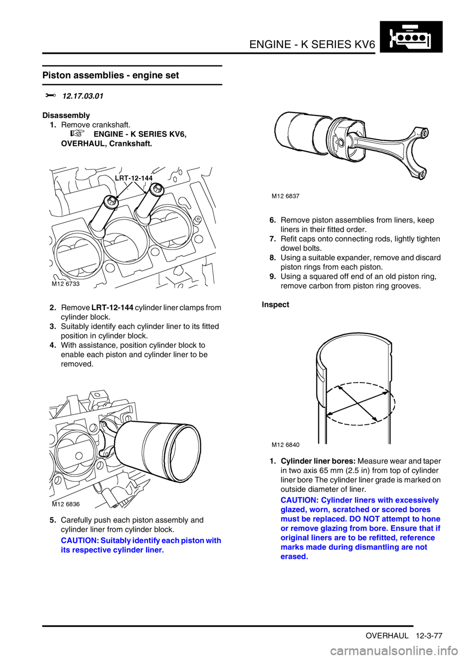
2.Remove LRT-12-144 cylinder liner clamps from
cylinder block.
3.Suitably identify each cylinder liner to its fitted
position in cylinder block.
4.With assistance, position cylinder block to
enable each piston and cylinder liner to be
removed.
5.Carefully push each piston assembly and
cylinder liner from cylinder block.
CAUTION: Suitably identify each piston with
its respective cylinder liner.6.Remove piston assemblies from liners, keep
liners in their fitted order.
7.Refit caps onto connecting rods, lightly tighten
dowel bolts.
8.Using a suitable expander, remove and discard
piston rings from each piston.
9.Using a squared off end of an old piston ring,
remove carbon from piston ring grooves.
Inspect
1. Cylinder liner bores: Measure wear and taper
in two axis 65 mm (2.5 in) from top of cylinder
liner bore The cylinder liner grade is marked on
outside diameter of liner.
CAUTION: Cylinder liners with excessively
glazed, worn, scratched or scored bores
must be replaced. DO NOT attempt to hone
or remove glazing from bore. Ensure that if
original liners are to be refitted, reference
marks made during dismantling are not
erased.
Page 262 of 1007
ENGINE - K SERIES KV6
OVERHAUL 12-3-85
9. Big-end bearings selection: Select the
required bearing shells from general data.
+ GENERAL DATA, Engine - KV6
Petrol.
10.Ensure all bolt holes are clean and dry.
Remove all traces of thread locking material
from oil pick-up strainer bolt hole and threads of
retaining bolt.
CAUTION: Do not use a tap.
11.Ensure bearing ladder locating dowels are
fitted and dowel holes in bearing ladder are
clean and dry.
12.Check coolant stub pipe in cylinder block for
signs of leakage and corrosion, replace as
necessary. Apply sealant, Part No. STC 50554
to seal replacement pipe to cylinder block.
13.Clean main bearing shell recesses in cylinder
block.
14.Clean crankshaft main bearing and big end
bearing journals. Clean bearing shell locations
in connecting rods and caps.
15.Fit selected main bearing shells, grooved into
cylinder block and plain into bearing ladder.
16.Fit new thrust washers to cylinder block.
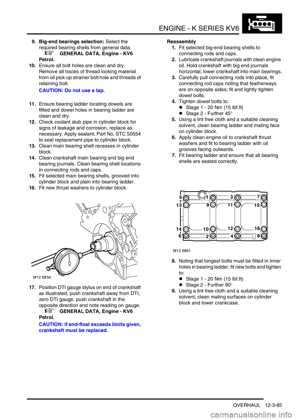
17.Position DTI gauge stylus on end of crankshaft
as illustrated, push crankshaft away from DTI,
zero DTI gauge, push crankshaft in the
opposite direction and note reading on gauge.
+ GENERAL DATA, Engine - KV6
Petrol.
CAUTION: If end-float exceeds limits given,
crankshaft must be replaced.Reassembly
1.Fit selected big-end bearing shells to
connecting rods and caps.
2.Lubricate crankshaft journals with clean engine
oil. Hold crankshaft with big end journals
horizontal, lower crankshaft into main bearings.
3.Carefully pull connecting rods into place, fit
connecting rod caps noting that featherways
are on opposite sides; fit and lightly tighten
dowel bolts.
4.Tighten dowel bolts to:
lStage 1 - 20 Nm (15 lbf.ft)
lStage 2 - Further 45°
5.Using a lint free cloth and a suitable cleaning
solvent, clean bearing ladder and mating face
on cylinder block.
6.Apply clean engine oil to crankshaft thrust
washers and fit to bearing ladder with oil
grooves facing outwards.
7.Fit bearing ladder and ensure that all bearing
shells are seated correctly.
8.Noting that longest bolts must be fitted in inner
holes in bearing ladder, fit new bolts and tighten
to:
lStage 1 - 20 Nm (15 lbf.ft)
lStage 2 - Further 90°
9.Using a lint free cloth and a suitable cleaning
solvent, clean mating surfaces on cylinder
block and lower crankcase.
Page 263 of 1007
ENGINE - K SERIES KV6
12-3-86 OVERHAUL
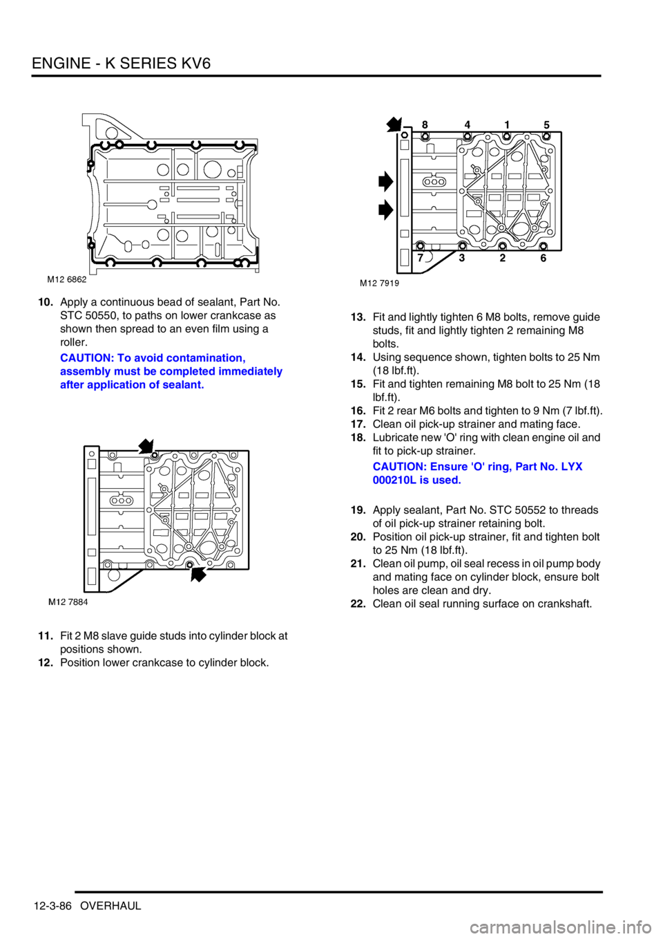
10.Apply a continuous bead of sealant, Part No.
STC 50550, to paths on lower crankcase as
shown then spread to an even film using a
roller.
CAUTION: To avoid contamination,
assembly must be completed immediately
after application of sealant.
11.Fit 2 M8 slave guide studs into cylinder block at
positions shown.
12.Position lower crankcase to cylinder block.13.Fit and lightly tighten 6 M8 bolts, remove guide
studs, fit and lightly tighten 2 remaining M8
bolts.
14.Using sequence shown, tighten bolts to 25 Nm
(18 lbf.ft).
15.Fit and tighten remaining M8 bolt to 25 Nm (18
lbf.ft).
16.Fit 2 rear M6 bolts and tighten to 9 Nm (7 lbf.ft).
17.Clean oil pick-up strainer and mating face.
18.Lubricate new 'O' ring with clean engine oil and
fit to pick-up strainer.
CAUTION: Ensure 'O' ring, Part No. LYX
000210L is used.
19.Apply sealant, Part No. STC 50552 to threads
of oil pick-up strainer retaining bolt.
20.Position oil pick-up strainer, fit and tighten bolt
to 25 Nm (18 lbf.ft).
21.Clean oil pump, oil seal recess in oil pump body
and mating face on cylinder block, ensure bolt
holes are clean and dry.
22.Clean oil seal running surface on crankshaft.
Page 266 of 1007
ENGINE - K SERIES KV6
OVERHAUL 12-3-89
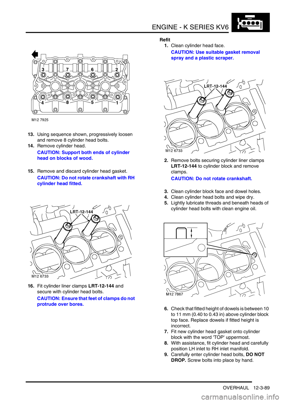
13.Using sequence shown, progressively loosen
and remove 8 cylinder head bolts.
14.Remove cylinder head.
CAUTION: Support both ends of cylinder
head on blocks of wood.
15.Remove and discard cylinder head gasket.
CAUTION: Do not rotate crankshaft with RH
cylinder head fitted.
16.Fit cylinder liner clamps LRT-12-144 and
secure with cylinder head bolts.
CAUTION: Ensure that feet of clamps do not
protrude over bores.Refit
1.Clean cylinder head face.
CAUTION: Use suitable gasket removal
spray and a plastic scraper.
2.Remove bolts securing cylinder liner clamps
LRT-12-144 to cylinder block and remove
clamps.
CAUTION: Do not rotate crankshaft.
3.Clean cylinder block face and dowel holes.
4.Clean cylinder head bolts and wipe dry.
5.Lightly lubricate threads and beneath heads of
cylinder head bolts with clean engine oil.
6.Check that fitted height of dowels is between 10
to 11 mm (0.40 to 0.43 in) above cylinder block
top face. Replace dowels if fitted height is
incorrect.
7.Fit new cylinder head gasket onto cylinder
block with the word 'TOP' uppermost.
8.With assistance, fit cylinder head and carefully
position LH inlet to RH inlet manifold.
9.Carefully enter cylinder head bolts, DO NOT
DROP. Screw bolts into place by hand.
Page 270 of 1007
ENGINE - K SERIES KV6
OVERHAUL 12-3-93
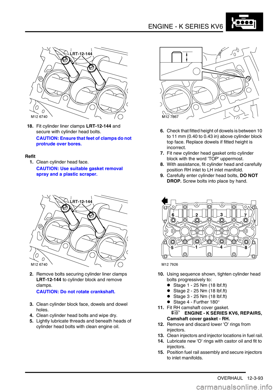
18.Fit cylinder liner clamps LRT-12-144 and
secure with cylinder head bolts.
CAUTION: Ensure that feet of clamps do not
protrude over bores.
Refit
1.Clean cylinder head face.
CAUTION: Use suitable gasket removal
spray and a plastic scraper.
2.Remove bolts securing cylinder liner clamps
LRT-12-144 to cylinder block and remove
clamps.
CAUTION: Do not rotate crankshaft.
3.Clean cylinder block face, dowels and dowel
holes.
4.Clean cylinder head bolts and wipe dry.
5.Lightly lubricate threads and beneath heads of
cylinder head bolts with clean engine oil.6.Check that fitted height of dowels is between 10
to 11 mm (0.40 to 0.43 in) above cylinder block
top face. Replace dowels if fitted height is
incorrect.
7.Fit new cylinder head gasket onto cylinder
block with the word 'TOP' uppermost.
8.With assistance, fit cylinder head and carefully
position RH inlet to LH inlet manifold.
9.Carefully enter cylinder head bolts, DO NOT
DROP. Screw bolts into place by hand.
10.Using sequence shown, tighten cylinder head
bolts progressively to:
lStage 1 - 25 Nm (18 lbf.ft)
lStage 2 - 25 Nm (18 lbf.ft)
lStage 3 - 25 Nm (18 lbf.ft)
lStage 4 - Further 180°
11.Fit RH camshaft cover gasket.
+ ENGINE - K SERIES KV6, REPAIRS,
Camshaft cover gasket - RH.
12.Remove and discard lower 'O' rings from
injectors.
13.Clean injectors and injector locations in fuel rail.
14.Lubricate new 'O' rings with castor oil and fit to
injectors.
15.Position fuel rail assembly and secure injectors
to inlet manifolds.