light LAND ROVER FREELANDER 2001 User Guide
[x] Cancel search | Manufacturer: LAND ROVER, Model Year: 2001, Model line: FREELANDER, Model: LAND ROVER FREELANDER 2001Pages: 1007, PDF Size: 23.47 MB
Page 48 of 1007
GENERAL INFORMATION
03-17
SPX Corporation,
665, Eisenhower Drive,
Owatonna,
MN 55060,
USA
( 0018 772979110
) 0018 005787375
Australia
SPX Australia,
28, Clayton Road,
Notting Hill,
Victoria 3168,
Australia
( 00 (61) 00395446222
) 00 (61) 0395445222
e-mail: [email protected]
Japan and East Asia
Jatek Ltd.,
5 - 53, Minawacho 2-chome,
Kohoku-ku,
Yokohama,
Kanagawa 223-0051,
Japan
( 0081 455627700
) 0081 455627800
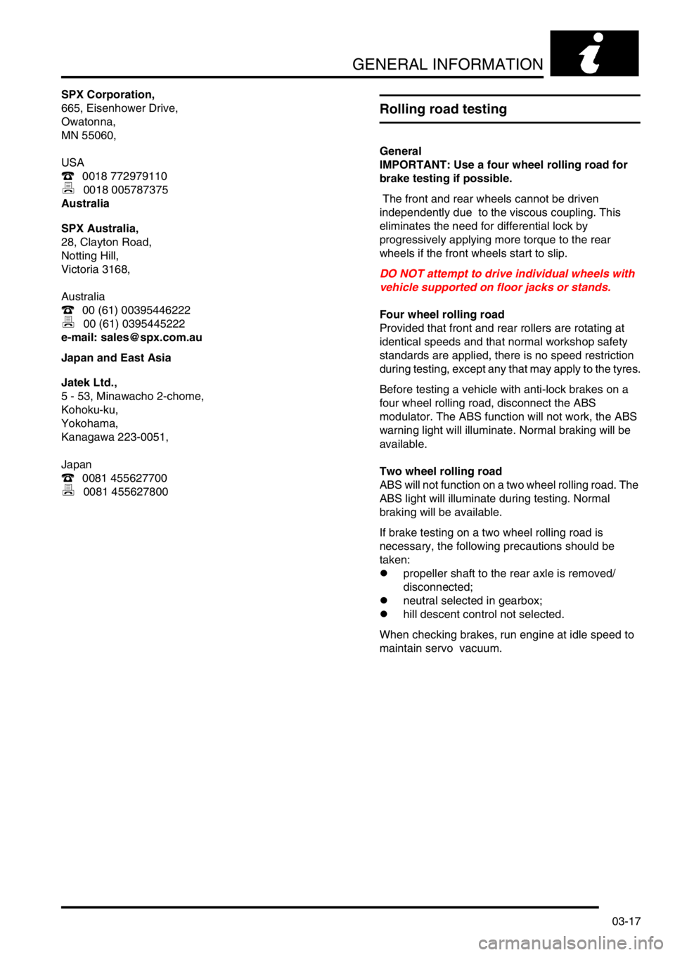
Rolling road testing
General
IMPORTANT: Use a four wheel rolling road for
brake testing if possible.
The front and rear wheels cannot be driven
independently due to the viscous coupling. This
eliminates the need for differential lock by
progressively applying more torque to the rear
wheels if the front wheels start to slip.
DO NOT attempt to drive individual wheels with
vehicle supported on floor jacks or stands.
Four wheel rolling road
Provided that front and rear rollers are rotating at
identical speeds and that normal workshop safety
standards are applied, there is no speed restriction
during testing, except any that may apply to the tyres.
Before testing a vehicle with anti-lock brakes on a
four wheel rolling road, disconnect the ABS
modulator. The ABS function will not work, the ABS
warning light will illuminate. Normal braking will be
available.
Two wheel rolling road
ABS will not function on a two wheel rolling road. The
ABS light will illuminate during testing. Normal
braking will be available.
If brake testing on a two wheel rolling road is
necessary, the following precautions should be
taken:
lpropeller shaft to the rear axle is removed/
disconnected;
lneutral selected in gearbox;
lhill descent control not selected.
When checking brakes, run engine at idle speed to
maintain servo vacuum.
Page 49 of 1007
GENERAL INFORMATION
03-18
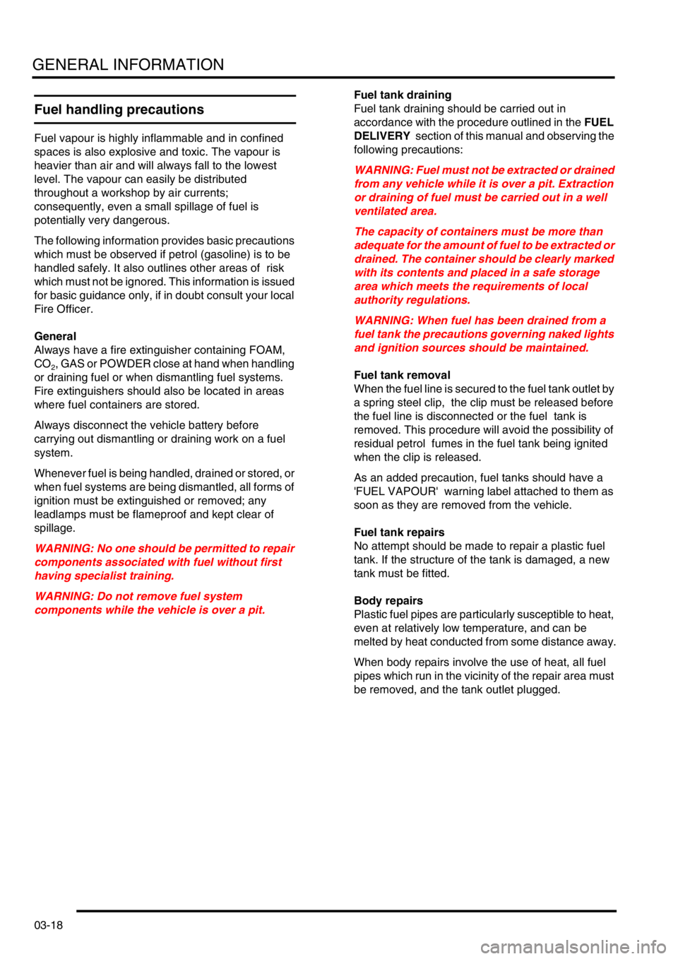
Fuel handling precautions
Fuel vapour is highly inflammable and in confined
spaces is also explosive and toxic. The vapour is
heavier than air and will always fall to the lowest
level. The vapour can easily be distributed
throughout a workshop by air currents;
consequently, even a small spillage of fuel is
potentially very dangerous.
The following information provides basic precautions
which must be observed if petrol (gasoline) is to be
handled safely. It also outlines other areas of risk
which must not be ignored. This information is issued
for basic guidance only, if in doubt consult your local
Fire Officer.
General
Always have a fire extinguisher containing FOAM,
CO
2, GAS or POWDER close at hand when handling
or draining fuel or when dismantling fuel systems.
Fire extinguishers should also be located in areas
where fuel containers are stored.
Always disconnect the vehicle battery before
carrying out dismantling or draining work on a fuel
system.
Whenever fuel is being handled, drained or stored, or
when fuel systems are being dismantled, all forms of
ignition must be extinguished or removed; any
leadlamps must be flameproof and kept clear of
spillage.
WARNING: No one should be permitted to repair
components associated with fuel without first
having specialist training.
WARNING: Do not remove fuel system
components while the vehicle is over a pit.Fuel tank draining
Fuel tank draining should be carried out in
accordance with the procedure outlined in the FUEL
DELIVERY section of this manual and observing the
following precautions:
WARNING: Fuel must not be extracted or drained
from any vehicle while it is over a pit. Extraction
or draining of fuel must be carried out in a well
ventilated area.
The capacity of containers must be more than
adequate for the amount of fuel to be extracted or
drained. The container should be clearly marked
with its contents and placed in a safe storage
area which meets the requirements of local
authority regulations.
WARNING: When fuel has been drained from a
fuel tank the precautions governing naked lights
and ignition sources should be maintained.
Fuel tank removal
When the fuel line is secured to the fuel tank outlet by
a spring steel clip, the clip must be released before
the fuel line is disconnected or the fuel tank is
removed. This procedure will avoid the possibility of
residual petrol fumes in the fuel tank being ignited
when the clip is released.
As an added precaution, fuel tanks should have a
'FUEL VAPOUR' warning label attached to them as
soon as they are removed from the vehicle.
Fuel tank repairs
No attempt should be made to repair a plastic fuel
tank. If the structure of the tank is damaged, a new
tank must be fitted.
Body repairs
Plastic fuel pipes are particularly susceptible to heat,
even at relatively low temperature, and can be
melted by heat conducted from some distance away.
When body repairs involve the use of heat, all fuel
pipes which run in the vicinity of the repair area must
be removed, and the tank outlet plugged.
Page 69 of 1007
GENERAL DATA
04-6
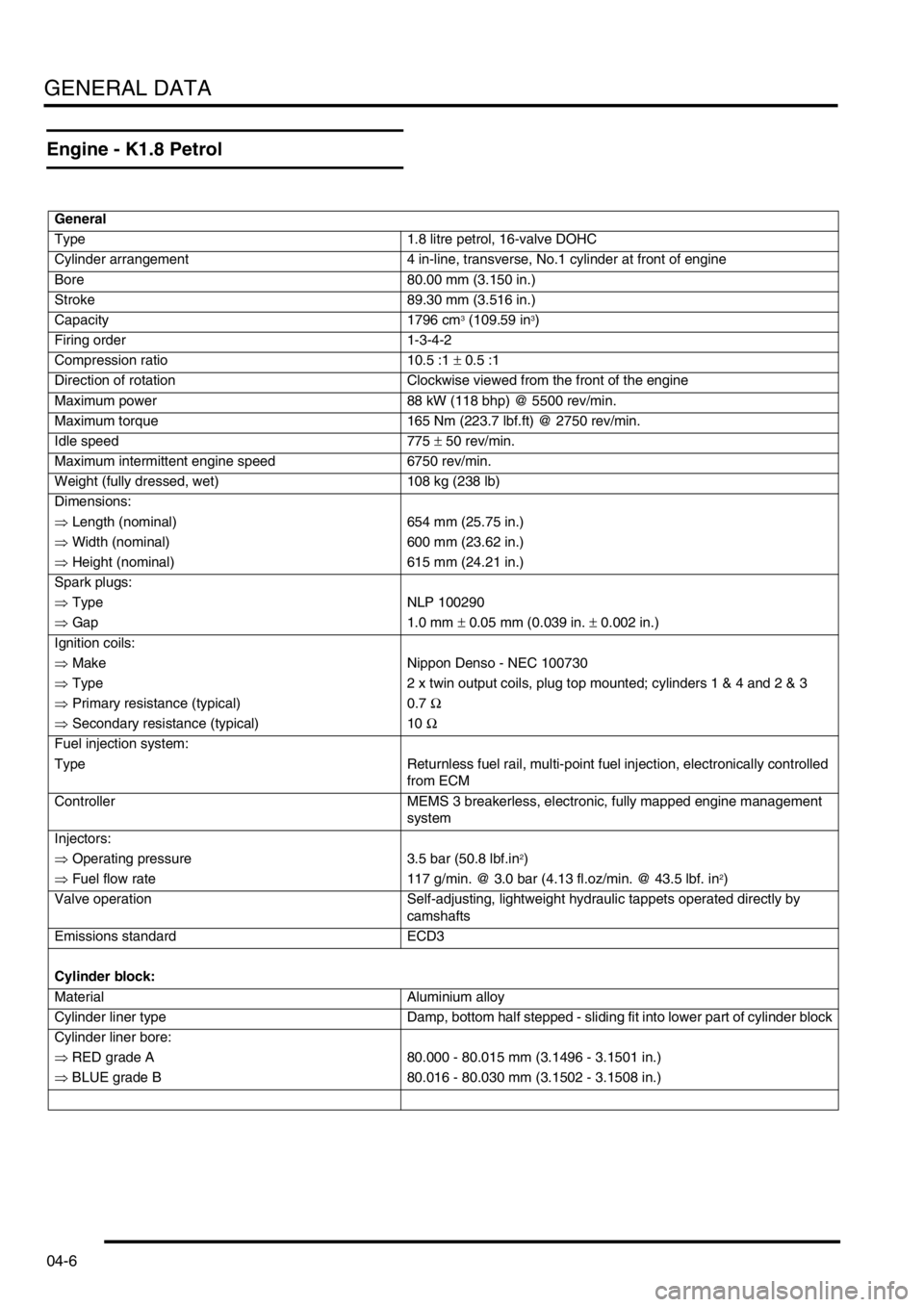
Engine - K1.8 Petrol
General
Type 1.8 litre petrol, 16-valve DOHC
Cylinder arrangement 4 in-line, transverse, No.1 cylinder at front of engine
Bore 80.00 mm (3.150 in.)
Stroke 89.30 mm (3.516 in.)
Capacity 1796 cm
3 (109.59 in3)
Firing order 1-3-4-2
Compression ratio 10.5 :1 ± 0.5 :1
Direction of rotation Clockwise viewed from the front of the engine
Maximum power 88 kW (118 bhp) @ 5500 rev/min.
Maximum torque 165 Nm (223.7 lbf.ft) @ 2750 rev/min.
Idle speed 775 ± 50 rev/min.
Maximum intermittent engine speed 6750 rev/min.
Weight (fully dressed, wet) 108 kg (238 lb)
Dimensions:
⇒ Length (nominal) 654 mm (25.75 in.)
⇒ Width (nominal) 600 mm (23.62 in.)
⇒ Height (nominal) 615 mm (24.21 in.)
Spark plugs:
⇒ Type NLP 100290
⇒ Gap 1.0 mm ± 0.05 mm (0.039 in. ± 0.002 in.)
Ignition coils:
⇒ Make Nippon Denso - NEC 100730
⇒ Type 2 x twin output coils, plug top mounted; cylinders 1 & 4 and 2 & 3
⇒ Primary resistance (typical) 0.7 Ω
⇒ Secondary resistance (typical) 10 Ω
Fuel injection system:
Type Returnless fuel rail, multi-point fuel injection, electronically controlled
from ECM
Controller MEMS 3 breakerless, electronic, fully mapped engine management
system
Injectors:
⇒ Operating pressure 3.5 bar (50.8 lbf.in
2)
⇒ Fuel flow rate 117 g/min. @ 3.0 bar (4.13 fl.oz/min. @ 43.5 lbf. in
2)
Valve operation Self-adjusting, lightweight hydraulic tappets operated directly by
camshafts
Emissions standard ECD3
Cylinder block:
Material Aluminium alloy
Cylinder liner type Damp, bottom half stepped - sliding fit into lower part of cylinder block
Cylinder liner bore:
⇒ RED grade A 80.000 - 80.015 mm (3.1496 - 3.1501 in.)
⇒ BLUE grade B 80.016 - 80.030 mm (3.1502 - 3.1508 in.)
Page 71 of 1007

GENERAL DATA
04-8
Pistons
Type Aluminium alloy, tin plated, thermal expansion with offset gudgeon pin
Piston diameter:
⇒ Grade A 79.975 - 79.990 mm (3.1486 - 3.1492 in.)
⇒ Grade B 79.991 - 80.005 mm (3.1492 - 3.1498 in.)
Clearance in bore 0.01 - 0.04 mm (0.0004 - 0.0016 in.)
Maximum ovality 0.30 mm (0.012 in.)
Piston rings:
Type: 2 compression, 1 oil control
⇒ Top compression ring Barrel faced, granulite coated
⇒ 2nd compression ring Tapered, phosphate coated
⇒ Oil control ring Nitrided ring with radii and spring
New ring to groove clearance:
⇒ Top compression ring 0.040 - 0.072 mm (0.0016 - 0.0028 in.)
⇒ 2nd compression ring 0.030 - 0.062 mm (0.0012 - 0.0024 in.)
⇒ Oil control ring 0.010 - 0.180 mm (0.0004 - 0.0071 in.)
Ring fitted gap 20 mm (0.75 in) from top of bore:
⇒ Top compression ring 0.20 - 0.35 mm (0.008 - 0.014 in.)
⇒ 2nd compression ring 0.28 - 0.48 mm (0.011 - 0.019 in.)
⇒ Oil control ring 0.15 - 0.40 mm (0.006 - 0.016 in.)
Piston ring width:
⇒ Top compression ring 0.978 - 0.990 mm (0.0385 - 0.0390 in.)
⇒ 2nd compression ring 1.178 - 1.190 mm (0.0464 - 0.0469 in.)
⇒ Oil control ring 0.33 - 0.38 mm (0.0130 - 0.0150 in.)
Camshaft
Type DOHC acting directly on tappets, incorporates target/reluctor for
camshaft sensor
Bearings 6 per camshaft, direct line bored
Drive Toothed belt driven from crankshaft gear, automatically tensioned
Camshaft end-float 0.06 - 0.19 mm (0.002 - 0.007 in.)
⇒ Service limit 0.30 mm (0.012 in.)
Bearing clearance 0.060 - 0.094 mm (0.0024 - 0.0037 in.)
⇒ Service limit 0.15 mm (0.006 in.)
Tappets
Type Self-adjusting lightweight hydraulic tappets, operated directly from
camshafts
Tappet outside diameter 32.959 - 32.975 mm (1.2976 - 1.2982 in.)
Valve timing:
Inlet valves:
⇒ Opens
⇒ Closes
⇒ Maximum lift12° BTDC
52° ABDC
8.8 mm (0.35 in.)
Exhaust valves:
⇒ Opens
⇒ Closes
⇒ Maximum lift52° BBDC
12° ATDC
8.8 mm (0.35 in.) General
Page 74 of 1007
GENERAL DATA
04-11
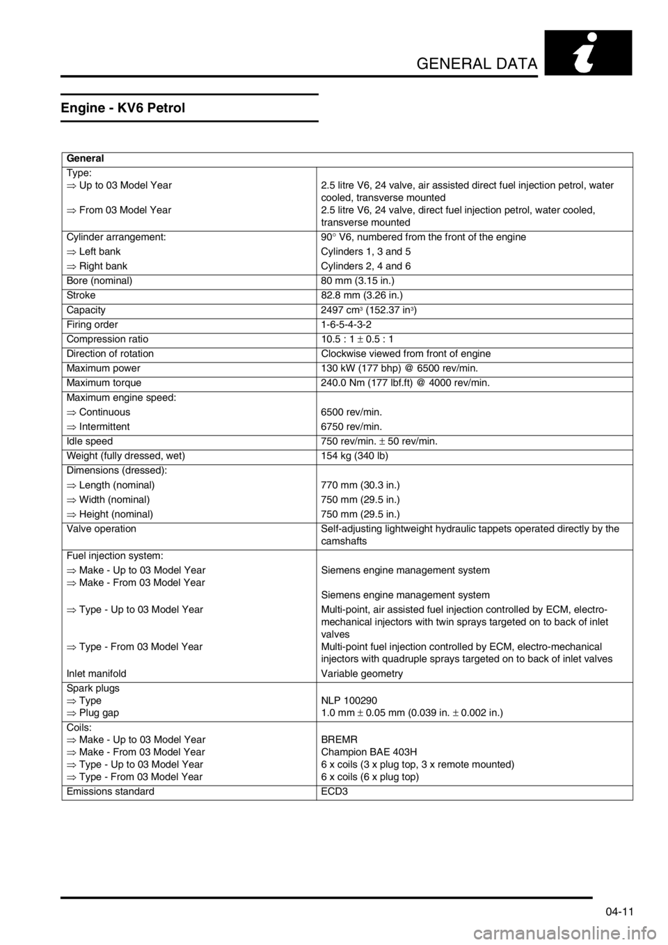
Engine - KV6 Petrol
General
Type:
⇒ Up to 03 Model Year
⇒ From 03 Model Year2.5 litre V6, 24 valve, air assisted direct fuel injection petrol, water
cooled, transverse mounted
2.5 litre V6, 24 valve, direct fuel injection petrol, water cooled,
transverse mounted
Cylinder arrangement: 90° V6, numbered from the front of the engine
⇒ Left bank Cylinders 1, 3 and 5
⇒ Right bank Cylinders 2, 4 and 6
Bore (nominal) 80 mm (3.15 in.)
Stroke 82.8 mm (3.26 in.)
Capacity 2497 cm
3 (152.37 in3)
Firing order 1-6-5-4-3-2
Compression ratio 10.5 : 1 ± 0.5 : 1
Direction of rotation Clockwise viewed from front of engine
Maximum power 130 kW (177 bhp) @ 6500 rev/min.
Maximum torque 240.0 Nm (177 lbf.ft) @ 4000 rev/min.
Maximum engine speed:
⇒ Continuous 6500 rev/min.
⇒ Intermittent 6750 rev/min.
Idle speed 750 rev/min. ± 50 rev/min.
Weight (fully dressed, wet) 154 kg (340 lb)
Dimensions (dressed):
⇒ Length (nominal) 770 mm (30.3 in.)
⇒ Width (nominal) 750 mm (29.5 in.)
⇒ Height (nominal) 750 mm (29.5 in.)
Valve operation Self-adjusting lightweight hydraulic tappets operated directly by the
camshafts
Fuel injection system:
⇒ Make - Up to 03 Model Year
⇒ Make - From 03 Model YearSiemens engine management system
Siemens engine management system
⇒ Type - Up to 03 Model Year
⇒ Type - From 03 Model YearMulti-point, air assisted fuel injection controlled by ECM, electro-
mechanical injectors with twin sprays targeted on to back of inlet
valves
Multi-point fuel injection controlled by ECM, electro-mechanical
injectors with quadruple sprays targeted on to back of inlet valves
Inlet manifold Variable geometry
Spark plugs
⇒ Type
⇒ Plug gapNLP 100290
1.0 mm ± 0.05 mm (0.039 in. ± 0.002 in.)
Coils:
⇒ Make - Up to 03 Model Year
⇒ Make - From 03 Model Year
⇒ Type - Up to 03 Model Year
⇒ Type - From 03 Model YearBREMR
Champion BAE 403H
6 x coils (3 x plug top, 3 x remote mounted)
6 x coils (6 x plug top)
Emissions standard ECD3
Page 122 of 1007
TORQUE WRENCH SETTINGS
06-19
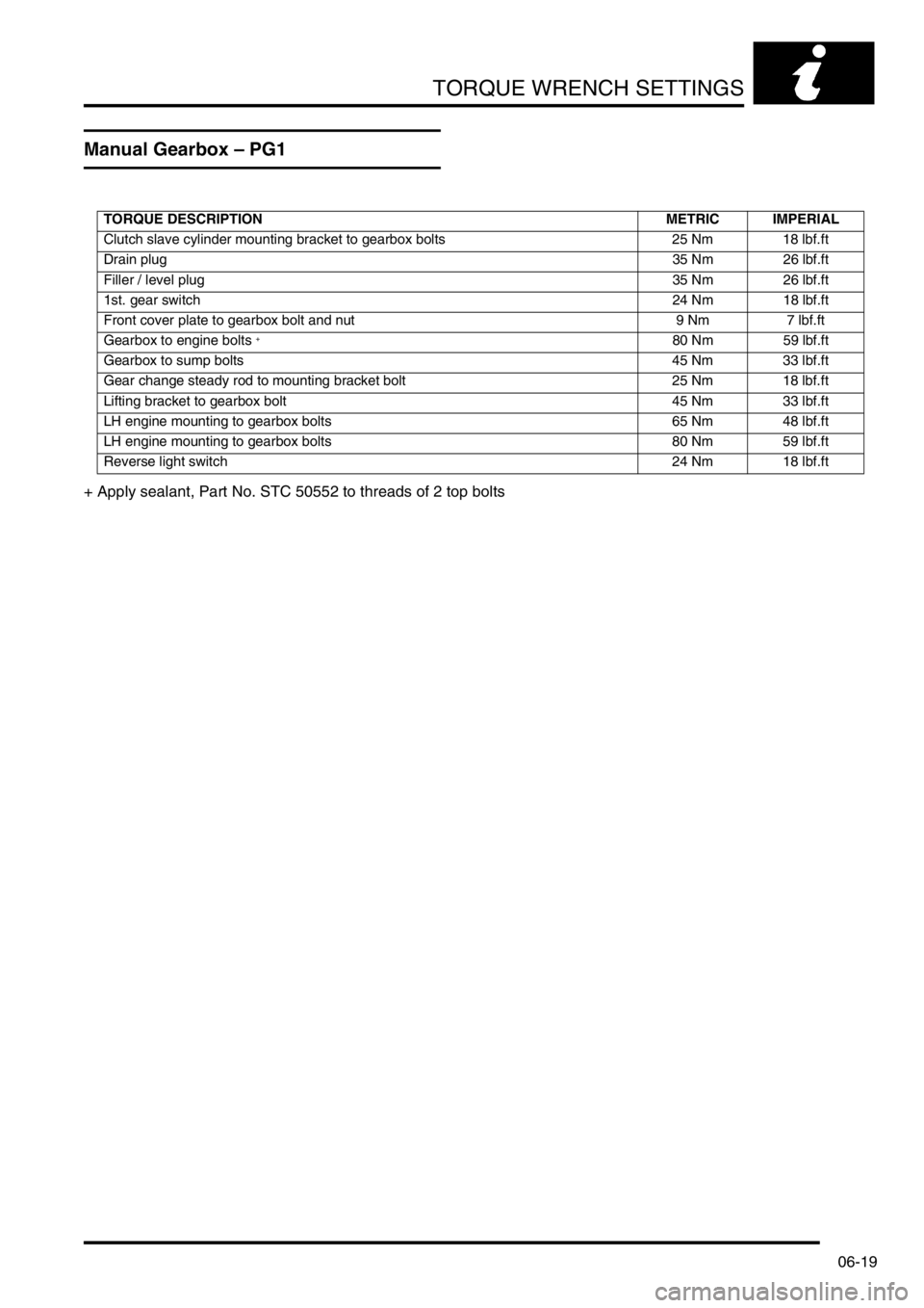
Manual Gearbox – PG1
+ Apply sealant, Part No. STC 50552 to threads of 2 top bolts
TORQUE DESCRIPTION METRIC IMPERIAL
Clutch slave cylinder mounting bracket to gearbox bolts 25 Nm 18 lbf.ft
Drain plug35 Nm 26 lbf.ft
Filler / level plug35 Nm 26 lbf.ft
1st. gear switch24 Nm 18 lbf.ft
Front cover plate to gearbox bolt and nut 9 Nm 7 lbf.ft
Gearbox to engine bolts
+80 Nm 59 lbf.ft
Gearbox to sump bolts 45 Nm 33 lbf.ft
Gear change steady rod to mounting bracket bolt 25 Nm 18 lbf.ft
Lifting bracket to gearbox bolt 45 Nm 33 lbf.ft
LH engine mounting to gearbox bolts 65 Nm 48 lbf.ft
LH engine mounting to gearbox bolts 80 Nm 59 lbf.ft
Reverse light switch 24 Nm 18 lbf.ft
Page 141 of 1007
LIFTING AND TOWING
08-2
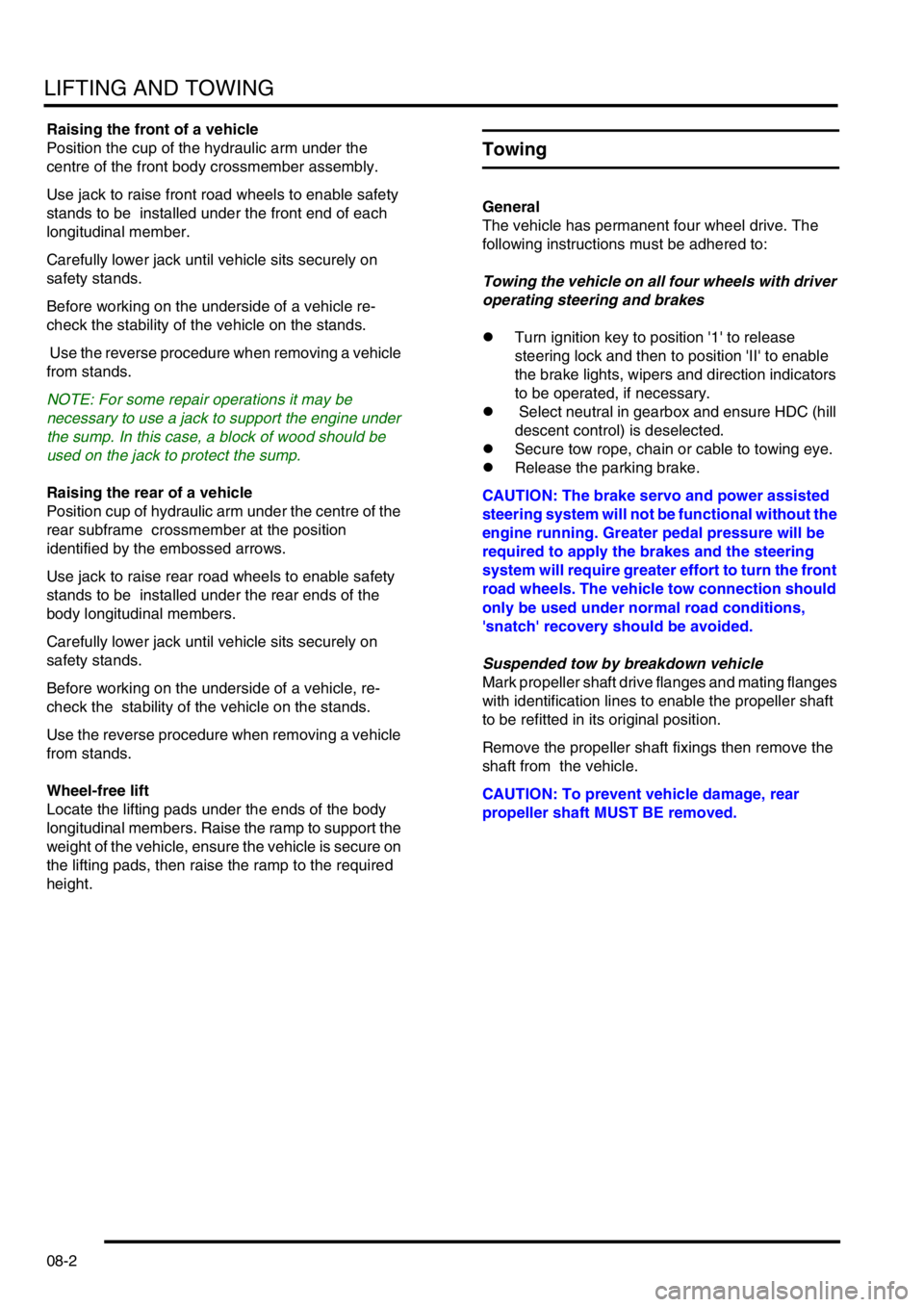
Raising the front of a vehicle
Position the cup of the hydraulic arm under the
centre of the front body crossmember assembly.
Use jack to raise front road wheels to enable safety
stands to be installed under the front end of each
longitudinal member.
Carefully lower jack until vehicle sits securely on
safety stands.
Before working on the underside of a vehicle re-
check the stability of the vehicle on the stands.
Use the reverse procedure when removing a vehicle
from stands.
NOTE: For some repair operations it may be
necessary to use a jack to support the engine under
the sump. In this case, a block of wood should be
used on the jack to protect the sump.
Raising the rear of a vehicle
Position cup of hydraulic arm under the centre of the
rear subframe crossmember at the position
identified by the embossed arrows.
Use jack to raise rear road wheels to enable safety
stands to be installed under the rear ends of the
body longitudinal members.
Carefully lower jack until vehicle sits securely on
safety stands.
Before working on the underside of a vehicle, re-
check the stability of the vehicle on the stands.
Use the reverse procedure when removing a vehicle
from stands.
Wheel-free lift
Locate the lifting pads under the ends of the body
longitudinal members. Raise the ramp to support the
weight of the vehicle, ensure the vehicle is secure on
the lifting pads, then raise the ramp to the required
height.
Towing
General
The vehicle has permanent four wheel drive. The
following instructions must be adhered to:
Towing the vehicle on all four wheels with driver
operating steering and brakes
lTurn ignition key to position '1' to release
steering lock and then to position 'II' to enable
the brake lights, wipers and direction indicators
to be operated, if necessary.
l Select neutral in gearbox and ensure HDC (hill
descent control) is deselected.
lSecure tow rope, chain or cable to towing eye.
lRelease the parking brake.
CAUTION: The brake servo and power assisted
steering system will not be functional without the
engine running. Greater pedal pressure will be
required to apply the brakes and the steering
system will require greater effort to turn the front
road wheels. The vehicle tow connection should
only be used under normal road conditions,
'snatch' recovery should be avoided.
Suspended tow by breakdown vehicle
Mark propeller shaft drive flanges and mating flanges
with identification lines to enable the propeller shaft
to be refitted in its original position.
Remove the propeller shaft fixings then remove the
shaft from the vehicle.
CAUTION: To prevent vehicle damage, rear
propeller shaft MUST BE removed.
Page 151 of 1007
MAINTENANCE
10-4 MAINTENANCE
Seats and Seat Belts
Check
1.Check seat frames are secured to floor and
show no signs of movement.
2.Check operation of seat slide and tilt
mechanisms, ensuring there is no excessive
play between seat cushion and seat back.
3.Check tightness of accessible seat fixings.
4.Fully extract seat belt and allow it to return
under its own recoil mechanism.
5.Check entire length of seat belt webbing for
signs of fraying or damage. Repeat for all belts.
6.Check security of seat belt upper mountings.
7.Check for correct operation of seat belt height
adjusters.
8.Check security of seat belt buckle mountings.
9.Connect each belt to the correct buckle, check
seat belt buckle and tongue are secure.
Release seat belt buckle and check for correct
operation.
10.Check tightness of accessible seat belt
mountings.
Lamps, Horns and Warning Indicators
Check
1.Switch on side, head and tail lights and check
operation.
2.Check headlamp dim/dip operation.
3.Check headlamp levelling operation.
4.Check turn signals and hazard warning lights
operation.
5.Press brake pedal and check operation of
brake lights.
6.Check all exterior lamp lenses for clarity and
condition. Pay particular attention to head lamp
lenses for signs of stone chips or damage.
7.Check horn for loud clear sound.
8.Check operation of all instrument pack warning
and indicator lights.
9.Check for correct operation of interior courtesy
lights.
10.Switch on headlamps (with ignition switch at 'O'
position) and check light reminder warning
operates when door is opened.
Page 169 of 1007
MAINTENANCE
10-22 MAINTENANCE
Engine Oil and Filter – Td4
Drain
1.Raise vehicle on ramp.
2.Remove underbelly panel.
+ EXTERIOR FITTINGS, REPAIRS,
Panel - underbelly.
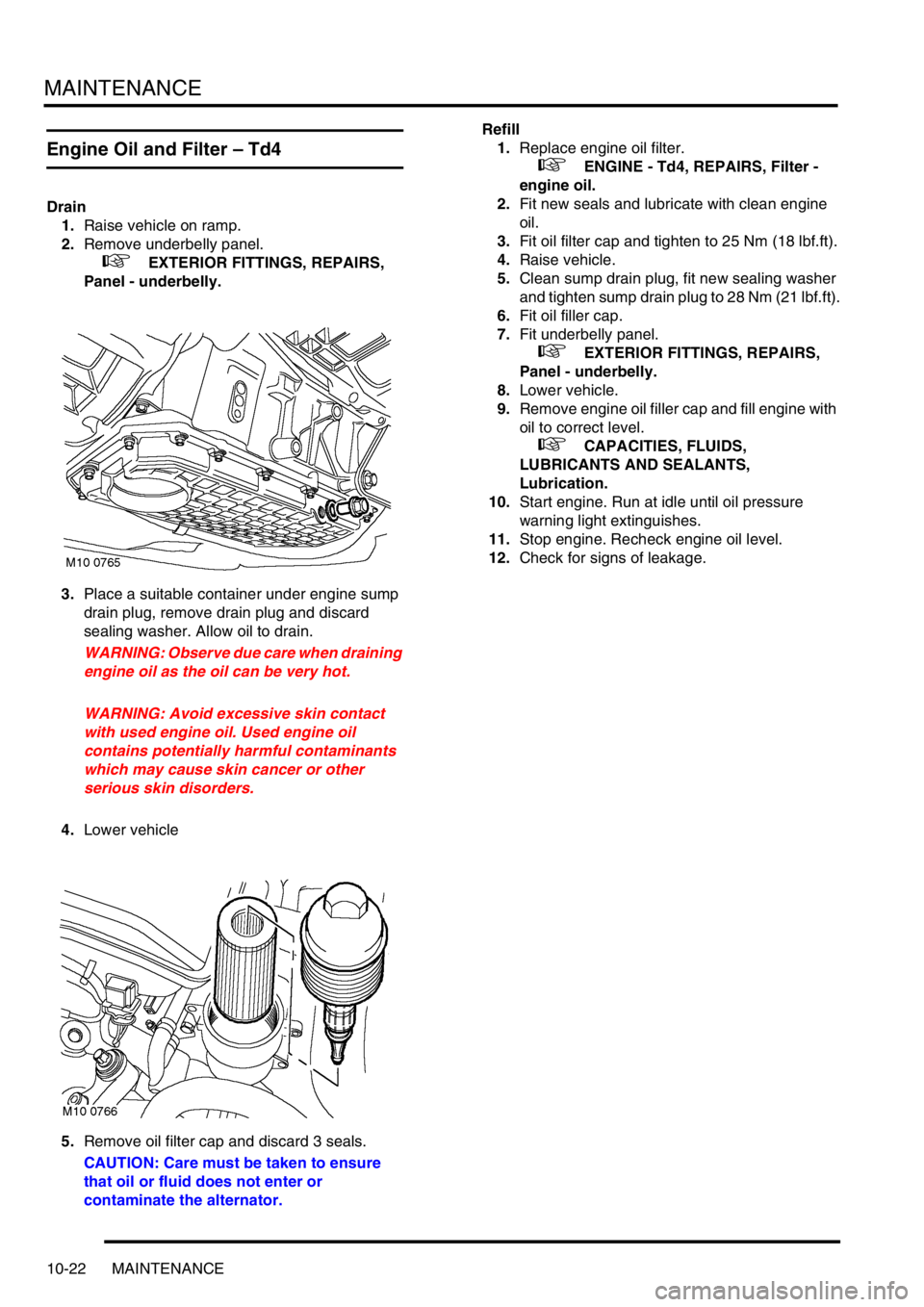
3.Place a suitable container under engine sump
drain plug, remove drain plug and discard
sealing washer. Allow oil to drain.
WARNING: Observe due care when draining
engine oil as the oil can be very hot.
WARNING: Avoid excessive skin contact
with used engine oil. Used engine oil
contains potentially harmful contaminants
which may cause skin cancer or other
serious skin disorders.
4.Lower vehicle
5.Remove oil filter cap and discard 3 seals.
CAUTION: Care must be taken to ensure
that oil or fluid does not enter or
contaminate the alternator.Refill
1.Replace engine oil filter.
+ ENGINE - Td4, REPAIRS, Filter -
engine oil.
2.Fit new seals and lubricate with clean engine
oil.
3.Fit oil filter cap and tighten to 25 Nm (18 lbf.ft).
4.Raise vehicle.
5.Clean sump drain plug, fit new sealing washer
and tighten sump drain plug to 28 Nm (21 lbf.ft).
6.Fit oil filler cap.
7.Fit underbelly panel.
+ EXTERIOR FITTINGS, REPAIRS,
Panel - underbelly.
8.Lower vehicle.
9.Remove engine oil filler cap and fill engine with
oil to correct level.
+ CAPACITIES, FLUIDS,
LUBRICANTS AND SEALANTS,
Lubrication.
10.Start engine. Run at idle until oil pressure
warning light extinguishes.
11.Stop engine. Recheck engine oil level.
12.Check for signs of leakage.
Page 170 of 1007
MAINTENANCE
MAINTENANCE 10-23
Engine Oil and Filter – K1.8
Drain
1.Raise vehicle on ramp.
2.Remove underbelly panel.
+ EXTERIOR FITTINGS, REPAIRS,
Panel - underbelly.
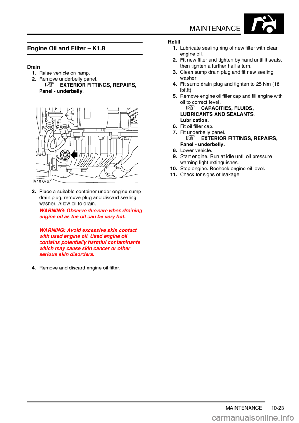
3.Place a suitable container under engine sump
drain plug, remove plug and discard sealing
washer. Allow oil to drain.
WARNING: Observe due care when draining
engine oil as the oil can be very hot.
WARNING: Avoid excessive skin contact
with used engine oil. Used engine oil
contains potentially harmful contaminants
which may cause skin cancer or other
serious skin disorders.
4.Remove and discard engine oil filter.Refill
1.Lubricate sealing ring of new filter with clean
engine oil.
2.Fit new filter and tighten by hand until it seats,
then tighten a further half a turn.
3.Clean sump drain plug and fit new sealing
washer.
4.Fit sump drain plug and tighten to 25 Nm (18
lbf.ft).
5.Remove engine oil filler cap and fill engine with
oil to correct level.
+ CAPACITIES, FLUIDS,
LUBRICANTS AND SEALANTS,
Lubrication.
6.Fit oil filler cap.
7.Fit underbelly panel.
+ EXTERIOR FITTINGS, REPAIRS,
Panel - underbelly.
8.Lower vehicle.
9.Start engine. Run at idle until oil pressure
warning light extinguishes.
10.Stop engine. Recheck engine oil level.
11.Check for signs of leakage.