LAND ROVER FREELANDER 2001 Workshop Manual
Manufacturer: LAND ROVER, Model Year: 2001, Model line: FREELANDER, Model: LAND ROVER FREELANDER 2001Pages: 1007, PDF Size: 23.47 MB
Page 421 of 1007
INTERMEDIATE REDUCTION DRIVE
41-18 REPAIRS
Gasket - end cover - IRD housing - K1.8
$% 41.27.05
Remove
1.Drain fluid from IRD.
+ INTERMEDIATE REDUCTION
DRIVE, ADJUSTMENTS, Intermediate
reduction drive (IRD) fluid - drain & refill -
Non NAS.
2.Remove drive shaft RH seal.
+ INTERMEDIATE REDUCTION
DRIVE, REPAIRS, Seal - driveshaft - RH.
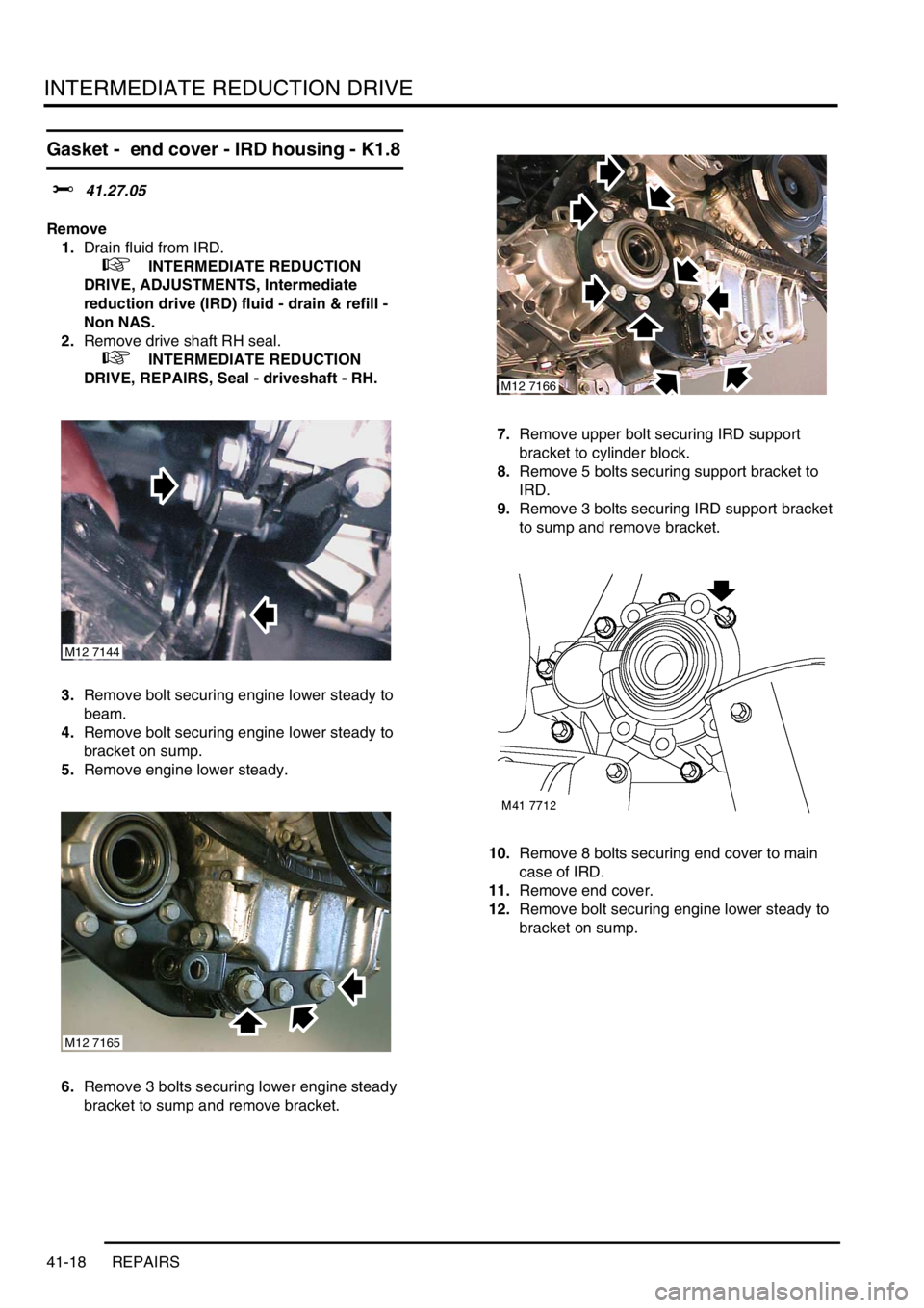
3.Remove bolt securing engine lower steady to
beam.
4.Remove bolt securing engine lower steady to
bracket on sump.
5.Remove engine lower steady.
6.Remove 3 bolts securing lower engine steady
bracket to sump and remove bracket.7.Remove upper bolt securing IRD support
bracket to cylinder block.
8.Remove 5 bolts securing support bracket to
IRD.
9.Remove 3 bolts securing IRD support bracket
to sump and remove bracket.
10.Remove 8 bolts securing end cover to main
case of IRD.
11.Remove end cover.
12.Remove bolt securing engine lower steady to
bracket on sump.
M12 7144
M12 7165
M12 7166
Page 422 of 1007
INTERMEDIATE REDUCTION DRIVE
REPAIRS 41-19
Refit
1.Clean remains of old sealant from mating faces
of end cover and IRD main case.
2.Apply a narrow bead of sealant, Part No. STC
4600to mating face of end cover.
3.Fit end cover to IRD and tighten bolts
progressively to 30 Nm (22 lbf.ft).
4.Fit IRD support bracket and tighten bolts
sufficiently only to pull mating faces together.
5.Final tighten bolts securing IRD support bracket
in following sequence:
l5 bolts securing IRD support bracket to IRD
50 Nm (37 lbf.ft),
l1 bolt securing support bracket to cylinder
block 45 Nm (33 lbf.ft),
l3 bolts securing support bracket to sump 88
Nm (65 lbf.ft).
6.Position engine lower steady bracket to sump,
fit and tighten bolts to 100 Nm (74 lbf.ft).
7.Fit engine lower steady, fit bolts and tighten to
80 Nm (59 lbf.ft).
8.
9.Fit drive shaft RH seal.
+ INTERMEDIATE REDUCTION
DRIVE, REPAIRS, Seal - driveshaft - RH.
10.Fill IRD to correct level with fluid.
+ INTERMEDIATE REDUCTION
DRIVE, ADJUSTMENTS, Intermediate
reduction drive (IRD) fluid - drain & refill -
Non NAS.
Seals - primary gear shaft
$% 41.29.02
Remove
1.Remove IRD.
+ INTERMEDIATE REDUCTION
DRIVE, REPAIRS, Intermediate reduction
drive (IRD) unit - K1.8.
+ INTERMEDIATE REDUCTION
DRIVE, REPAIRS, Intermediate reduction
drive (IRD) unit - Td4.
+ INTERMEDIATE REDUCTION
DRIVE, REPAIRS, Intermediate reduction
drive (IRD) unit - KV6.
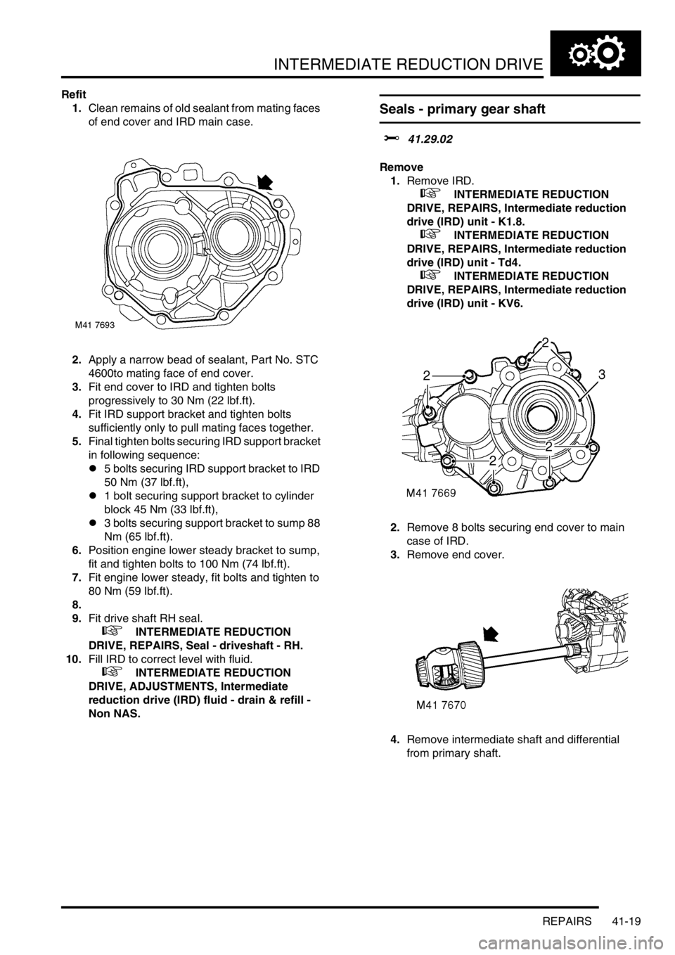
2.Remove 8 bolts securing end cover to main
case of IRD.
3.Remove end cover.
4.Remove intermediate shaft and differential
from primary shaft.
Page 423 of 1007
INTERMEDIATE REDUCTION DRIVE
41-20 REPAIRS
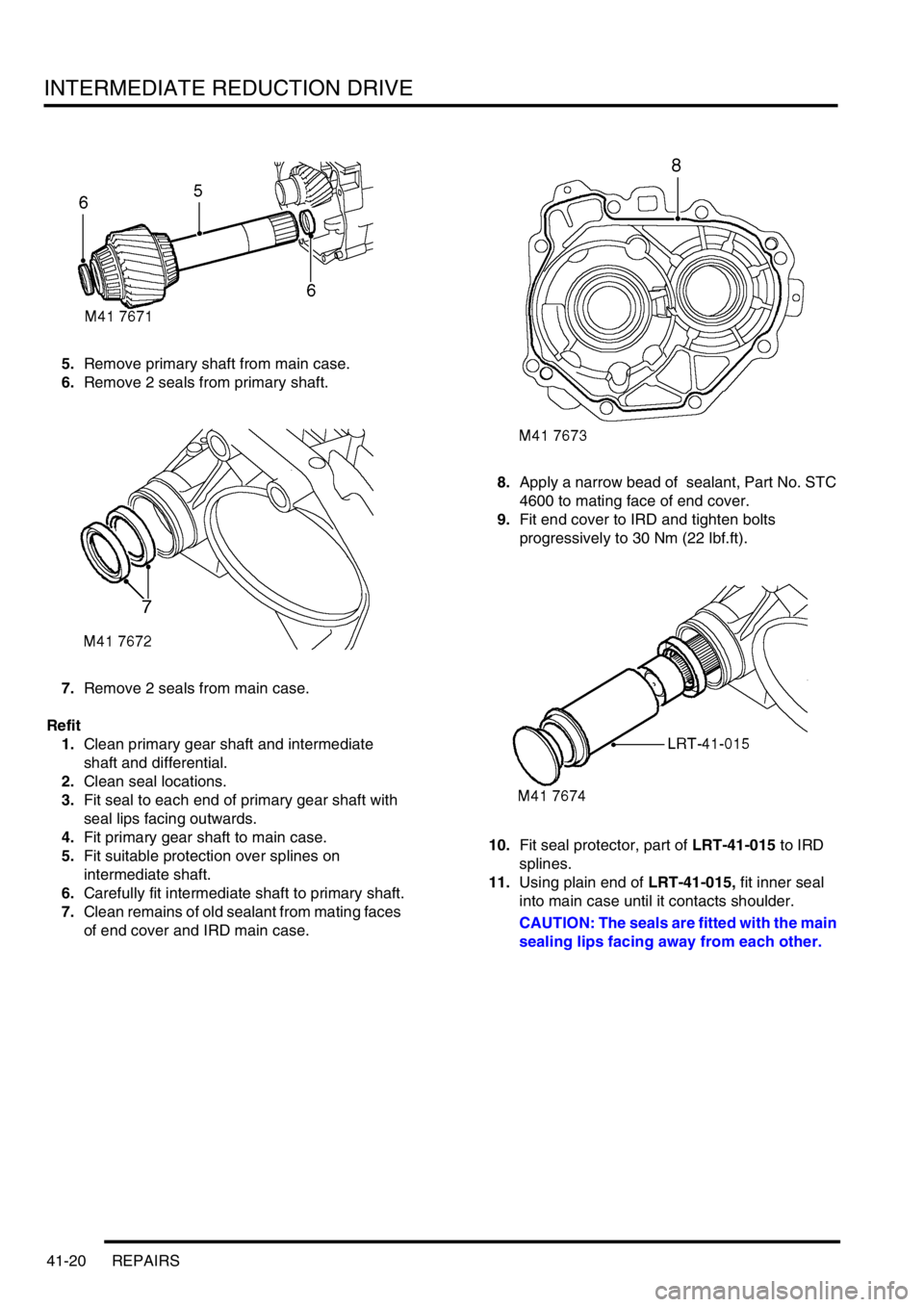
5.Remove primary shaft from main case.
6.Remove 2 seals from primary shaft.
7.Remove 2 seals from main case.
Refit
1.Clean primary gear shaft and intermediate
shaft and differential.
2.Clean seal locations.
3.Fit seal to each end of primary gear shaft with
seal lips facing outwards.
4.Fit primary gear shaft to main case.
5.Fit suitable protection over splines on
intermediate shaft.
6.Carefully fit intermediate shaft to primary shaft.
7.Clean remains of old sealant from mating faces
of end cover and IRD main case.8.Apply a narrow bead of sealant, Part No. STC
4600 to mating face of end cover.
9.Fit end cover to IRD and tighten bolts
progressively to 30 Nm (22 lbf.ft).
10.Fit seal protector, part of LRT-41-015 to IRD
splines.
11.Using plain end of LRT-41-015, fit inner seal
into main case until it contacts shoulder.
CAUTION: The seals are fitted with the main
sealing lips facing away from each other.
Page 424 of 1007
INTERMEDIATE REDUCTION DRIVE
REPAIRS 41-21
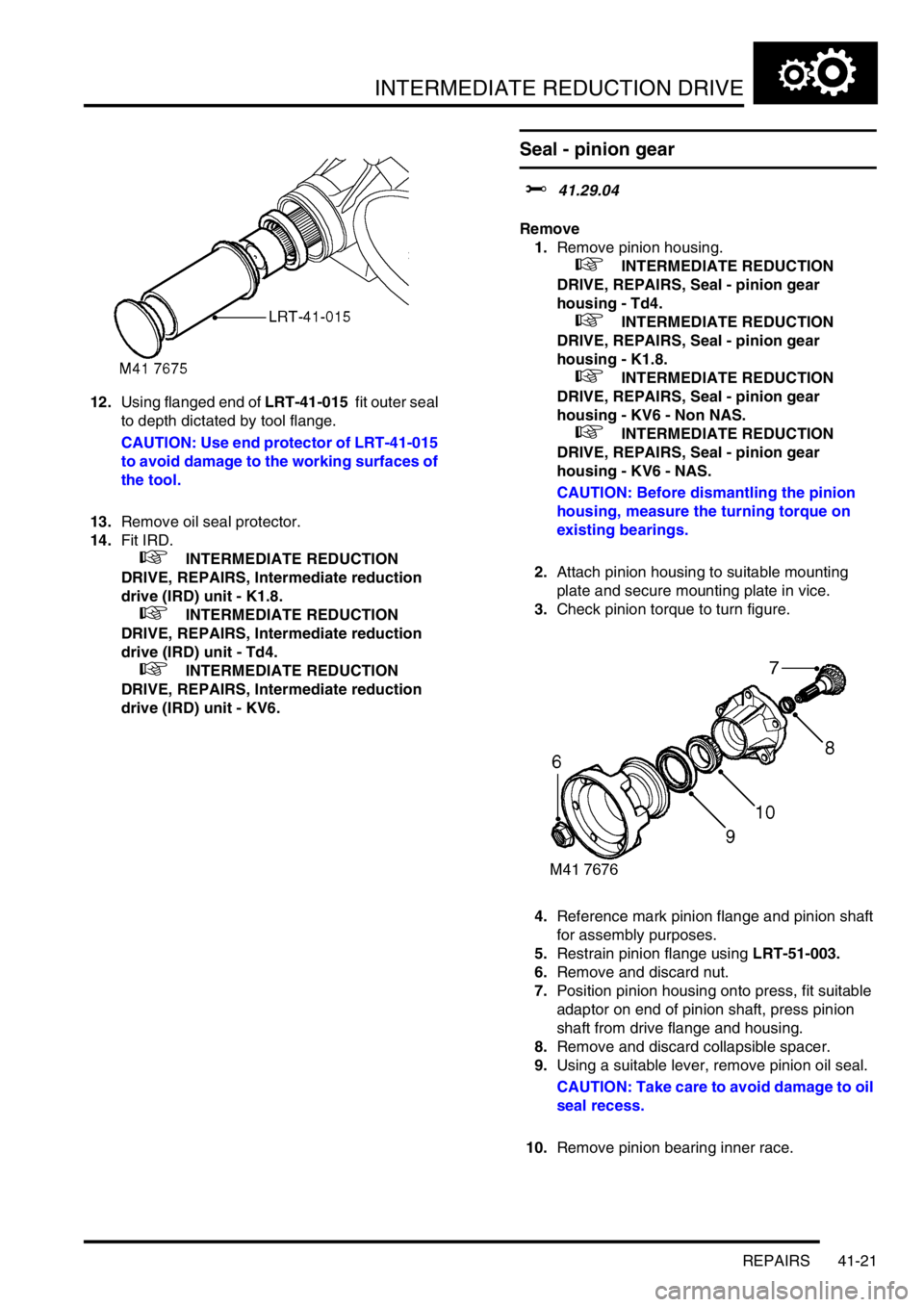
12.Using flanged end of LRT-41-015 fit outer seal
to depth dictated by tool flange.
CAUTION: Use end protector of LRT-41-015
to avoid damage to the working surfaces of
the tool.
13.Remove oil seal protector.
14.Fit IRD.
+ INTERMEDIATE REDUCTION
DRIVE, REPAIRS, Intermediate reduction
drive (IRD) unit - K1.8.
+ INTERMEDIATE REDUCTION
DRIVE, REPAIRS, Intermediate reduction
drive (IRD) unit - Td4.
+ INTERMEDIATE REDUCTION
DRIVE, REPAIRS, Intermediate reduction
drive (IRD) unit - KV6.
Seal - pinion gear
$% 41.29.04
Remove
1.Remove pinion housing.
+ INTERMEDIATE REDUCTION
DRIVE, REPAIRS, Seal - pinion gear
housing - Td4.
+ INTERMEDIATE REDUCTION
DRIVE, REPAIRS, Seal - pinion gear
housing - K1.8.
+ INTERMEDIATE REDUCTION
DRIVE, REPAIRS, Seal - pinion gear
housing - KV6 - Non NAS.
+ INTERMEDIATE REDUCTION
DRIVE, REPAIRS, Seal - pinion gear
housing - KV6 - NAS.
CAUTION: Before dismantling the pinion
housing, measure the turning torque on
existing bearings.
2.Attach pinion housing to suitable mounting
plate and secure mounting plate in vice.
3.Check pinion torque to turn figure.
4.Reference mark pinion flange and pinion shaft
for assembly purposes.
5.Restrain pinion flange using LRT-51-003.
6.Remove and discard nut.
7.Position pinion housing onto press, fit suitable
adaptor on end of pinion shaft, press pinion
shaft from drive flange and housing.
8.Remove and discard collapsible spacer.
9.Using a suitable lever, remove pinion oil seal.
CAUTION: Take care to avoid damage to oil
seal recess.
10.Remove pinion bearing inner race.
Page 425 of 1007
INTERMEDIATE REDUCTION DRIVE
41-22 REPAIRS
Refit
1.Clean pinion shaft, drive flange and housing.
2.Clean oil seal recess.
3.Lubricate and fit bearing to pinion housing.
4.Lubricate new seal.
5.Using a suitable adapter, press seal into
housing.
CAUTION: Oil seal must be flush with end of
pinion housing.
6.Assemble pinion to housing using new
collapsible spacer.
7.Lightly lubricate drive flange splines with
Molybdenum Disulphide grease.
8.Align pinion to drive flange reference marks
and press flange onto pinion shaft until a 2 mm
clearance exists in bearings.
9.Fit pinion assembly to mounting plate and
secure in vice.
10.Fit new pinion nut, hold pinion drive flange
using LRT-51-003 and tighten pinion nut to 150
Nm (111 lbf.ft).
11.Check pinion torque to turn figure.
NOTE: Figure for new bearings is 180 to 200
Ncm.
If original bearing figure is above 20 to 30 Ncm
and below new bearing figure, set to figure
recorded.
If original bearing is below 20 Ncm set to 20 to
30 Ncm.12.If turning torque is too low, carefully tighten nut
and recheck reading. If turning torque is too
high, pinion assembly will have to be
dismantled and a new collapsible spacer fitted.
Reassemble using new nut and recheck turning
torque.
13.Check drive flange run-out using a Dial Test
Indicator (DTI).
CAUTION: The drive flange run-out should
not exceed 0.05 mm.
14.Remove pinion housing from vice and
mounting plate.
15.Fit pinion housing.
+ INTERMEDIATE REDUCTION
DRIVE, REPAIRS, Seal - pinion gear
housing - Td4.
+ INTERMEDIATE REDUCTION
DRIVE, REPAIRS, Seal - pinion gear
housing - K1.8.
+ INTERMEDIATE REDUCTION
DRIVE, REPAIRS, Seal - pinion gear
housing - KV6 - Non NAS.
+ INTERMEDIATE REDUCTION
DRIVE, REPAIRS, Seal - pinion gear
housing - KV6 - NAS.
Page 426 of 1007
INTERMEDIATE REDUCTION DRIVE
REPAIRS 41-23
Seal - driveshaft - LH - Td4 & KV6 models
$% 41.29.08
Remove
1.Remove LH drive shaft.
+ DRIVESHAFTS, REPAIRS, Shaft
with both joints - LH.
2.Carefully remove and discard oil seal, take care
not to damage oil seal recess.
Refit
1.Clean oil seal recess.
CAUTION: Oil seal is waxed on outer
diameter and must not be lubricated before
fitting.
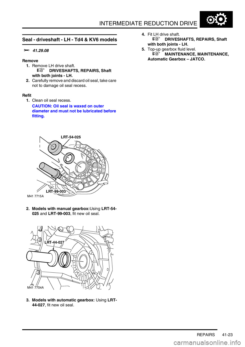
2. Models with manual gearbox:Using LRT-54-
025 and LRT-99-003, fit new oil seal.
3. Models with automatic gearbox: Using LRT-
44-027, fit new oil seal.4.Fit LH drive shaft.
+ DRIVESHAFTS, REPAIRS, Shaft
with both joints - LH.
5.Top-up gearbox fluid level.
+ MAINTENANCE, MAINTENANCE,
Automatic Gearbox – JATCO.
Page 427 of 1007
INTERMEDIATE REDUCTION DRIVE
41-24 REPAIRS
Seal - drive shaft - LH - K1.8
$% 41.29.08
Remove
1.Remove LH drive shaft.
+ DRIVESHAFTS, REPAIRS, Shaft
with both joints - LH.
2.Carefully remove oil seal from differential
housing, discard oil seal.
Refit
1.Thoroughly clean oil seal recess in differential
housing, splines and oil seal running surface on
drive shaft.
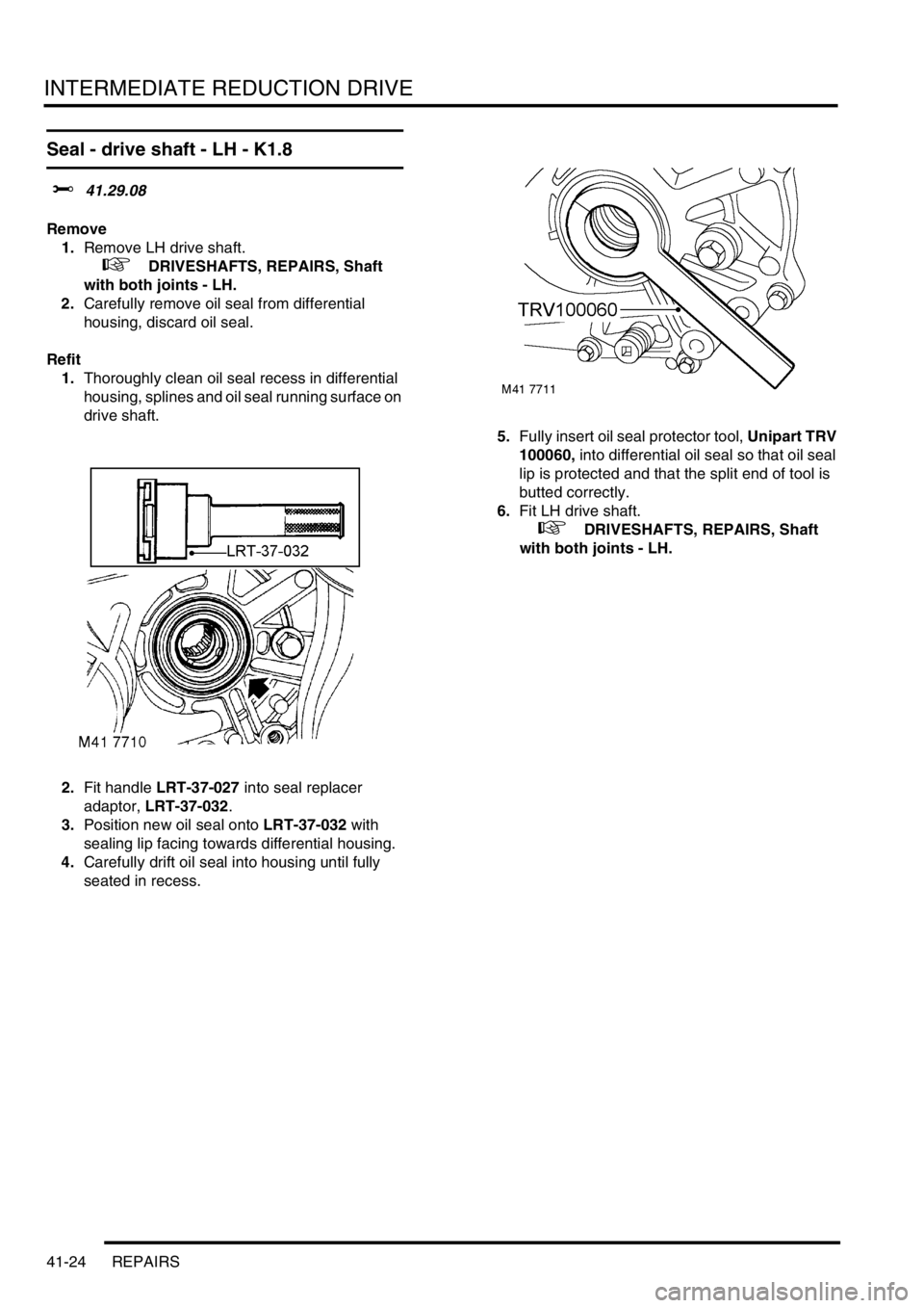
2.Fit handle LRT-37-027 into seal replacer
adaptor, LRT-37-032.
3.Position new oil seal onto LRT-37-032 with
sealing lip facing towards differential housing.
4.Carefully drift oil seal into housing until fully
seated in recess.5.Fully insert oil seal protector tool, Unipart TRV
100060, into differential oil seal so that oil seal
lip is protected and that the split end of tool is
butted correctly.
6.Fit LH drive shaft.
+ DRIVESHAFTS, REPAIRS, Shaft
with both joints - LH.
Page 428 of 1007
INTERMEDIATE REDUCTION DRIVE
REPAIRS 41-25
Seal - driveshaft - RH
$% 41.29.09
Remove
1.Remove RH drive shaft.
+ DRIVESHAFTS, REPAIRS, Shaft
with both joints - RH.
2.Carefully remove and discard oil seal, take care
not to damage oil seal recess.
Refit
1.Clean oil seal recess.
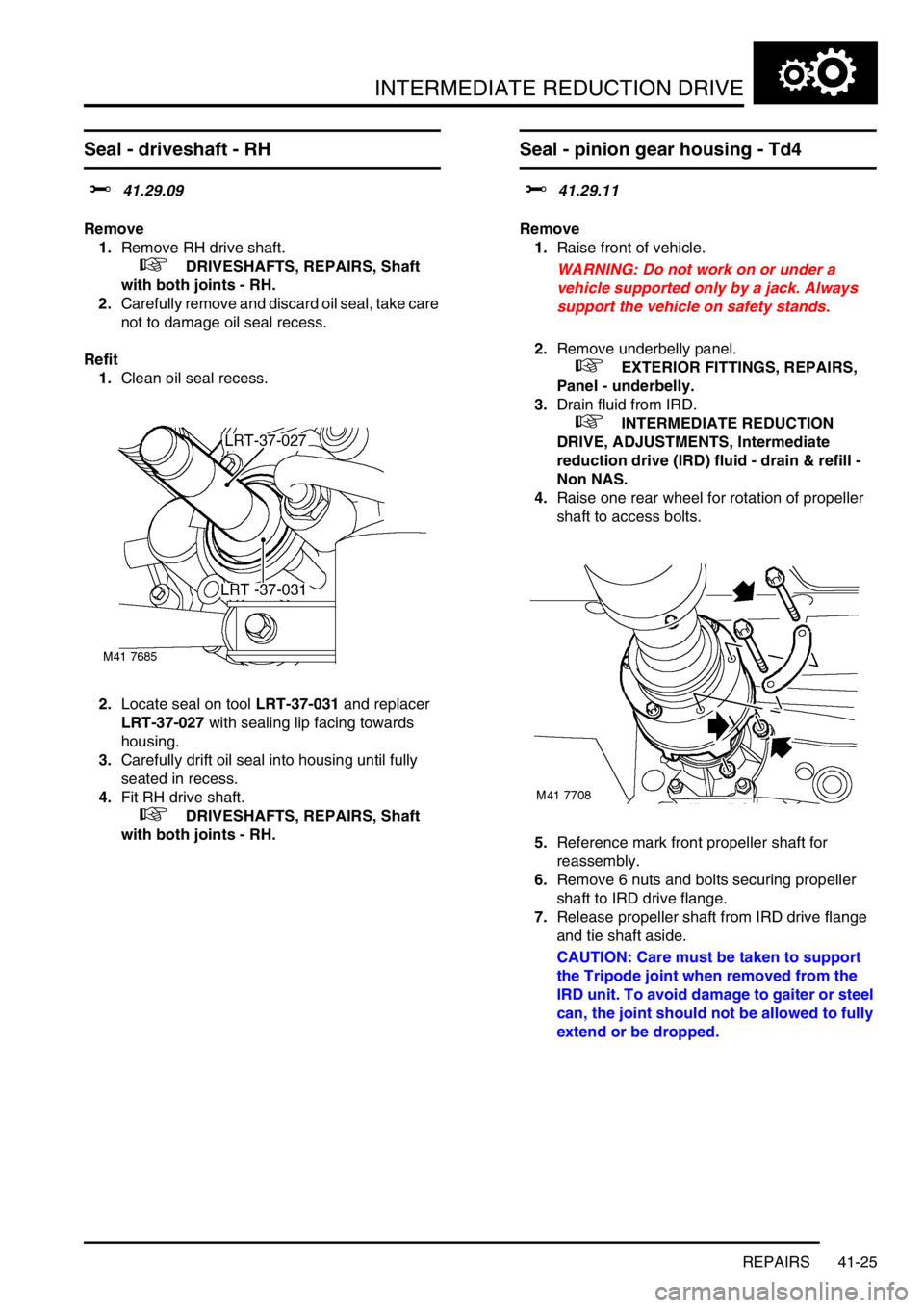
2.Locate seal on tool LRT-37-031 and replacer
LRT-37-027 with sealing lip facing towards
housing.
3.Carefully drift oil seal into housing until fully
seated in recess.
4.Fit RH drive shaft.
+ DRIVESHAFTS, REPAIRS, Shaft
with both joints - RH.
Seal - pinion gear housing - Td4
$% 41.29.11
Remove
1.Raise front of vehicle.
WARNING: Do not work on or under a
vehicle supported only by a jack. Always
support the vehicle on safety stands.
2.Remove underbelly panel.
+ EXTERIOR FITTINGS, REPAIRS,
Panel - underbelly.
3.Drain fluid from IRD.
+ INTERMEDIATE REDUCTION
DRIVE, ADJUSTMENTS, Intermediate
reduction drive (IRD) fluid - drain & refill -
Non NAS.
4.Raise one rear wheel for rotation of propeller
shaft to access bolts.
5.Reference mark front propeller shaft for
reassembly.
6.Remove 6 nuts and bolts securing propeller
shaft to IRD drive flange.
7.Release propeller shaft from IRD drive flange
and tie shaft aside.
CAUTION: Care must be taken to support
the Tripode joint when removed from the
IRD unit. To avoid damage to gaiter or steel
can, the joint should not be allowed to fully
extend or be dropped.
Page 429 of 1007
INTERMEDIATE REDUCTION DRIVE
41-26 REPAIRS
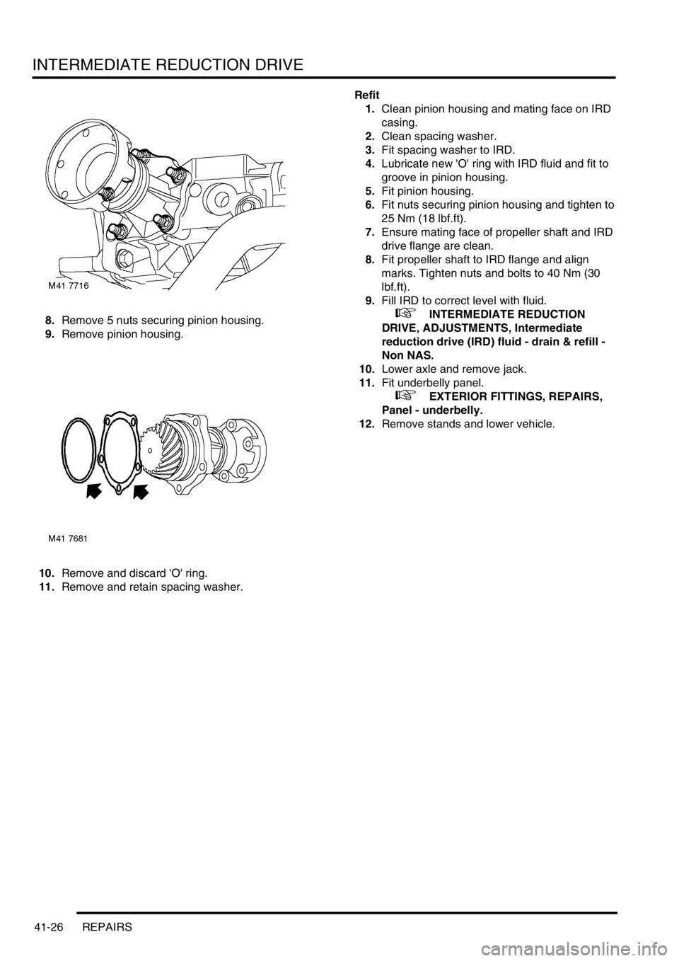
8.Remove 5 nuts securing pinion housing.
9.Remove pinion housing.
10.Remove and discard 'O' ring.
11.Remove and retain spacing washer.Refit
1.Clean pinion housing and mating face on IRD
casing.
2.Clean spacing washer.
3.Fit spacing washer to IRD.
4.Lubricate new 'O' ring with IRD fluid and fit to
groove in pinion housing.
5.Fit pinion housing.
6.Fit nuts securing pinion housing and tighten to
25 Nm (18 lbf.ft).
7.Ensure mating face of propeller shaft and IRD
drive flange are clean.
8.Fit propeller shaft to IRD flange and align
marks. Tighten nuts and bolts to 40 Nm (30
lbf.ft).
9.Fill IRD to correct level with fluid.
+ INTERMEDIATE REDUCTION
DRIVE, ADJUSTMENTS, Intermediate
reduction drive (IRD) fluid - drain & refill -
Non NAS.
10.Lower axle and remove jack.
11.Fit underbelly panel.
+ EXTERIOR FITTINGS, REPAIRS,
Panel - underbelly.
12.Remove stands and lower vehicle.
Page 430 of 1007
INTERMEDIATE REDUCTION DRIVE
REPAIRS 41-27
Seal - pinion gear housing - K1.8
$% 41.29.11
Remove
1.Remove underbelly panel.
+ EXTERIOR FITTINGS, REPAIRS,
Panel - underbelly.
2.Drain fluid from IRD.
+ INTERMEDIATE REDUCTION
DRIVE, ADJUSTMENTS, Intermediate
reduction drive (IRD) fluid - drain & refill -
Non NAS.
3.Raise one rear wheel for rotation of propeller
shaft to access bolts.
4.Reference mark front propeller shaft for
reassembly.
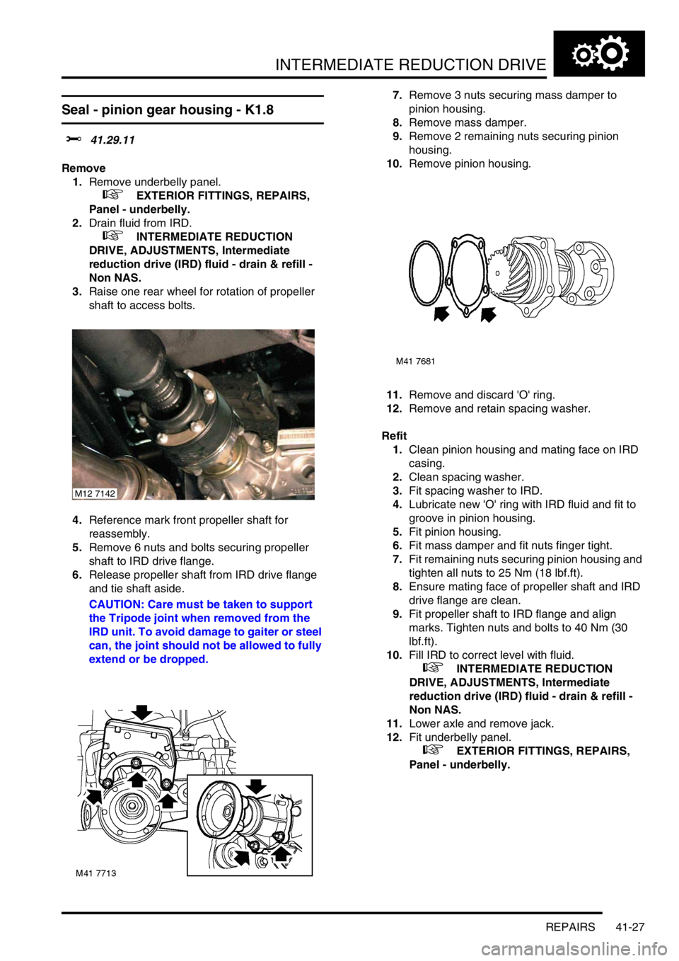
5.Remove 6 nuts and bolts securing propeller
shaft to IRD drive flange.
6.Release propeller shaft from IRD drive flange
and tie shaft aside.
CAUTION: Care must be taken to support
the Tripode joint when removed from the
IRD unit. To avoid damage to gaiter or steel
can, the joint should not be allowed to fully
extend or be dropped.7.Remove 3 nuts securing mass damper to
pinion housing.
8.Remove mass damper.
9.Remove 2 remaining nuts securing pinion
housing.
10.Remove pinion housing.
11.Remove and discard 'O' ring.
12.Remove and retain spacing washer.
Refit
1.Clean pinion housing and mating face on IRD
casing.
2.Clean spacing washer.
3.Fit spacing washer to IRD.
4.Lubricate new 'O' ring with IRD fluid and fit to
groove in pinion housing.
5.Fit pinion housing.
6.Fit mass damper and fit nuts finger tight.
7.Fit remaining nuts securing pinion housing and
tighten all nuts to 25 Nm (18 lbf.ft).
8.Ensure mating face of propeller shaft and IRD
drive flange are clean.
9.Fit propeller shaft to IRD flange and align
marks. Tighten nuts and bolts to 40 Nm (30
lbf.ft).
10.Fill IRD to correct level with fluid.
+ INTERMEDIATE REDUCTION
DRIVE, ADJUSTMENTS, Intermediate
reduction drive (IRD) fluid - drain & refill -
Non NAS.
11.Lower axle and remove jack.
12.Fit underbelly panel.
+ EXTERIOR FITTINGS, REPAIRS,
Panel - underbelly.
M12 7142