check engine LAND ROVER FREELANDER 2001 Repair Manual
[x] Cancel search | Manufacturer: LAND ROVER, Model Year: 2001, Model line: FREELANDER, Model: LAND ROVER FREELANDER 2001Pages: 1007, PDF Size: 23.47 MB
Page 366 of 1007
COOLING SYSTEM - K SERIES KV6
ADJUSTMENTS 26-3-1
COOLING SYS TEM - K SER IES KV6 ADJUST ME NTS
Coolant - drain and refill
$% 26.10.01
Drain
1.Remove engine acoustic cover.
+ ENGINE - K SERIES KV6, REPAIRS,
Cover - engine acoustic.
2.Visually check engine and cooling system for
signs of coolant leaks.
WARNING: Since injury such as scalding
could be caused by escaping steam or
coolant, do not remove the filler cap from
the coolant expansion tank while the
system is hot.
3.Examine hoses for signs of cracking, distortion
and security of connections.
4.Remove expansion tank filler cap.
5.Remove underbelly panel.
+ EXTERIOR FITTINGS, REPAIRS,
Panel - underbelly.
6.Position container to collect coolant.
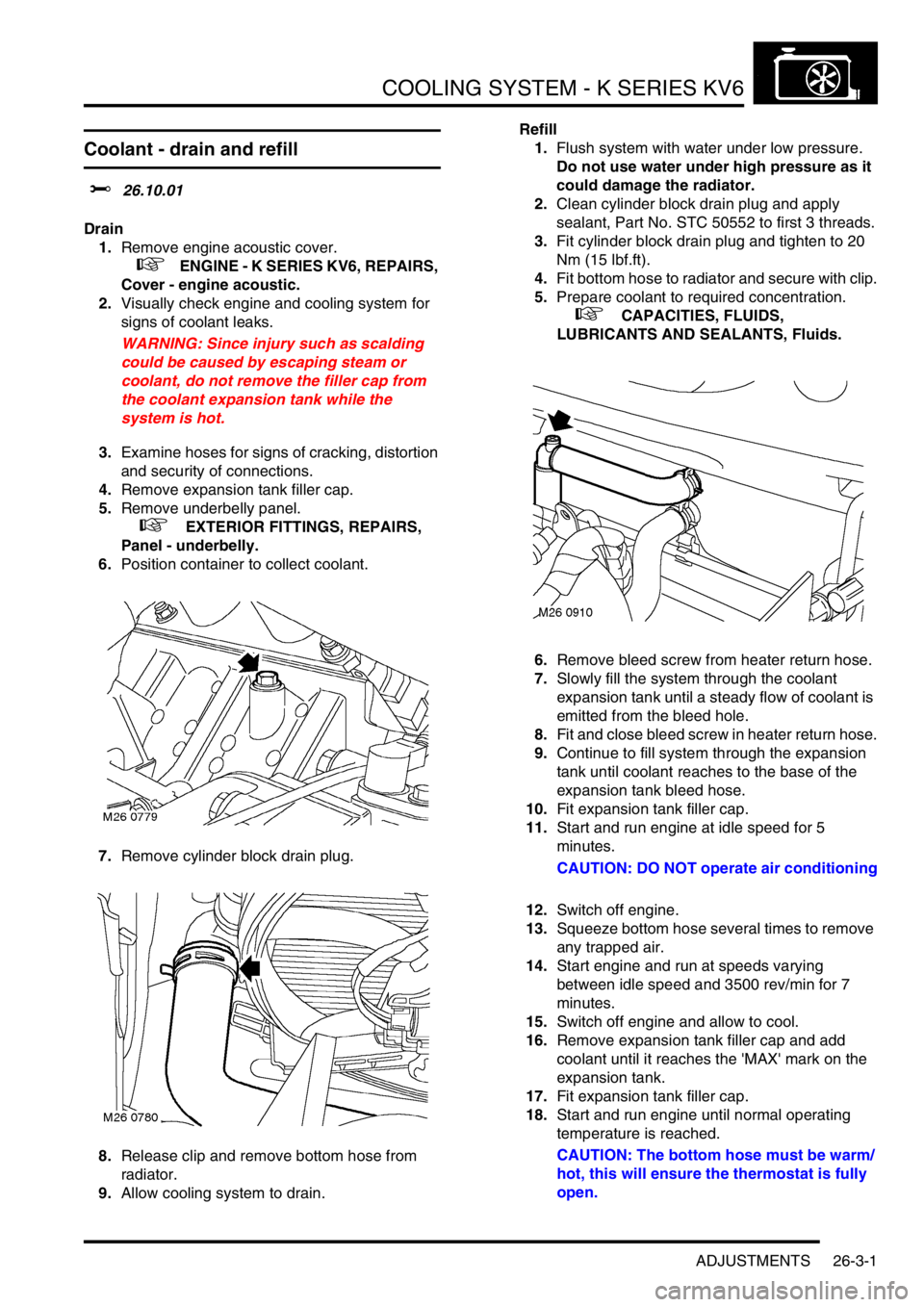
7.Remove cylinder block drain plug.
8.Release clip and remove bottom hose from
radiator.
9.Allow cooling system to drain.Refill
1.Flush system with water under low pressure.
Do not use water under high pressure as it
could damage the radiator.
2.Clean cylinder block drain plug and apply
sealant, Part No. STC 50552 to first 3 threads.
3.Fit cylinder block drain plug and tighten to 20
Nm (15 lbf.ft).
4.Fit bottom hose to radiator and secure with clip.
5.Prepare coolant to required concentration.
+ CAPACITIES, FLUIDS,
LUBRICANTS AND SEALANTS, Fluids.
6.Remove bleed screw from heater return hose.
7.Slowly fill the system through the coolant
expansion tank until a steady flow of coolant is
emitted from the bleed hole.
8.Fit and close bleed screw in heater return hose.
9.Continue to fill system through the expansion
tank until coolant reaches to the base of the
expansion tank bleed hose.
10.Fit expansion tank filler cap.
11.Start and run engine at idle speed for 5
minutes.
CAUTION: DO NOT operate air conditioning
12.Switch off engine.
13.Squeeze bottom hose several times to remove
any trapped air.
14.Start engine and run at speeds varying
between idle speed and 3500 rev/min for 7
minutes.
15.Switch off engine and allow to cool.
16.Remove expansion tank filler cap and add
coolant until it reaches the 'MAX' mark on the
expansion tank.
17.Fit expansion tank filler cap.
18.Start and run engine until normal operating
temperature is reached.
CAUTION: The bottom hose must be warm/
hot, this will ensure the thermostat is fully
open.
Page 367 of 1007

COOLING SYSTEM - K SERIES KV6
26-3-2 ADJUSTMENTS
19.Ensure warm air is available at vents.
NOTE: If warm air is not available, an air-lock
may be present in heater matrix. If necessary,
allow engine to cool, remove expansion tank
filler cap and repeat bleed operation at heater
hose
20.Switch off engine and allow to cool.
21.Check for leaks and top-up coolant to 'MAX'
mark on expansion tank
22.Fit underbelly panel.
+ EXTERIOR FITTINGS, REPAIRS,
Panel - underbelly.
23.Fit engine acoustic cover.
+ ENGINE - K SERIES KV6, REPAIRS,
Cover - engine acoustic.
Page 390 of 1007
MANIFOLDS & EXHAUST SYSTEMS - K SERIES KV6
REPAIRS 30-3-17
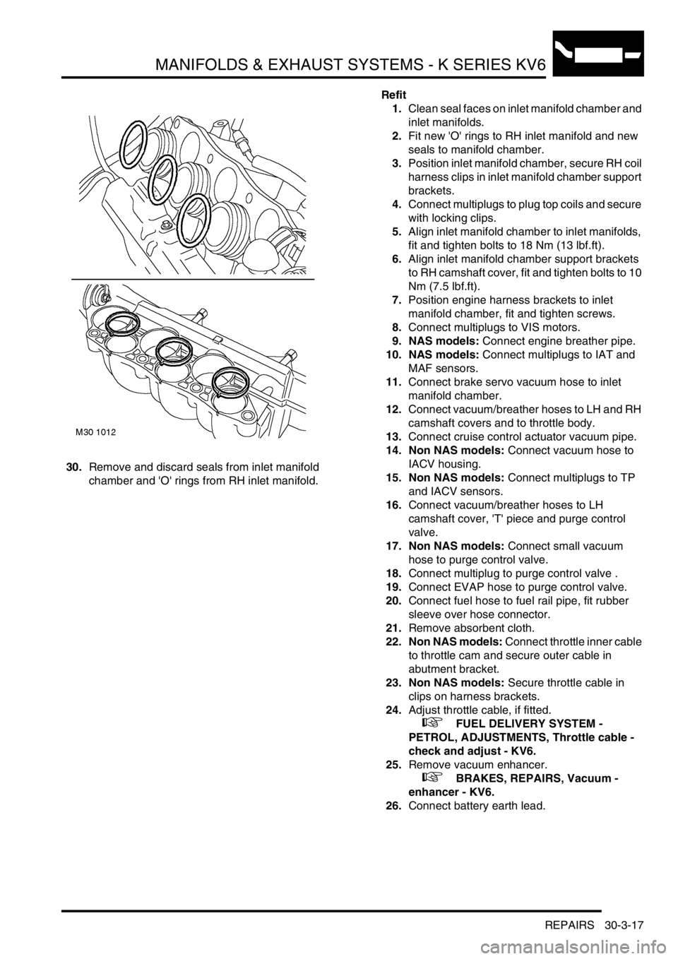
30.Remove and discard seals from inlet manifold
chamber and 'O' rings from RH inlet manifold.Refit
1.Clean seal faces on inlet manifold chamber and
inlet manifolds.
2.Fit new 'O' rings to RH inlet manifold and new
seals to manifold chamber.
3.Position inlet manifold chamber, secure RH coil
harness clips in inlet manifold chamber support
brackets.
4.Connect multiplugs to plug top coils and secure
with locking clips.
5.Align inlet manifold chamber to inlet manifolds,
fit and tighten bolts to 18 Nm (13 lbf.ft).
6.Align inlet manifold chamber support brackets
to RH camshaft cover, fit and tighten bolts to 10
Nm (7.5 lbf.ft).
7.Position engine harness brackets to inlet
manifold chamber, fit and tighten screws.
8.Connect multiplugs to VIS motors.
9. NAS models: Connect engine breather pipe.
10. NAS models: Connect multiplugs to IAT and
MAF sensors.
11.Connect brake servo vacuum hose to inlet
manifold chamber.
12.Connect vacuum/breather hoses to LH and RH
camshaft covers and to throttle body.
13.Connect cruise control actuator vacuum pipe.
14. Non NAS models: Connect vacuum hose to
IACV housing.
15. Non NAS models: Connect multiplugs to TP
and IACV sensors.
16.Connect vacuum/breather hoses to LH
camshaft cover, 'T' piece and purge control
valve.
17. Non NAS models: Connect small vacuum
hose to purge control valve.
18.Connect multiplug to purge control valve .
19.Connect EVAP hose to purge control valve.
20.Connect fuel hose to fuel rail pipe, fit rubber
sleeve over hose connector.
21.Remove absorbent cloth.
22. Non NAS models: Connect throttle inner cable
to throttle cam and secure outer cable in
abutment bracket.
23. Non NAS models: Secure throttle cable in
clips on harness brackets.
24.Adjust throttle cable, if fitted.
+ FUEL DELIVERY SYSTEM -
PETROL, ADJUSTMENTS, Throttle cable -
check and adjust - KV6.
25.Remove vacuum enhancer.
+ BRAKES, REPAIRS, Vacuum -
enhancer - KV6.
26.Connect battery earth lead.
Page 395 of 1007

MANIFOLDS & EXHAUST SYSTEMS - K SERIES KV6
30-3-22 REPAIRS
Refit
1.Clean seal faces on inlet manifold chamber and
inlet manifolds.
2.Fit new 'O' rings to RH inlet manifold and new
seals to inlet manifold chamber.
3.Position inlet manifold chamber, secure RH coil
harness clips in inlet manifold chamber support
brackets.
4.Align inlet manifold chamber to inlet manifolds,
fit and tighten bolts to 18 Nm (13 lbf.ft).
5.Align inlet manifold chamber support brackets
to RH camshaft cover, fit and tighten bolts to 10
Nm (7 lbf.ft).
6.Connect multiplugs to plug top coils and secure
with locking clips.
7.Position engine harness brackets to inlet
manifold chamber, fit and tighten screws.
8.Connect multiplugs to VIS motors.
9. NAS models: Align harness and fuel feed pipe.
Secure harness and pipe in clip on manifold
chamber.
10. NAS models: Using a new clip, fit intake hose
to throttle body and secure hose with clip.
11. NAS models: Connect multiplug to throttle
body.
12. NAS models: Connect multiplugs to IAT and
MAF sensors.
13. NAS models: Fit vacuum/breather pipe and
connect to LH camshaft cover, RH camshaft
cover link pipe and inlet manifold chamber.
14. NAS models: Using a new clip, fit vacuum/
breather pipe to engine air intake hose and
secure pipe with clip.
15. NAS models: Connect vacuum/breather pipe
to LH and RH camshaft covers. Fit pipe into
clip.16. Non NAS models: Connect cruise control
actuator vacuum pipe.
17. Non NAS models: Fit vacuum/breather pipe to
throttle body and connect pipe to LH and RH
camshaft covers.
18. Non NAS models: Fit vacuum/breather pipe to
purge control valve and LH camshaft cover.
Using a new clip, connect pipe to 'T' piece and
secure pipe with clip.
19. Non NAS models: Connect multiplug to TP
sensor.
20. Non NAS models: Connect multiplug to IACV.
21. Non NAS models: Connect vacuum pipe to
IACV.
22. Non NAS models: Connect small vacuum pipe
to purge control valve.
23.Connect multiplug to purge control valve .
24.Connect EVAP hose to purge control valve.
25.Connect fuel hose to fuel rail pipe, fit rubber
sleeve over hose connector.
26. Non NAS models: Connect throttle inner cable
to throttle cam and secure outer cable in
abutment bracket.
27. Non NAS models: Secure throttle cable in
clips on harness brackets.
28. Non NAS models: Adjust throttle cable.
+ FUEL DELIVERY SYSTEM -
PETROL, ADJUSTMENTS, Throttle cable -
check and adjust - KV6.
29.Fit vacuum enhancer.
+ BRAKES, REPAIRS, Vacuum -
enhancer - KV6.
30.Connect the battery earth lead.
Page 436 of 1007
AUTOMATIC GEARBOX - JATCO
ADJUSTMENTS 44-1
AUTOMATIC GE ARBOX - JATCO ADJUST ME NTS
Inhibitor switch - adjust
$% 44.15.18
Adjust
1.Set gear selector lever to 'N' position.
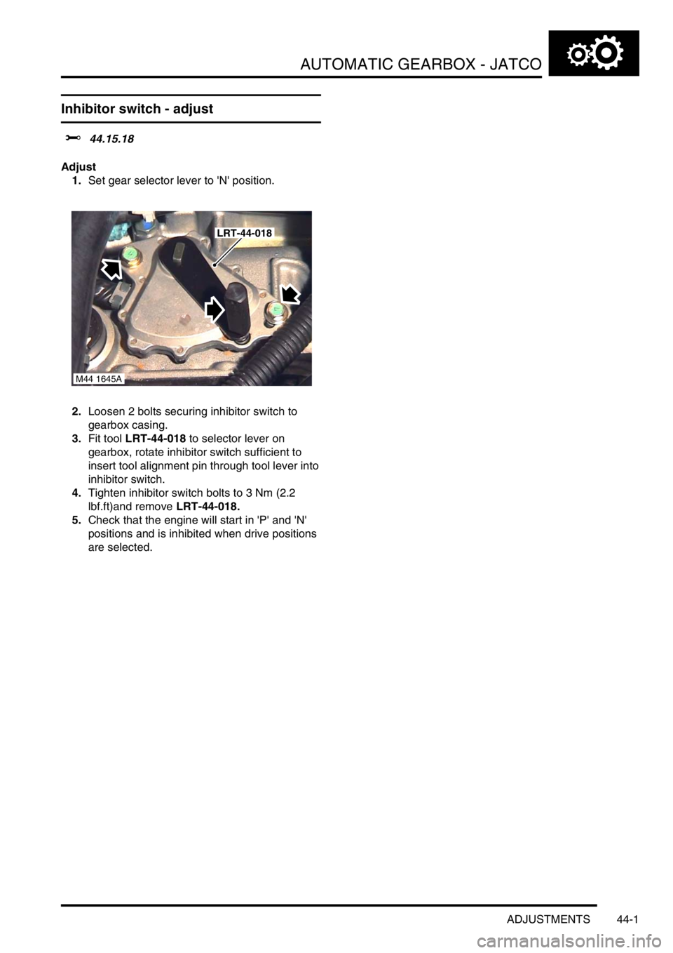
2.Loosen 2 bolts securing inhibitor switch to
gearbox casing.
3.Fit tool LRT-44-018 to selector lever on
gearbox, rotate inhibitor switch sufficient to
insert tool alignment pin through tool lever into
inhibitor switch.
4.Tighten inhibitor switch bolts to 3 Nm (2.2
lbf.ft)and remove LRT-44-018.
5.Check that the engine will start in 'P' and 'N'
positions and is inhibited when drive positions
are selected.
M44 1645A
LRT-44-018
Page 438 of 1007
AUTOMATIC GEARBOX - JATCO
ADJUSTMENTS 44-3
Selector cable - adjust
$% 44.30.04
Adjust
1.Remove underbelly panel.
+ EXTERIOR FITTINGS, REPAIRS,
Panel - underbelly.
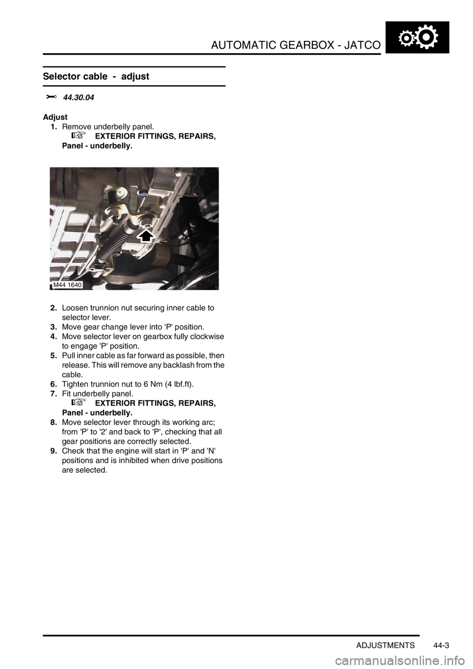
2.Loosen trunnion nut securing inner cable to
selector lever.
3.Move gear change lever into 'P' position.
4.Move selector lever on gearbox fully clockwise
to engage 'P' position.
5.Pull inner cable as far forward as possible, then
release. This will remove any backlash from the
cable.
6.Tighten trunnion nut to 6 Nm (4 lbf.ft).
7.Fit underbelly panel.
+ EXTERIOR FITTINGS, REPAIRS,
Panel - underbelly.
8.Move selector lever through its working arc;
from 'P' to '2' and back to 'P', checking that all
gear positions are correctly selected.
9.Check that the engine will start in 'P' and 'N'
positions and is inhibited when drive positions
are selected.
M44 1640
Page 451 of 1007

AUTOMATIC GEARBOX - JATCO
44-16 REPAIRS
35.Remove 2 top bolts securing gearbox to
engine.
36.Release gearbox from 2 dowels.
37.Remove gearbox assembly.
38.Fit converter retaining plate and secure with
bolts.Refit
1.Remove torque converter retaining plate.
2.Ensure converter is fully located in oil pump
drive by checking depth 'A' as illustrated. Depth
A = 4 mm.
3.Clean gearbox to engine mating faces, dowels
and dowel holes.
4.Fit gearbox assembly.
5.Fit bolts securing gearbox and tighten to 85 Nm
(63 lbf.ft).
6.Disconnect lifting equipment.
7.Clean CKP sensor and mating face.
8.Fit CKP sensor, fit bolt and tighten to 9 Nm (7
lbf.ft).
9.Position fluid cooler, tighten M12 bolts to 85 Nm
(63 lbf.ft) and M8 bolt to 25 Nm (18 lbf.ft).
10.Connect hoses to fluid cooler.
11.Clean fluid cooler unions.
12.Lubricate new 'O' rings with clean transmission
fluid and fit 'O' rings to fluid cooler hoses.
+ CAPACITIES, FLUIDS,
LUBRICANTS AND SEALANTS,
Lubrication.
13.Connect fluid cooler hoses to gearbox and
tighten unions to 18 Nm (13 lbf.ft).
14.Clean starter motor mating faces.
15.Position starter motor to gearbox, align CKP
sensor multiplug bracket, fit and tighten bolts to
45 Nm (33 lbf.ft).
16.Using gearbox bracket bolts, secure LRT-44-
026 lifting bracket to gearbox.
17.Position IRD cooling hose retainer, fit bolt and
tighten to 25 Nm (18 lbf.ft).
18.Align marks on drive plate to torque converter.
19.Fit bolts securing drive plate to torque converter
and tighten bolts to 45 Nm (33 lbf.ft).
20.Clean torque converter access plate.
M44 1689
A
M44 1668
Page 457 of 1007

AUTOMATIC GEARBOX - JATCO
44-22 REPAIRS
42.Remove 2 top bolts securing gearbox to
engine.
43.Release gearbox from 2 dowels.
44.Manoeuvre and lower gearbox to floor.
45.Fit converter retaining plate and secure with
bolts.Refit
1.Remove torque converter retaining plate.
2.Ensure converter is fully located in oil pump
drive by checking depth 'A' as illustrated. Depth
A = 4 mm.
3.Clean gearbox to engine mating faces, dowels
and dowel holes.
4.Fit gearbox assembly.
5.Fit bolts securing gearbox and tighten to 85 Nm
(63 lbf.ft).
6.Position LH mounting bracket to gearbox, fit
and tighten bolts to 85 Nm (63 lbf.ft).
7.Position LH mounting to body, fit and tighten
bolts to 48 Nm (35 lbf.ft).
8.Align gearbox bracket to LH body mounting, fit
and tighten through bolt to 100 Nm (74 lbf.ft).
9.Disconnect lifting equipment.
10.Remove nuts and bolts securing lifting brackets
to gearbox and remove brackets.
11.Connect engine and gearbox harness
multiplugs to main harness.
12.Secure multiplugs to clips.
13.Position engine earth lead and secure with bolt.
14.Fit starter motor.
+ CHARGING AND STARTING,
REPAIRS, Starter motor - KV6.
15.Clean throttle housing and manifold chamber
mating faces.
16.Fit new seal to inlet manifold chamber.
17.Position throttle housing to manifold chamber,
fit Torx screws and tighten to 7 Nm (7 lbf.ft).
18.Connect throttle inner cable to throttle cam and
secure outer cable in abutment bracket, if fitted.
19.Connect hose to cruise control actuator.
20.Secure breather hoses to throttle housing, if
fitted.
21.Adjust throttle cable, if fitted.
+ FUEL DELIVERY SYSTEM -
PETROL, ADJUSTMENTS, Throttle cable -
check and adjust - KV6.
22.Clean CKP sensor and mating face.
M44 1689
A
M44 1668
Page 461 of 1007
AUTOMATIC GEARBOX - JATCO
44-26 REPAIRS
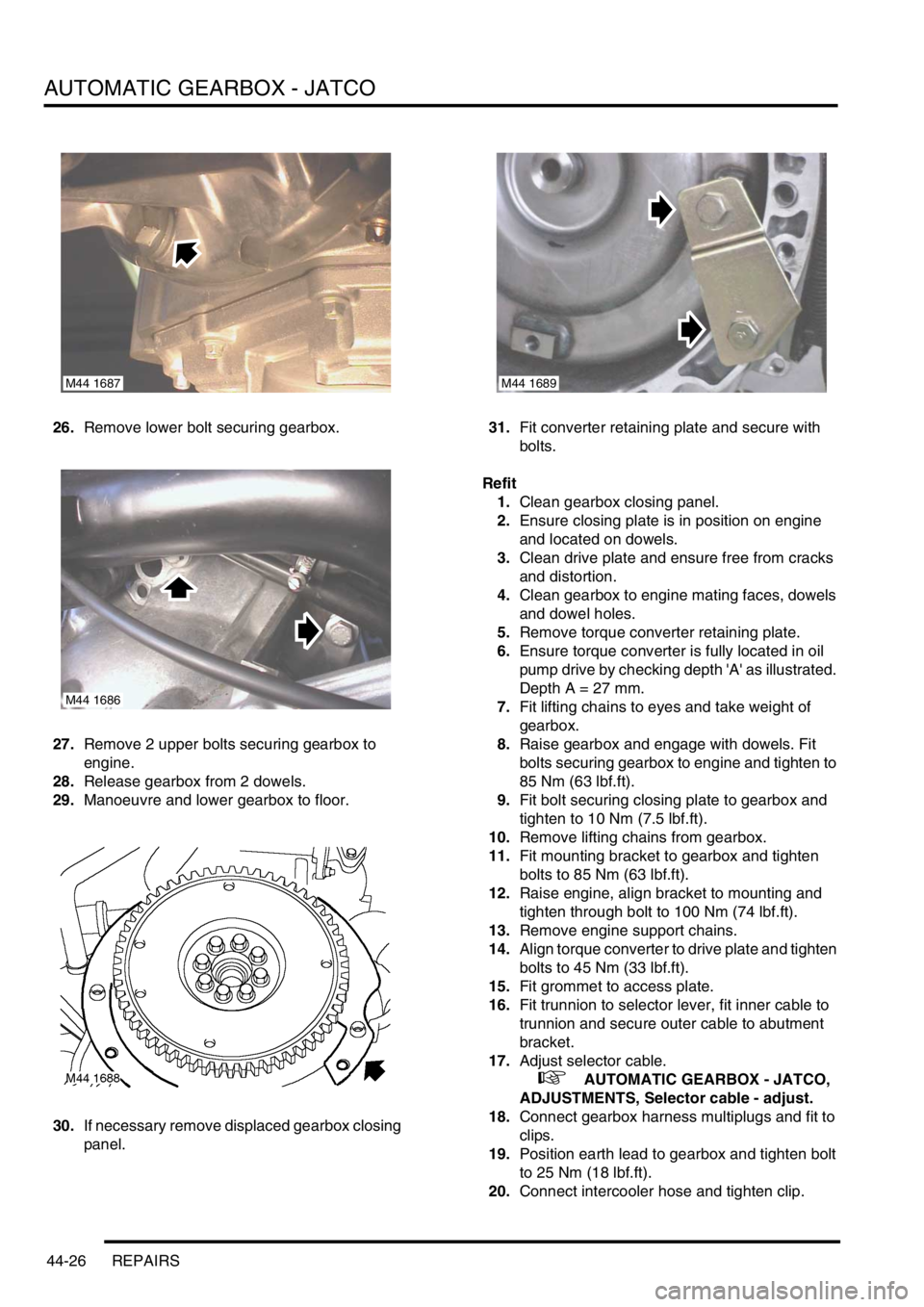
26.Remove lower bolt securing gearbox.
27.Remove 2 upper bolts securing gearbox to
engine.
28.Release gearbox from 2 dowels.
29.Manoeuvre and lower gearbox to floor.
30.If necessary remove displaced gearbox closing
panel.31.Fit converter retaining plate and secure with
bolts.
Refit
1.Clean gearbox closing panel.
2.Ensure closing plate is in position on engine
and located on dowels.
3.Clean drive plate and ensure free from cracks
and distortion.
4.Clean gearbox to engine mating faces, dowels
and dowel holes.
5.Remove torque converter retaining plate.
6.Ensure torque converter is fully located in oil
pump drive by checking depth 'A' as illustrated.
Depth A = 27 mm.
7.Fit lifting chains to eyes and take weight of
gearbox.
8.Raise gearbox and engage with dowels. Fit
bolts securing gearbox to engine and tighten to
85 Nm (63 lbf.ft).
9.Fit bolt securing closing plate to gearbox and
tighten to 10 Nm (7.5 lbf.ft).
10.Remove lifting chains from gearbox.
11.Fit mounting bracket to gearbox and tighten
bolts to 85 Nm (63 lbf.ft).
12.Raise engine, align bracket to mounting and
tighten through bolt to 100 Nm (74 lbf.ft).
13.Remove engine support chains.
14.Align torque converter to drive plate and tighten
bolts to 45 Nm (33 lbf.ft).
15.Fit grommet to access plate.
16.Fit trunnion to selector lever, fit inner cable to
trunnion and secure outer cable to abutment
bracket.
17.Adjust selector cable.
+ AUTOMATIC GEARBOX - JATCO,
ADJUSTMENTS, Selector cable - adjust.
18.Connect gearbox harness multiplugs and fit to
clips.
19.Position earth lead to gearbox and tighten bolt
to 25 Nm (18 lbf.ft).
20.Connect intercooler hose and tighten clip.
M44 1687
M44 1686
M44 1689
Page 494 of 1007
STEERING
ADJUSTMENTS 57-1
STEERING ADJUST ME NTS
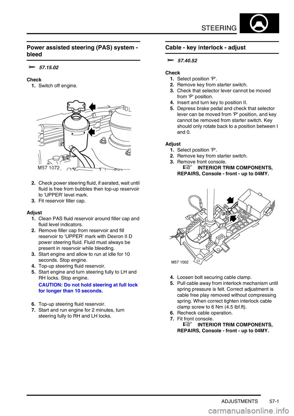
Power assisted steering (PAS) system -
bleed
$% 57.15.02
Check
1.Switch off engine.
2.Check power steering fluid, if aerated, wait until
fluid is free from bubbles then top-up reservoir
to 'UPPER' level mark.
3.Fit reservoir filler cap.
Adjust
1.Clean PAS fluid reservoir around filler cap and
fluid level indicators.
2.Remove filler cap from reservoir and fill
reservoir to 'UPPER' mark with Dexron II D
power steering fluid. Fluid must always be
present in reservoir while bleeding.
3.Start engine and allow to run at idle for 10
seconds. Stop engine.
4.Top-up steering fluid reservoir.
5.Start engine and turn steering fully to LH and
RH locks. Stop engine.
CAUTION: Do not hold steering at full lock
for longer than 10 seconds.
6.Top-up steering fluid reservoir.
7.Start and run engine for 2 minutes, turn
steering fully to RH and LH locks.
Cable - key interlock - adjust
$% 57.40.52
Check
1.Select position 'P'.
2.Remove key from starter switch.
3.Check that selector lever cannot be moved
from 'P' position.
4.Insert and turn key to position II.
5.Depress brake pedal and check that selector
lever can be moved from 'P' position, and key
cannot be removed from starter switch. Key
should only rotate back to a position between I
and 0.
Adjust
1.Select position 'P'.
2.Remove key from starter switch.
3.Remove front console.
+ INTERIOR TRIM COMPONENTS,
REPAIRS, Console - front - up to 04MY.
4.Loosen bolt securing cable clamp.
5.Pull cable away from interlock mechanism until
spring pressure is felt. Correct adjustment is
cable free play removed without compressing
spring. When correct tighten interlock cable
clamp screw to 6 Nm (4.5 lbf.ft).
6.Recheck cable operation.
7.Fit front console.
+ INTERIOR TRIM COMPONENTS,
REPAIRS, Console - front - up to 04MY.