LAND ROVER FRELANDER 2 2006 Repair Manual
Manufacturer: LAND ROVER, Model Year: 2006, Model line: FRELANDER 2, Model: LAND ROVER FRELANDER 2 2006Pages: 3229, PDF Size: 78.5 MB
Page 161 of 3229
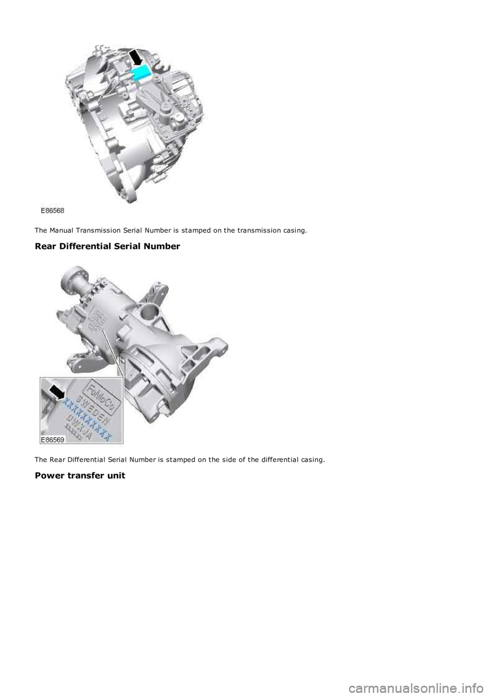
The Manual Trans mi ss i on Serial Number is st amped on t he transmis s ion casi ng.
Rear Differential Serial Number
The Rear Different ial Serial Number is s t amped on t he s ide of t he different ial cas ing.
Power transfer unit
Page 162 of 3229
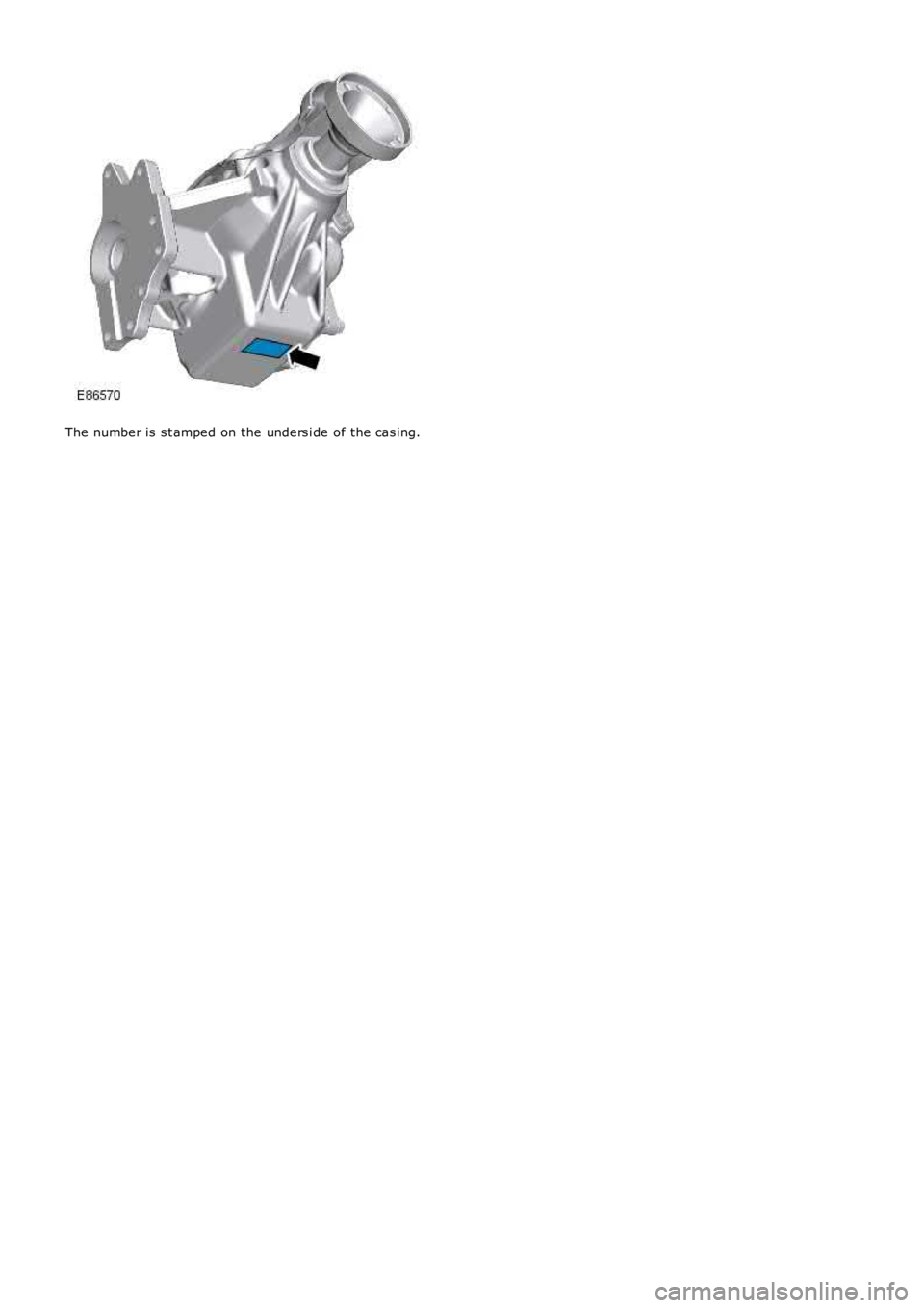
The number is s t amped on the unders i de of the cas ing.
Page 163 of 3229
Publ is hed: 24-Jun-2011
Jacking and Lifting - Jacking
Des cript ion and Operat ion
General
W ARNING: The foll owing i nst ructi ons mus t be adhered to before rais i ng the vehicle off t he ground:
Posi ti on vehi cl e on a sol id, level surface.Apply t he parking brake.Select 'P' - PARK on automat ic t rans mis s ion sel ect or.Select 'N' - Neutral on manual t rans mis s ion.
W ARNING: If t he dri ve s haft(s ) are t o be di sconnect ed, i t wil l be neces s ary t o rai s e all four wheels off the ground inorder t hat t he s haft (s ) can be rot ated. DO NOT us e the cus tomer jack and ens ure that t he vehi cl e is adequatel y s upport edon axle s t ands . W i th the vehicle rai sed, it will be necess ary to releas e t he park brake and sel ect Neutral - 'N' in the mai nt ransmis s ion t o enabl e t he dri ve s haft(s ) to be rot ated.
• CAUTIO NS:
To avoid damage t o t he underbody components of t he vehi cle, the foll owing i ns t ructions mus t be adhered to:
Do not pos it ion jacks or axle s t ands under the foll owing component s :
Body s truct ure ot her t han any approved jacki ng or li ft ing point sRear subframeBumpersFuel l inesFuel t ankBrake l inesFront or rear s uspens ion armsSteering l inkageRear di fferenti al uni tTrans mis s ionEngi ne oil pan - See not e below
• NOTE: For certain repair operat ions, i t may be necess ary to support t he engine under t he oil pan. In thi s cas e, a bl ock ofhardwood or a rubber pad mus t be pos it ioned on t he jack li ft ing pad t o protect the oi l pan.
Hydraulic jack
• W ARNINGS:
Before commenci ng work on undersi de of vehi cl e, ens ure that axle s t ands are correctly pos it ioned and vehi cle i ss ecurel y s upported.
Al ways chock the rear wheel s when jacking t he front of the vehicle.
A hydrauli c jack wi th a mi ni mum li ft ing capacit y of 1500 kg, (3,300 l bs) must be us ed.
Raising and Supporting the Vehicle
To as si s t in rais ing the vehicle, us e t he cus t omer jacki ng poi nts on the s i ll or on t he trolley jack pos i ti on at the rear of t hefront subframe as indicated i n t he fol lowing ill ust rat ions .
Raising the front of the vehicle
W ARNING: Always chock t he rear wheels when jacki ng the front of t he vehi cl e.
Apply t he parking brake.
Select 'P' - Park on aut omat ic trans mi s si on s el ect or.
Select 'N' - Neutral on manual t rans mis s ion.
Page 164 of 3229
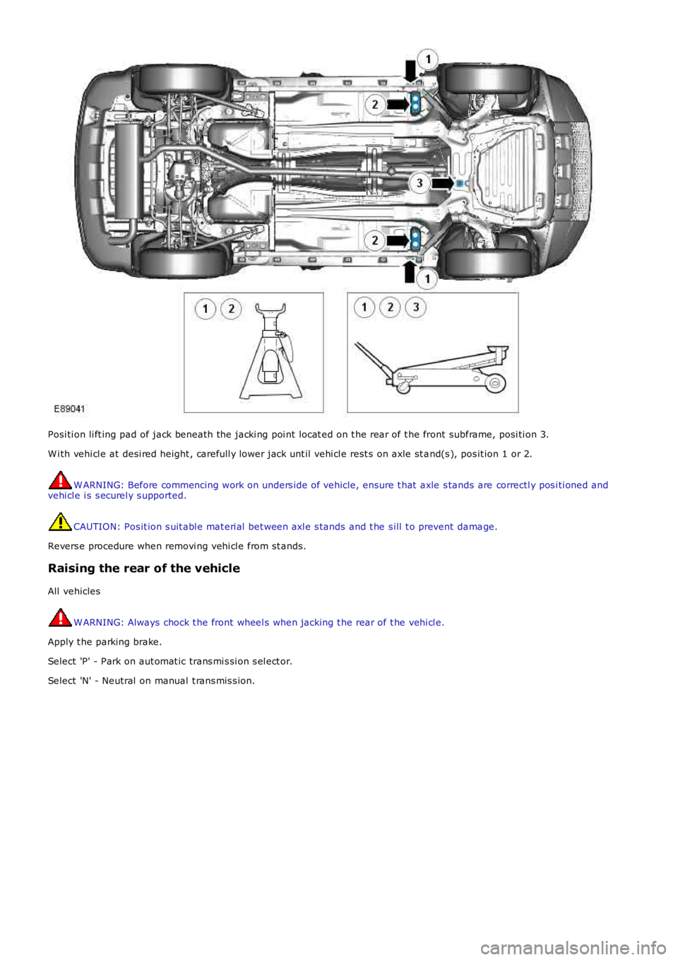
Posi ti on li ft ing pad of jack beneath the jacki ng poi nt locat ed on t he rear of t he front subframe, posi ti on 3.
W i th vehi cl e at desi red height , carefull y lower jack unt il vehi cl e rest s on axle st and(s ), pos it ion 1 or 2.
W ARNING: Before commencing work on unders ide of vehicle, ensure t hat axle s tands are correctl y pos i ti oned andvehi cl e i s s ecurel y s upported.
CAUTION: Pos it ion s uit abl e mat eri al bet ween axl e s tands and t he s ill t o prevent damage.
Revers e procedure when removi ng vehi cl e from st ands.
Raising the rear of the vehicle
All vehicles
W ARNING: Always chock t he front wheel s when jacking t he rear of t he vehi cl e.
Apply t he parking brake.
Select 'P' - Park on aut omat ic trans mi s si on s el ect or.
Select 'N' - Neutral on manual t rans mis s ion.
Page 165 of 3229
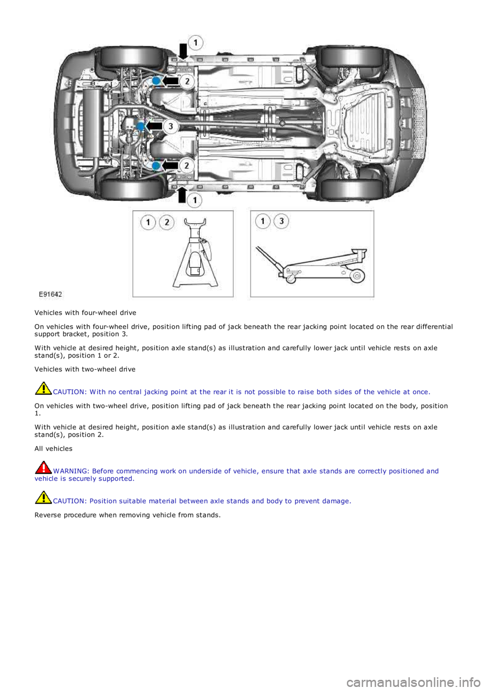
Vehicles wi th four-wheel drive
On vehicles wi th four-wheel drive, posi ti on li ft ing pad of jack beneath the rear jacki ng poi nt located on t he rear di fferenti als upport bracket , pos it ion 3.
W i th vehi cl e at desi red height , pos i ti on axl e s tand(s ) as i ll us t rat ion and careful ly lower jack unti l vehicle res ts on axl es tand(s ), pos i ti on 1 or 2.
Vehicles wi th two-wheel dri ve
CAUTION: W it h no cent ral jacking poi nt at t he rear i t is not pos si ble t o rais e both s ides of the vehicle at once.
On vehicles wi th two-wheel drive, pos i ti on li ft ing pad of jack beneat h t he rear jacking poi nt locat ed on t he body, pos it ion1.
W i th vehi cl e at desi red height , pos i ti on axl e s tand(s ) as i ll us t rat ion and careful ly lower jack unti l vehicle res ts on axl es tand(s ), pos i ti on 2.
All vehicles
W ARNING: Before commencing work on unders ide of vehicle, ensure t hat axle s tands are correctl y pos i ti oned andvehi cl e i s s ecurel y s upported.
CAUTION: Pos it ion s uit abl e mat eri al bet ween axl e s tands and body to prevent damage.
Revers e procedure when removi ng vehi cl e from st ands.
Page 166 of 3229
Publi s hed: 11-May-2011
Jacking and Lifting - Lifting
Des cript ion and Operat ion
Two-Post Lift
W ARNING: Make sure t hat t he vehicle i s s table before commencing work.
CAUTION: If the drive s haft (s ) are to be removed, rel eas e t he parking brake and s el ect NEUTRAL 'N' i n t het ransmis s ion i n order t hat t he s haft (s ) can be rot ated when the vehicle is rais ed to the des ired height.
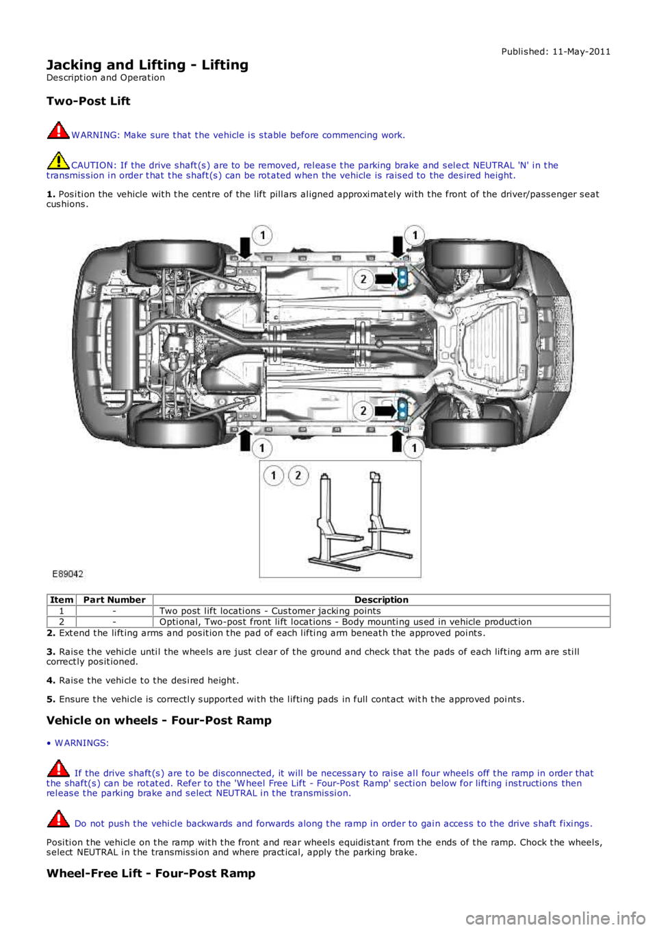
1. Pos i ti on the vehicle wit h t he cent re of the l ift pill ars al igned approxi mat el y wi th t he front of the driver/pass enger s eatcus hions .
ItemPart NumberDescription
1-Two post l ift locati ons - Cus t omer jacki ng points2-Opti onal, Two-pos t front li ft l ocat ions - Body mounti ng us ed in vehicle product ion
2. Ext end t he li ft ing arms and pos it ion t he pad of each l ifti ng arm beneat h t he approved poi nt s .
3. Rais e t he vehi cl e unti l the wheels are just cl ear of t he ground and check t hat the pads of each lift ing arm are s ti llcorrect ly pos it ioned.
4. Rais e t he vehi cl e t o t he des i red height .
5. Ensure t he vehi cl e is correctl y s upport ed wi th the l ifti ng pads in full cont act with t he approved poi nt s .
Vehicle on wheels - Four-Post Ramp
• W ARNINGS:
If the drive s haft (s ) are t o be dis connected, it will be necess ary to rais e al l four wheel s off t he ramp in order thatt he shaft(s ) can be rot at ed. Refer to the 'W heel Free Lift - Four-Pos t Ramp' s ecti on below for li ft ing i ns t ructi ons thenrel eas e t he parki ng brake and s elect NEUTRAL i n t he transmis si on.
Do not pus h t he vehi cl e backwards and forwards along t he ramp in order to gai n acces s t o the drive s haft fixi ngs .
Posi ti on t he vehi cl e on t he ramp wit h t he front and rear wheel s equidis t ant from t he ends of t he ramp. Chock t he wheel s,s elect NEUTRAL i n t he transmis si on and where pract ical, apply the parki ng brake.
Wheel-Free Lift - Four-Post Ramp
Page 167 of 3229
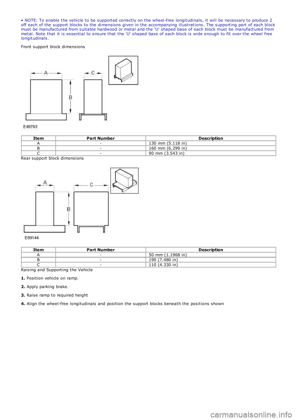
• NOTE: To enable t he vehi cle t o be s upport ed correctl y on t he wheel -free longit udi nal s, i t wil l be neces s ary t o produce 2off each of the support blocks t o the di mens ions given in the accompanying ill ust rations . The s upport ing part of each bl ockmus t be manufactured from s uit able hardwood or met al and the 'U' shaped bas e of each bl ock mus t be manufact ured frommet al . Note that it i s es sent ial to ens ure that t he 'U' s haped bas e of each block is wide enough to fit over t he wheel freelongit udinals .
Front s upport bl ock di mens ions
ItemPart NumberDescriptionA-130 mm (5.118 in)
B-160 mm (6.299 in)
C-90 mm (3.543 in)Rear support block dimens i ons
ItemPart NumberDescription
A-50 mm (1.1968 in)B-190 (7.480 in)
C-110 (4.330 in)
Rais ing and Support ing t he Vehicle
1. Posi ti on vehi cl e on ramp.
2. Appl y parking brake.
3. Rais e ramp t o required height
4. Ali gn the wheel -free l ongi tudinals and pos it ion the s upport blocks beneat h the pos it ions s hown
Page 168 of 3229
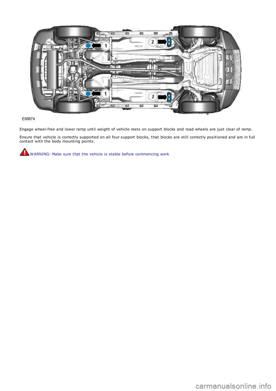
Engage wheel-free and l ower ramp unt il weight of vehi cl e res t s on s upport blocks and road wheels are jus t clear of ramp.
Ensure t hat vehicle is correct ly support ed on all four s upport blocks, t hat bl ocks are s ti ll correct ly pos it ioned and are in fullcont act wit h the body mount ing point s .
W ARNING: Make sure t hat t he vehicle i s s table before commencing work
Page 169 of 3229
Publi s hed: 11-May-2011
Jacking and Lifting - Vehicle Recovery
Des cript ion and Operat ion
Towing Points
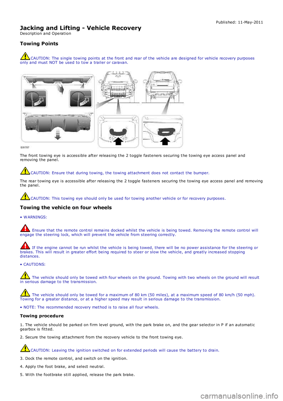
CAUTION: The s ingle towi ng poi nts at t he front and rear of t he vehi cl e are des igned for vehicl e recovery purpos esonly and mus t NOT be used to t ow a trail er or caravan.
The front towi ng eye is acces s ibl e aft er releas ing t he 2 t oggle fast eners s ecuring the t owing eye acces s panel andremovi ng the panel.
CAUTION: Ens ure t hat during t owing, the towi ng att achment does not contact t he bumper.
The rear t owing eye i s acces si ble after rel eas i ng the 2 toggle fas teners securi ng the towing eye access panel and removingt he panel.
CAUTION: This t owing eye s hould onl y be us ed for t owing another vehi cl e or for recovery purpos es .
Towing the vehicle on four wheels
• W ARNINGS:
Ens ure t hat the remote cont rol remai ns docked whil s t the vehicle is being towed. Removi ng the remot e cont rol wi llengage t he s t eering l ock, which wi ll prevent the vehicle from s t eering correct ly.
If the engine cannot be run whi ls t t he vehi cl e i s bei ng t owed, t here wi ll be no power as si s tance for t he s teeri ng orbrakes. Thi s wil l res ult in greater effort bei ng required to st eer or sl ow t he vehi cl e, and greatl y increas ed s toppingdis t ances.
• CAUTIO NS:
The vehicle s hould onl y be t owed wit h four wheels on the ground. Towing wi th two wheel s on t he ground wi ll res ultin serious damage t o t he trans mi s si on.
The vehicle s hould onl y be t owed for a maxi mum of 80 km (50 mil es), at a maximum s peed of 80 km/h (50 mph).Towing for a great er di st ance, or at a higher s peed may res ult i n s eri ous damage t o t he t rans mis s ion.
• NOTE: The recommended recovery met hod is to rais e al l four wheel s.
Towing procedure
1. The vehi cl e s houl d be parked on firm level ground, wi th t he park brake on, and the gear s el ect or in P if an aut omati cgearbox is fit t ed.
2. Secure the towing at t achment from the recovery vehicle to the front t owing eye.
CAUTION: Leavi ng the ignit ion s wi tched on for extended peri ods wil l caus e the bat tery t o drai n.
3. Dock the remote cont rol, and s wi tch on t he igni ti on.
4. Appl y t he foot brake, and s el ect neutral.
5. W i th the foot brake s t ill appli ed, releas e the park brake.
Page 170 of 3229
6. The vehi cl e can now be t owed a maxi mum of 80 km (50 mil es) at a maxi mum speed of 80 km/h (50 mph).
7. Upon arrival at t he des ti nat ion, ensure wherever pos s ibl e that t he vehi cl e i s par
ked on firm l evel ground.
8. Appl y t he park brake, and place t he s el ect or lever into the P pos i ti on.
9. Swit ch off t he ignit ion, and remove t he remote control. W ARNING: Use ext reme caut ion when det aching towing equi pment . Vehi cle movement is po
s s ible which can res ult i n
s erious i njuri es.
10. Remove the t owing at tachment from t he t owing eye.
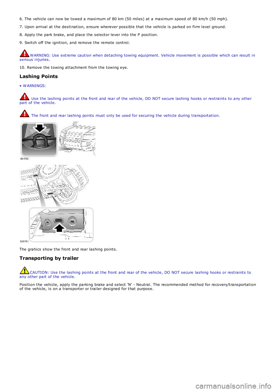
Lashing Points
• W ARNINGS: Us e t he las hing poi nt s at t he front and rear of the vehicle, DO NOT s ecure las hing
hooks or res traint s to any other
part of t he vehi cl e. The front and rear l as hing poi nt s mus t only be used for s ecuri ng t he vehi cl e duri ng
trans port ati on.The grahics s how t he front and rear las hing point s .
Transporting by trailer CAUTION: Us e t he las hing point s at t he front and rear of the vehicle, DO NOT s ecure
las hing hooks or res traint s to
any other part of t he vehi cl e.
Posi ti on t he vehi cl e, apply the parki ng brake and s elect 'N' - Neutral. The recommen ded met hod for recovery/t rans portat ion
of the vehicle, i s on a t rans port er or t rai ler desi gned for t hat purpos e.