LAND ROVER FRELANDER 2 2006 Repair Manual
FRELANDER 2 2006
LAND ROVER
LAND ROVER
https://www.carmanualsonline.info/img/64/57251/w960_57251-0.png
LAND ROVER FRELANDER 2 2006 Repair Manual
Trending: jump start, interior lights, lumbar support, manual radio set, low beam, auxiliary battery, fuse
Page 1901 of 3229
Publi s hed: 11-May-2011
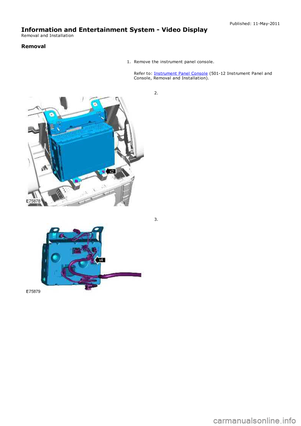
Information and Entertainment System - Video Display
Removal and Inst all ati on
Removal
Remove t he ins trument panel cons ole.
Refer t o: Ins trument Panel Consol e (501-12 Ins t rument Panel andConsol e, Removal and Ins t al lat ion).
1.
2.
3.
Page 1902 of 3229
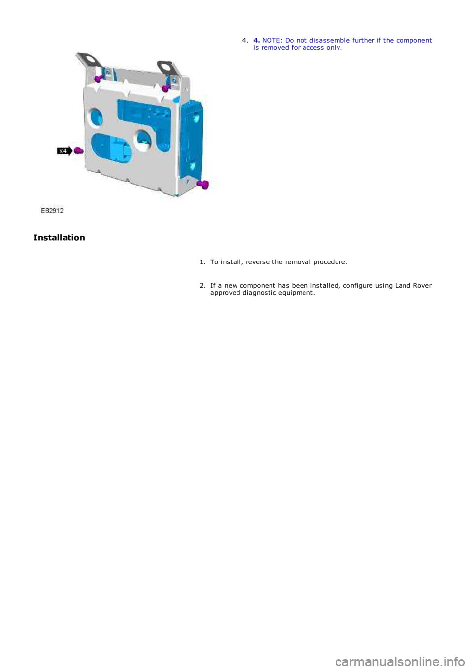
4. NOTE: Do not dis ass embl e further if t he componenti s removed for acces s onl y.4.
Installation
To i nst all , revers e t he removal procedure.1.
If a new component has been ins t al led, configure usi ng Land Roverapproved diagnos t ic equipment .2.
Page 1903 of 3229
Publi s hed: 11-May-2011
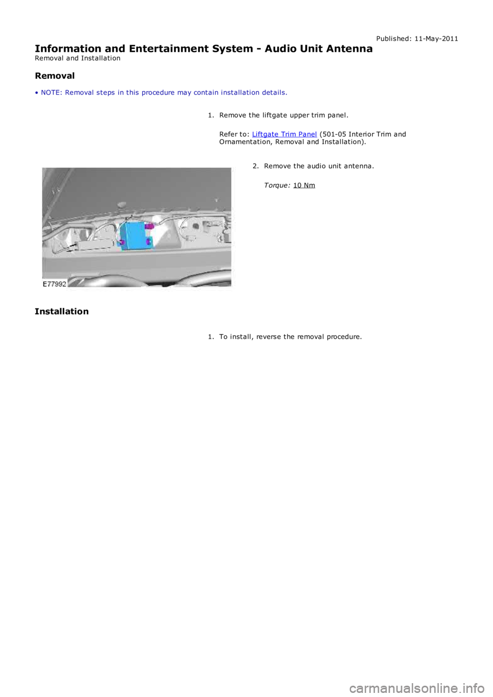
Information and Entertainment System - Audio Unit Antenna
Removal and Inst all ati on
Removal
• NOTE: Removal s t eps in t his procedure may cont ain i nst all ati on det ail s.
Remove t he li ft gat e upper trim panel .
Refer t o: Li ft gate Trim Panel (501-05 Interi or Trim and
Ornament ati on, Removal and Ins tal lat ion).
1. Remove t he audi o unit antenna.
T orque: 10 Nm 2.
Installation To i nst all , revers e t he removal procedure.
1.
Page 1904 of 3229
Publi s hed: 11-May-2011
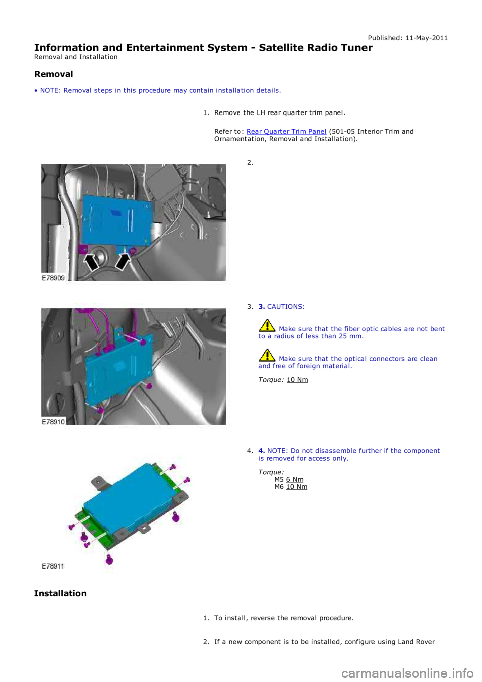
Information and Entertainment System - Satellite Radio Tuner
Removal and Inst all ati on
Removal
• NOTE: Removal s t eps in t his procedure may cont ain i nst all ati on det ail s.
Remove t he LH rear quart er trim panel .
Refer t o: Rear Quarter Tri m Panel (501-05 Int erior Tri m and
Ornament ati on, Removal and Ins tal lat ion).
1. 2.
3.
CAUTIONS: Make s ure that t he fi ber opt ic cables are not bent
t o a radius of les s t han 25 mm. Make s ure that t he opti cal connectors are cl ean
and free of foreign mat eri al.
T orque: 10 Nm 3.
4.
NOTE: Do not dis ass embl e further if t he component
i s removed for acces s onl y.
T orque: M5 6 Nm M6
10 Nm 4.
Installation To i nst all , revers e t he removal procedure.
1.
If a new component i s t o be ins t al led, configure usi ng Land Rover
2.
Page 1905 of 3229
Publi s hed: 11-May-2011
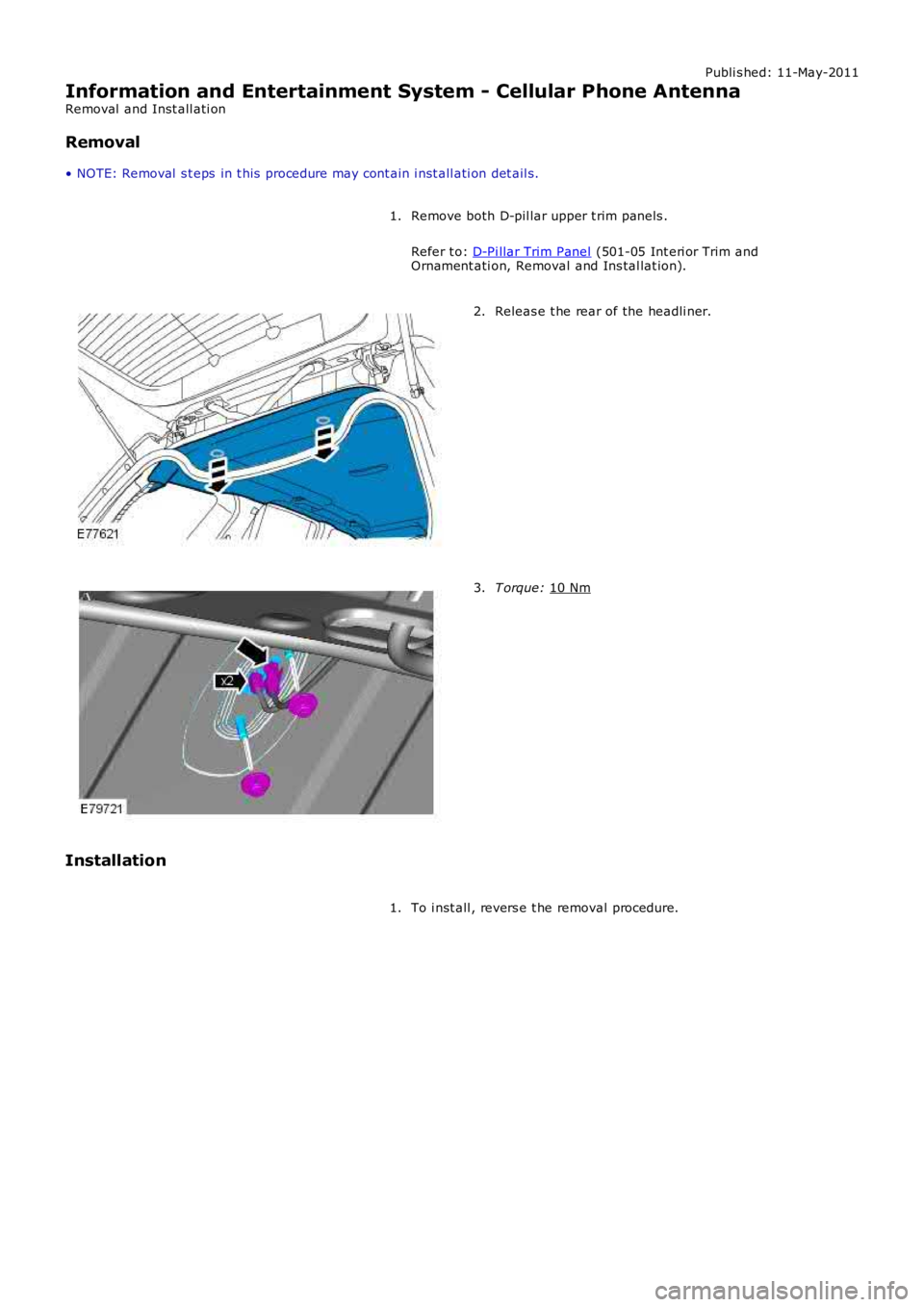
Information and Entertainment System - Cellular Phone Antenna
Removal and Inst all ati on
Removal
• NOTE: Removal s t eps in t his procedure may cont ain i nst all ati on det ail s.
Remove both D-pil lar upper t rim panels .
Refer t o: D-Pi llar Trim Panel (501-05 Int eri or Trim and
Ornament ati on, Removal and Ins tal lat ion).
1. Releas e t he rear of the headli ner.
2. T orque:
10 Nm 3.
Installation To i nst all , revers e t he removal procedure.
1.
Page 1906 of 3229
Publi s hed: 11-May-2011
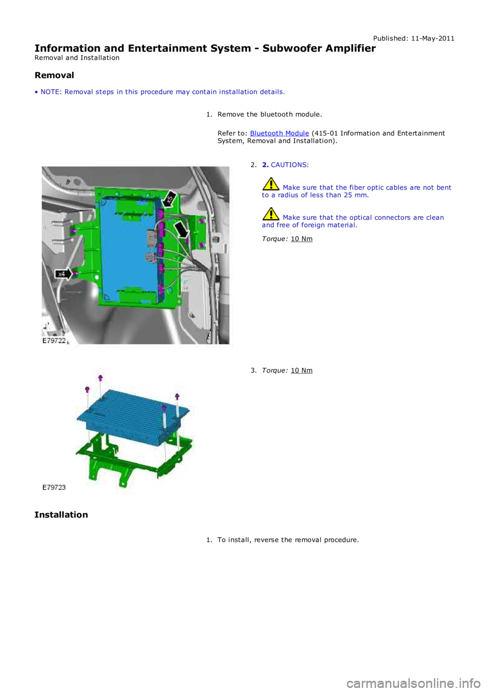
Information and Entertainment System - Subwoofer Amplifier
Removal and Inst all ati on
Removal
• NOTE: Removal s t eps in t his procedure may cont ain i nst all ati on det ail s.
Remove t he bluetoot h module.
Refer t o: Bluetoot h Modul e (415-01 Informat ion and Ent ert ainment
Syst em, Removal and Ins tall ati on).
1. 2.
CAUTIONS: Make s ure that t he fi ber opt ic cables are not bent
t o a radius of les s t han 25 mm. Make s ure that t he opti cal connectors are cl ean
and free of foreign mat eri al.
T orque: 10 Nm 2.
T orque:
10 Nm 3.
Installation To i nst all , revers e t he removal procedure.
1.
Page 1907 of 3229
Publi s hed: 11-May-2011
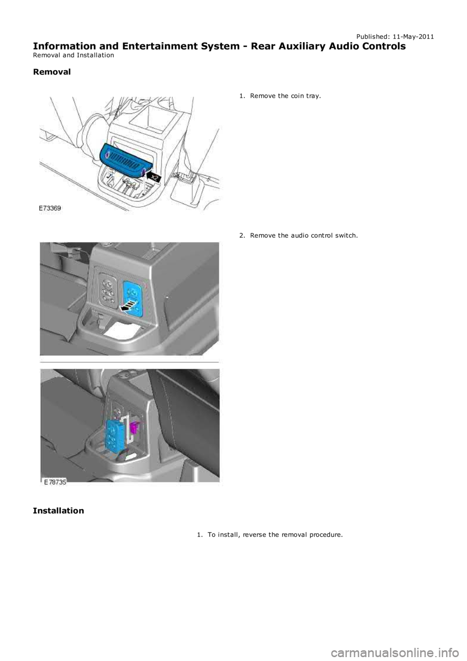
Information and Entertainment System - Rear Auxiliary Audio Controls
Removal and Inst all ati on
Removal
Remove t he coi n t ray.1.
Remove t he audi o cont rol s wit ch.2.
Installation
To i nst all , revers e t he removal procedure.1.
Page 1908 of 3229
Publi s hed: 11-May-2011
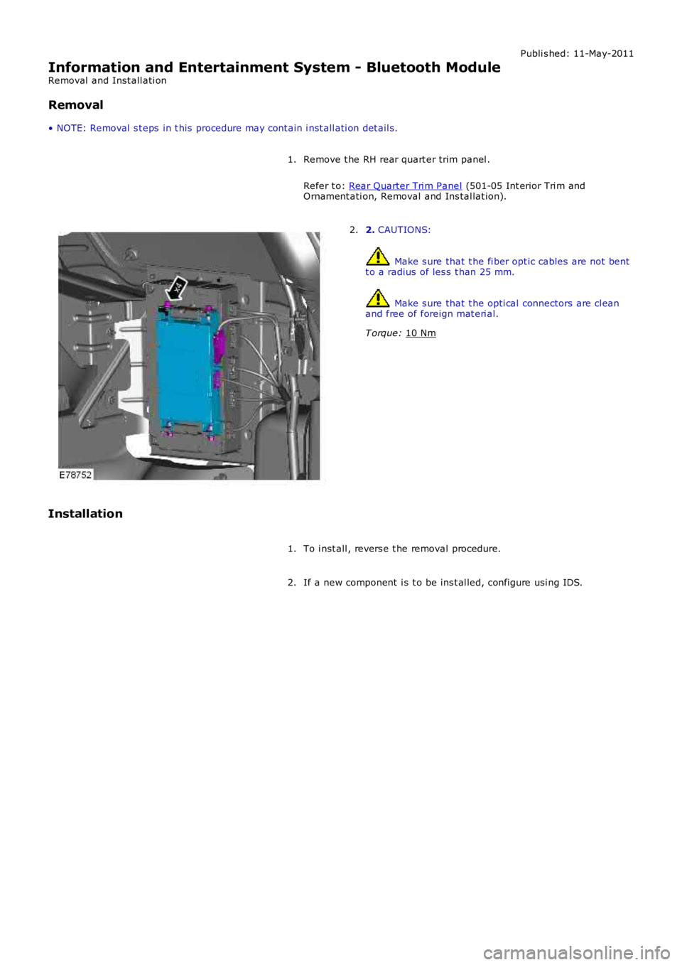
Information and Entertainment System - Bluetooth Module
Removal and Inst all ati on
Removal
• NOTE: Removal s t eps in t his procedure may cont ain i nst all ati on det ail s.
Remove t he RH rear quart er trim panel .
Refer t o: Rear Quarter Tri m Panel (501-05 Int erior Tri m and
Ornament ati on, Removal and Ins tal lat ion).
1. 2.
CAUTIONS: Make s ure that t he fi ber opt ic cables are not bent
t o a radius of les s t han 25 mm. Make s ure that t he opti cal connectors are cl ean
and free of foreign mat eri al.
T orque: 10 Nm 2.
Installation To i nst all , revers e t he removal procedure.
1.
If a new component i s t o be ins t al led, configure usi ng IDS.
2.
Page 1909 of 3229
Publi s hed: 11-May-2011
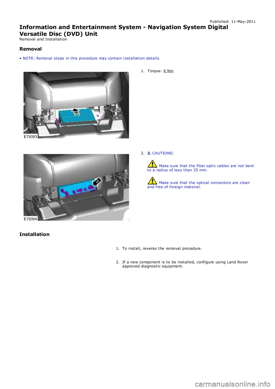
Information and Entertainment System - Navigation System Digital
Versatile Disc (DVD) Unit
Removal and Inst all ati on
Removal
• NOTE: Removal s t eps in t his procedure may cont ain i nst all ati on det ail s. T orque:
6 Nm 1.
2.
CAUTIONS: Make s ure that t he fi ber opt ic cables are not bent
t o a radius of les s t han 25 mm. Make s ure that t he opti cal connectors are cl ean
and free of foreign mat eri al.
2.
Installation To i nst all , revers e t he removal procedure.
1.
If a new component i s t o be ins t al led, configure usi ng Land Rover
approved diagnos t ic equipment .
2.
Page 1910 of 3229
Publi s hed: 11-May-2011
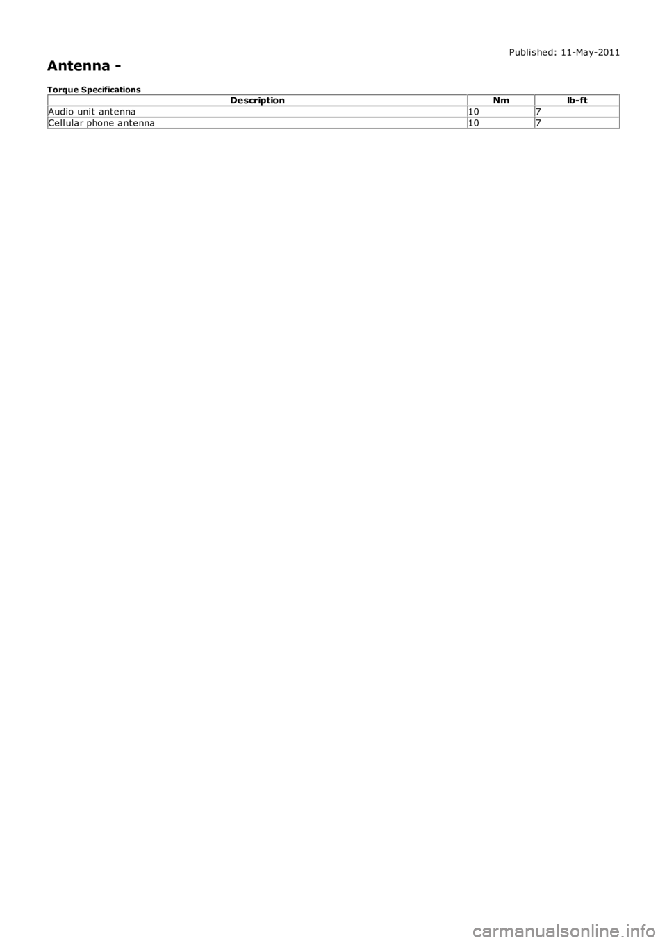
Antenna -
Torque SpecificationsDescriptionNmlb-ft
Audio uni t ant enna107
Cell ular phone ant enna107
Trending: low oil pressure, jump start terminals, gas type, clock, load capacity, infotainment, blower
