length LAND ROVER FRELANDER 2 2006 Repair Manual
[x] Cancel search | Manufacturer: LAND ROVER, Model Year: 2006, Model line: FRELANDER 2, Model: LAND ROVER FRELANDER 2 2006Pages: 3229, PDF Size: 78.5 MB
Page 174 of 3229
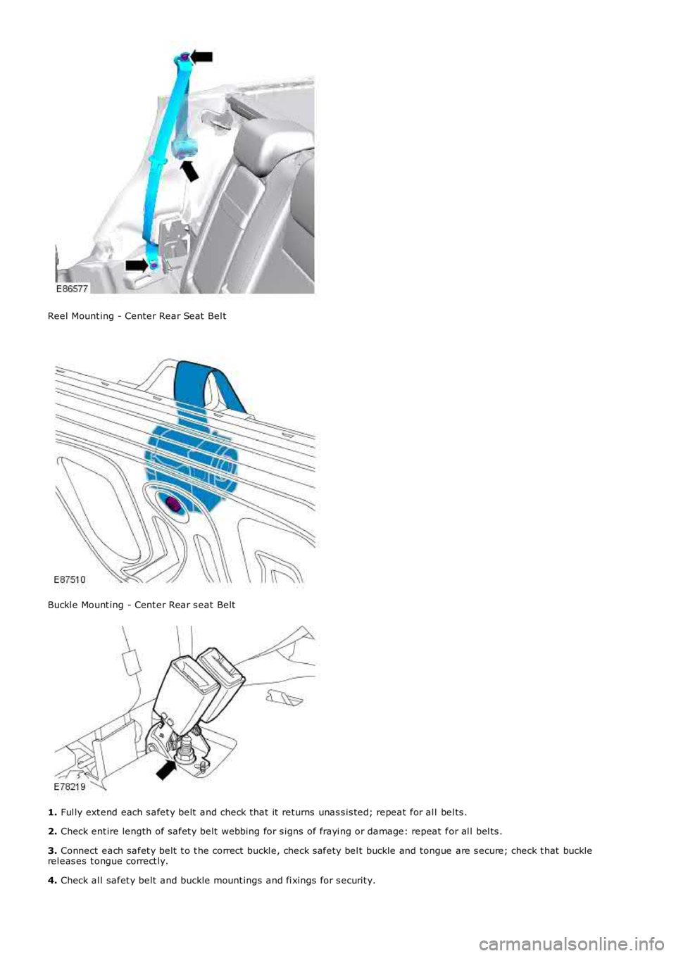
Reel Mount ing - Center Rear Seat Bel t
Buckl e Mount ing - Cent er Rear s eat Belt
1. Ful ly ext end each s afet y belt and check that it returns unas s is ted; repeat for al l bel ts .
2. Check ent ire length of safet y belt webbing for s igns of frayi ng or damage: repeat for al l bel ts .
3. Connect each safet y belt t o t he correct buckl e, check s afety bel t buckle and tongue are s ecure; check t hat bucklerel eas es t ongue correct ly.
4. Check al l safet y belt and buckle mount ings and fi xings for s ecurit y.
Page 185 of 3229
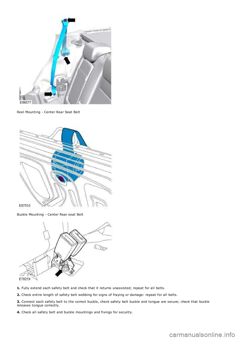
Reel Mount ing - Center Rear Seat Bel t
Buckl e Mount ing - Cent er Rear s eat Belt
1.
Ful ly ext end each s afet y belt and check that it returns unas s is ted; repeat for al l bel ts .
2. Check ent ire length of safet y belt webbing for s igns of frayi ng or damage: repeat f or al l bel ts .
3. Connect each safet y belt t o t he correct buckl e, check s afety bel t buckle and tongue are s ecure; check t hat buckle
rel eas es t ongue correct ly.
4. Check al l safet y belt and buckle mount ings and fi xings for s ecurit y.
Page 603 of 3229
Publi s hed: 23-Aug-2011
Engine - I6 3.2L Petrol -
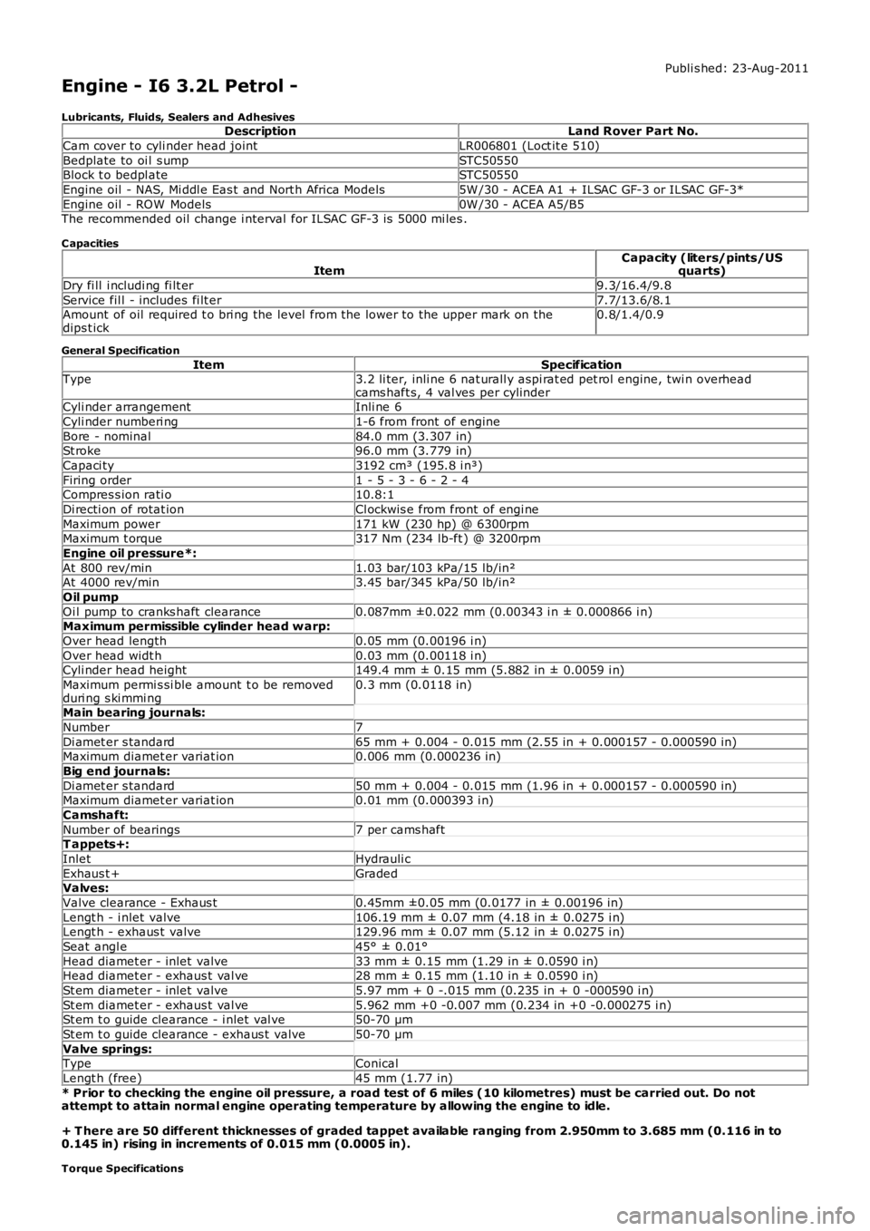
Lubricants, Fluids, Sealers and AdhesivesDescriptionLand Rover Part No.
Cam cover to cyli nder head jointLR006801 (Loct it e 510)
Bedplate to oi l s umpSTC50550Block t o bedpl ateSTC50550
Engine oil - NAS, Mi ddl e Eas t and Nort h Africa Models5W /30 - ACEA A1 + ILSAC GF-3 or ILSAC GF-3*
Engine oil - ROW Models0W /30 - ACEA A5/B5The recommended oil change i nterval for ILSAC GF-3 is 5000 mi les .
C apacities
ItemCapacity (liters/pints/USquarts)
Dry fi ll i ncludi ng fi lt er9.3/16.4/9.8
Service fil l - includes fi lt er7.7/13.6/8.1Amount of oil required t o bri ng the level from the lower to the upper mark on thedips t ick0.8/1.4/0.9
General Specification
ItemSpecificationType3.2 li ter, inli ne 6 nat urall y aspi rat ed pet rol engine, twi n overheadcams haft s, 4 val ves per cylinderCyli nder arrangementInli ne 6
Cyli nder numberi ng1-6 from front of engine
Bore - nominal84.0 mm (3.307 in)St roke96.0 mm (3.779 in)
Capaci ty3192 cm³ (195.8 i n³)
Firing order1 - 5 - 3 - 6 - 2 - 4Compres s ion rati o10.8:1
Di recti on of rotat ionCl ockwis e from front of engi ne
Maximum power171 kW (230 hp) @ 6300rpmMaximum t orque317 Nm (234 lb-ft ) @ 3200rpm
Engine oil pressure*:
At 800 rev/min1.03 bar/103 kPa/15 lb/in²At 4000 rev/min3.45 bar/345 kPa/50 lb/in²
Oil pump
Oi l pump to cranks haft clearance0.087mm ±0.022 mm (0.00343 i n ± 0.000866 i n)Maximum permissible cylinder head w arp:
Over head length0.05 mm (0.00196 i n)
Over head widt h0.03 mm (0.00118 i n)Cyli nder head height149.4 mm ± 0.15 mm (5.882 in ± 0.0059 i n)
Maximum permi s si ble amount t o be removedduri ng s ki mmi ng0.3 mm (0.0118 in)
Main bearing journals:
Number7
Di amet er s tandard65 mm + 0.004 - 0.015 mm (2.55 in + 0.000157 - 0.000590 in)Maximum diamet er variat ion0.006 mm (0.000236 in)
Big end journals:
Di amet er s tandard50 mm + 0.004 - 0.015 mm (1.96 in + 0.000157 - 0.000590 in)Maximum diamet er variat ion0.01 mm (0.000393 i n)
Camshaft:
Number of bearings7 per cams haftT appets+:
InletHydrauli c
Exhaus t +GradedValves:
Valve clearance - Exhaus t0.45mm ±0.05 mm (0.0177 in ± 0.00196 in)
Lengt h - i nlet valve106.19 mm ± 0.07 mm (4.18 in ± 0.0275 i n)Lengt h - exhaus t valve129.96 mm ± 0.07 mm (5.12 in ± 0.0275 i n)
Seat angl e45° ± 0.01°
Head diamet er - inlet valve33 mm ± 0.15 mm (1.29 in ± 0.0590 i n)Head diamet er - exhaus t val ve28 mm ± 0.15 mm (1.10 in ± 0.0590 i n)
St em diamet er - inlet valve5.97 mm + 0 -.015 mm (0.235 in + 0 -000590 i n)
St em diamet er - exhaus t val ve5.962 mm +0 -0.007 mm (0.234 in +0 -0.000275 i n)St em t o guide clearance - i nlet val ve50-70 µm
St em t o guide clearance - exhaus t valve50-70 µm
Valve springs:TypeConical
Lengt h (free)45 mm (1.77 in)
* Prior to checking the engine oil pressure, a road test of 6 miles (10 kilometres) must be carried out. Do notattempt to attain normal engine operating temperature by allowing the engine to idle.
+ T here are 50 different thicknesses of graded tappet available ranging from 2.950mm to 3.685 mm (0.116 in to0.145 in) rising in increments of 0.015 mm (0.0005 in).
Torque Specifications
Page 630 of 3229
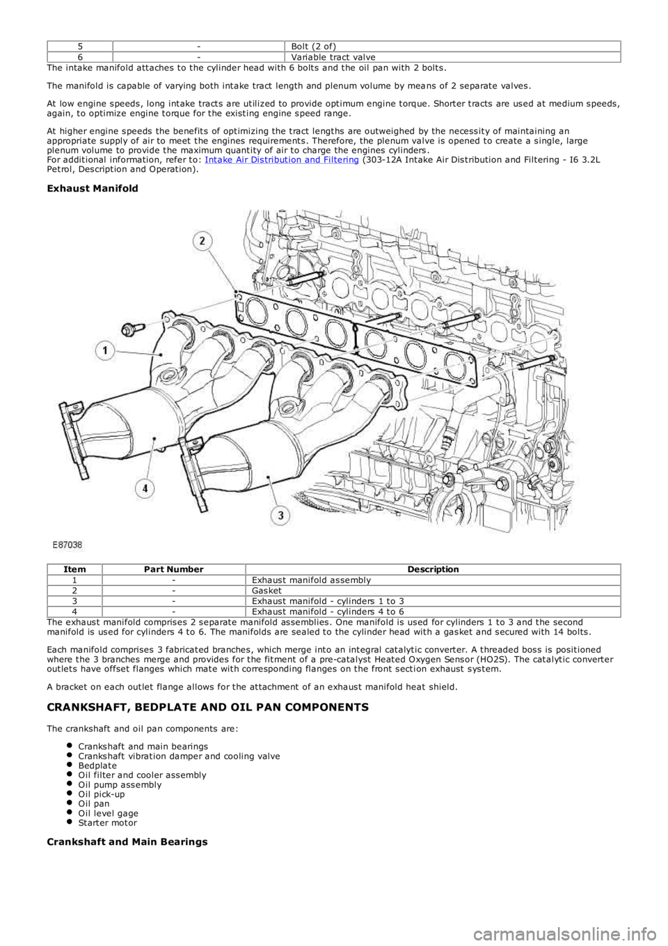
5-Bolt (2 of)6-Variable tract valveThe intake manifold att aches t o t he cylinder head wit h 6 bolt s and t he oil pan with 2 bolt s .
The manifold is capable of varying both int ake tract length and plenum volume by means of 2 separat e valves .
At low engine s peeds , long int ake tract s are ut iliz ed to provide opt imum engine t orque. Short er t racts are us ed at medium s peeds ,again, t o optimiz e engine t orque for t he exist ing engine s peed range.
At higher engine s peeds the benefit s of opt imizing t he t ract lengt hs are outweighed by the necess it y of maintaining anappropriate supply of air to meet t he engines requirement s . Therefore, t he plenum valve is opened t o create a s ingle, largeplenum volume to provide t he maximum quant ity of air t o charge the engines cylinders.For addit ional information, refer t o: Int ake Air Dis tribut ion and Filtering (303-12A Int ake Air Dis t ribution and Filt ering - I6 3.2LPet rol, Des cript ion and O perat ion).
Exhaust Manifold
ItemPart NumberDescription1-Exhaus t manifold as sembly2-Gas ket3-Exhaus t manifold - cylinders 1 t o 34-Exhaus t manifold - cylinders 4 t o 6The exhaus t manifold compris es 2 s eparat e manifold as semblies . One manifold is us ed for cylinders 1 t o 3 and t he secondmanifold is us ed for cylinders 4 t o 6. The manifolds are sealed t o the cylinder head wit h a gas ket and s ecured with 14 bolts .
Each manifold comprises 3 fabricat ed branches , which merge int o an int egral cat alyt ic convert er. A t hreaded bos s is posit ionedwhere t he 3 branches merge and provides for t he fit ment of a pre-catalyst Heat ed O xygen Sens or (HO2S). The cat alyt ic convert erout let s have offset flanges which mat e wit h corresponding flanges on t he front s ect ion exhaust s ys t em.
A bracket on each out let flange allows for t he at t achment of an exhaus t manifold heat shield.
CRANKSHAFT, BEDPLATE AND OIL PAN COMPONENTS
The crankshaft and oil pan components are:
Cranks haft and main bearingsCranks haft vibrat ion damper and cooling valveBedplat eO il filter and cooler ass emblyO il pump ass emblyO il pick-upO il panO il level gageSt art er mot or
Crankshaft and Main Bearings
Page 785 of 3229
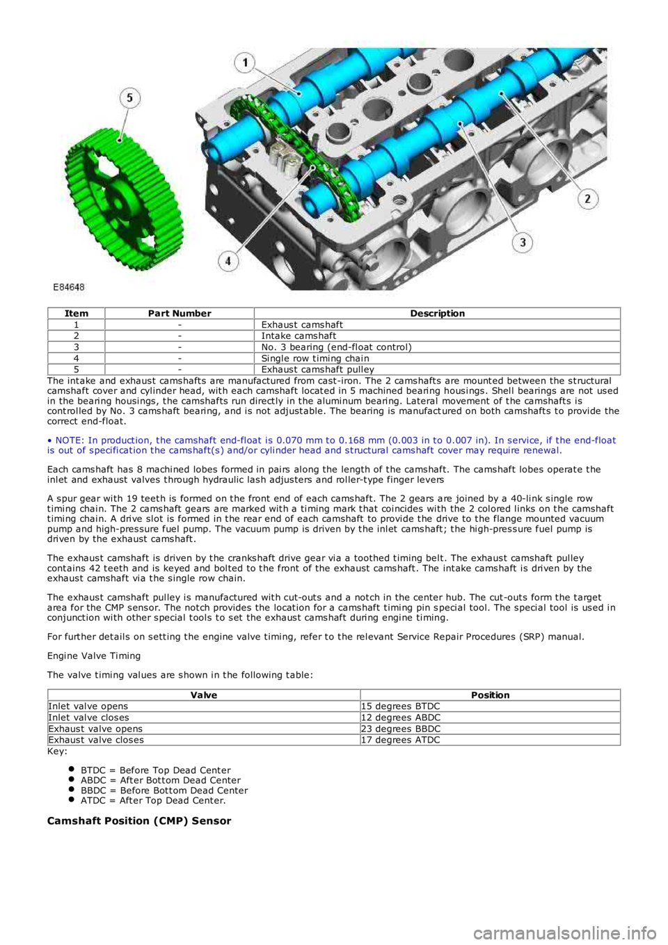
ItemPart NumberDescription
1-Exhaus t cams haft2-Intake cams haft
3-No. 3 bearing (end-fl oat control)
4-Si ngl e row t imi ng chai n5-Exhaus t cams haft pull ey
The int ake and exhaus t cams haft s are manufactured from cast -iron. The 2 cams haft s are mount ed between the s t ructuralcamshaft cover and cyl inder head, wit h each camshaft locat ed i n 5 machined beari ng hous i ngs . Shel l bearings are not us edin the beari ng housi ngs , t he camshafts run direct ly in t he alumi num beari ng. Lateral movement of t he camshaft s i scont rol led by No. 3 cams haft beari ng, and i s not adjust able. The bearing is manufactured on both camshaft s t o provi de thecorrect end-float.
• NOTE: In product ion, t he camshaft end-fl oat i s 0.070 mm t o 0.168 mm (0.003 in t o 0.007 in). In s ervi ce, if t he end-floatis out of s peci fi cat ion t he cams haft(s ) and/or cyli nder head and s t ructural cams haft cover may requi re renewal.
Each cams haft has 8 machi ned lobes formed in pai rs al ong the length of t he cams haft. The cams haft lobes operat e t heinl et and exhaust valves t hrough hydraulic las h adjus ters and rol ler-t ype finger levers
A s pur gear wi th 19 teet h is formed on t he front end of each cams haft. The 2 gears are joined by a 40-li nk s ingle rowt imi ng chai n. The 2 cams haft gears are marked wit h a ti ming mark t hat coi ncides wi th the 2 col ored l inks on t he camshaftt imi ng chai n. A dri ve sl ot is formed in t he rear end of each camshaft to provi de t he drive to t he flange mounted vacuumpump and high-pres sure fuel pump. The vacuum pump is driven by t he inl et cams haft ; the hi gh-pres s ure fuel pump isdri ven by the exhaust cams haft .
The exhaus t camshaft is driven by t he cranks haft drive gear vi a a toothed t iming belt . The exhaus t camshaft pul leycont ains 42 t eeth and is keyed and bol ted to t he front of the exhaust cams haft . The int ake cams haft i s dri ven by theexhaus t camshaft vi a t he s ingle row chain.
The exhaus t camshaft pul ley i s manufactured wit h cut-out s and a not ch in the center hub. The cut -out s form t he t argetarea for the CMP s ens or. The not ch provides the locat ion for a cams haft t imi ng pin speci al tool. The s peci al tool is us ed i nconjunct ion wi th other s pecial t ool s t o s et the exhaus t cams haft duri ng engi ne ti ming.
For furt her det ail s on s ett ing t he engine valve t imi ng, refer t o t he rel evant Service Repair Procedures (SRP) manual.
Engi ne Valve Ti ming
The valve t imi ng val ues are s hown i n t he fol lowing t able:
ValvePositionInlet val ve opens15 degrees BTDC
Inlet val ve clos es12 degrees ABDC
Exhaus t valve opens23 degrees BBDCExhaus t valve clos es17 degrees ATDC
Key:
BTDC = Before Top Dead Cent erABDC = Aft er Bot t om Dead CenterBBDC = Before Bot t om Dead CenterATDC = Aft er Top Dead Cent er.
Camshaft Position (CMP) Sensor
Page 1156 of 3229
A polyfibre porous duct provi di ng low int ake noi se, di rects ai r into the bas e of t he ri gid i njecti on-molded ai r fi lt er hous ing.The fi lt er hous ing is s upported on 4 elas tomer mount ings t o mi ni mi ze noi se transmis si on t o t he vehi cl e's body s truct ure. Aone-way drai n valve, incorporat ed in t he bas e of the fil ter hous ing, releas es any water t hat may have ent ered t he s yst em.Int ake air i s cl eaned as it pas ses t hrough an oi l-soaked fi lt er el ement which offers minimal obs truct ion to t he flow of ai r.
Clean ai r pas s es through the Mas s Ai r Fl ow (MAF) sens or and al ong a s ealed polypropylene duct to t he t hrot tl e body andint ake manifol d. The cl ean air duct features a s ingle quart er-wave res onator t ube to enhance engi ne sound quali ty duringint ake manifol d t ract s wit chi ng event s.
Computat ional flui d dynami cs were ext ens i vel y used in t he desi gn and refinement of the sys tem t o mi ni mize ai r-pres s uredrop.
The int ake manifol d i s capable of varyi ng bot h i ntake t ract length and pl enum volume. Two s eparate val ves cont rol thes efeat ures :
t he variable tract valve, andt he variable pl enum valve
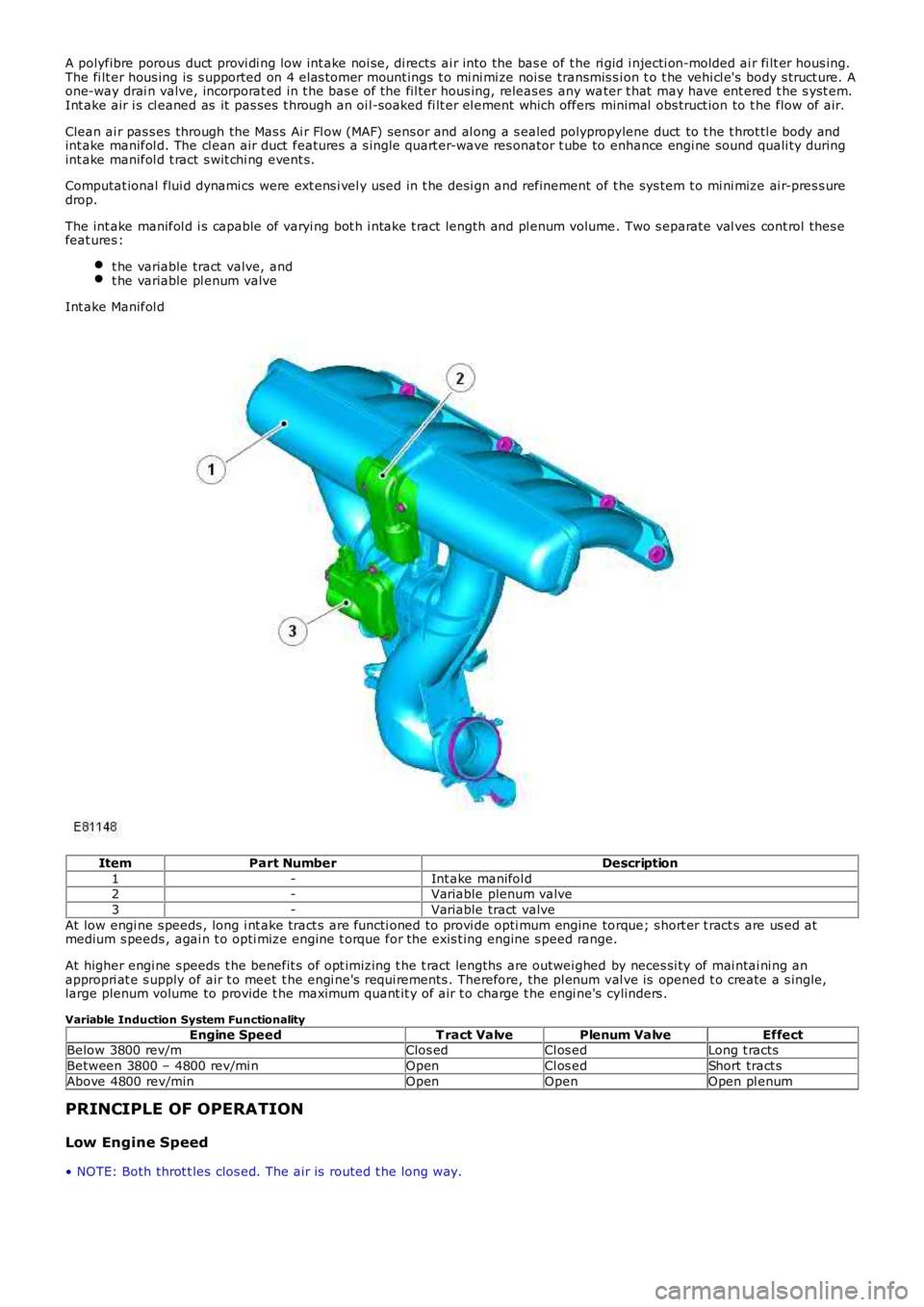
Int ake Manifol d
ItemPart NumberDescription
1-Int ake manifol d2-Variable plenum valve
3-Variable tract valve
At low engi ne s peeds , long i nt ake tract s are functi oned to provi de opti mum engine torque; s hort er t ract s are us ed atmedium s peeds , agai n t o opti mize engine t orque for the exis t ing engine s peed range.
At higher engi ne s peeds t he benefit s of opt imizing t he t ract lengths are outwei ghed by neces si ty of mai ntai ni ng anappropri at e s upply of air t o meet t he engi ne's requi rements . Therefore, the pl enum val ve is opened t o create a s ingle,large plenum volume to provide t he maximum quant it y of air t o charge t he engi ne's cylinders .
Variable Induction System Functionality
Engine SpeedT ract ValvePlenum ValveEffectBelow 3800 rev/mClos edCl os edLong t racts
Between 3800 – 4800 rev/mi nOpenCl os edShort tract s
Above 4800 rev/minOpenOpenOpen pl enum
PRINCIPLE OF OPERATION
Low Engine Speed
• NOTE: Both throt t les clos ed. The ai r is routed t he long way.
Page 1213 of 3229
The inject ors recei ve a fus ed bat tery vol tage s upply via the main relay. The ECM operates t he i nject ors by groundi ngs olenoi d valves in the injector. W hen t he ground is appl ied t he s olenoi d valve operat es and the injector s prays pres s uri zedfuel from the fuel rail i nt o t he cyl inder int ake ports . The amount of fuel injected and the t iming of t he inject ion peri od iscont rol led by t he ECM us ing dat a from other s ens ors .
The ECM can monit or the injector operat ion by moni toring t he ground l ine from the i njector. Each i njector can be diagnosedby t he ECM and faul t codes s t ored. The codes can be read us ing a Land Rover approved diagnos t ic s ys tem.
Variable Intake System (VIS)
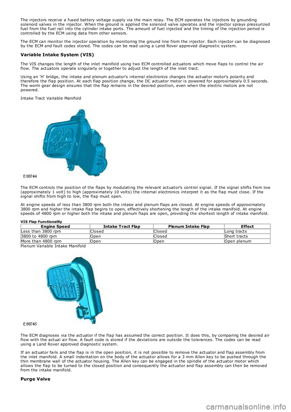
The VIS changes the length of t he inl et manifol d us ing t wo ECM controll ed act uators which move flaps t o cont rol t he airfl ow. The act uators operate s i ngul arly or t oget her to adjust t he l engt h of the inlet t ract.
Us ing an 'H' bridge, the intake and pl enum act uator's i nt ernal electroni cs changes the act uat or motor's polarit y andt herefore the flap pos it ion. At each fl ap pos i ti on change, the DC act uator mot or i s powered for approxi matel y 0.5 seconds .The worm gear des ign ens ures t hat the flap remains in t he desi red pos it ion, even when the el ect ri c mot ors are notpowered.
Int ake Tract Variabl e Manifol d
The ECM controls t he posi ti on of the flaps by modul at ing the relevant act uat or's cont rol s ignal. If the s ignal s hi ft s from low(approxi mately 1 volt ) to hi gh (approxi matel y 10 volt s) t he i nt ernal electroni cs interpret i t as the flap must cl os e. If thes ignal shi ft s from hi gh to low, t he fl ap mus t open.
At engi ne s peeds of l es s t han 3800 rpm both the i ntake and plenum flaps are clos ed. At engine s peeds of approxi matel y3800 rpm and higher the i ntake flap begins t o open, effecti vel y s hort eni ng the length of t he int ake manifol d. At engi nes peeds of 4800 rpm or higher bot h t he int ake and plenum flaps are open, providi ng the short es t length of i ntake manifold.
VIS Flap Functionality
Engine SpeedIntake T ract FlapPlenum Intake FlapEffectLess than 3800 rpmClos edClos edLong tract s
3800 t o 4800 rpmOpenClos edShort t racts
More than 4800 rpmOpenOpenOpen plenumPlenum Variable Int ake Mani fold
The ECM di agnos es vi a t he act uator i f the flap has as s umed the correct pos i ti on. It does this , by compari ng the des ired airfl ow wi th the act ual air flow. A fault code is st ored i f the deviat ions are outs ide t he t olerances. The codes can be readus ing a Land Rover approved di agnos ti c s ys t em.
If an act uat or fai ls and t he flap i s in the open pos it ion, it i s not pos s ible to remove t he act uator and flap as sembl y fromt he inlet mani fold. A smal l indentat ion on t he body of the actuat or al lows for a 3 mm Al len key t o be pus hed through t het hi n membrane wall of the act uat or hous ing. The All en key can be engaged i n t he spi ndl e of t he act uat or mot or whi chall ows the flap to be turned to the clos ed pos it ion and cons equent ly the actuat or and flap as s embly can t hen be removedfrom the i ntake manifold.
Purge Valve
Page 1395 of 3229
no s afet y margi n is required to counter expans i on. The i dl er wheel s for s ingl e and doubl e s ynchronizat ion have no cones .An i nner ring on t he s ynchroni zer unit performs thi s functi on ins tead.
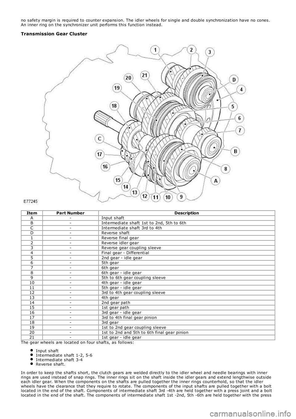
Transmission Gear Cluster
ItemPart NumberDescriptionA-Input s haft
B-Int ermedi at e s haft 1s t t o 2nd, 5t h t o 6th
C-Int ermedi at e s haft 3rd t o 4thD-Reverse s haft
1-Reverse fi nal gear
2-Reverse idler gear3-Reverse gear coupl ing s l eeve
4-Final gear - Di fferenti al
5-2nd gear - i dle gear6-5th gear
7-6th gear
8-6th gear - i dl e gear9-5th to 6t h gear coupli ng s leeve
10-4th gear - i dl e gear
11-5th gear - i dl e gear12-3rd to 4t h gear coupli ng s leeve
13-4th gear
14-2nd gear pat h15-1st gear path
16-3rd gear - i dl e gear
17-3rd to 4t h final gear pini on18-3rd gear
19-1st to 2nd gear coupl ing s leeve
20-1st to 2nd and 5t h t o 6t h fi nal gear pinion21-1st gear - i dl e gear
The gear wheels are l ocat ed on four s haft s, as foll ows:
Input s haftInt ermedi at e s haft 1-2, 5-6Int ermedi at e s haft 3-4Revers e s haft.
In order to keep the s haft s s hort , the clut ch gears are welded direct ly to t he i dl er wheel and needle beari ngs wit h innerri ngs are us ed i ns t ead of snap rings . The inner ri ngs s i t on the shaft ins ide t he idl er gears and ext end lengthwi se out s ideeach idler gear. W hen the component s on t he s hafts are pull ed t oget her t he i nner rings count erhold, s o t hat t he idl erwheels have t he cl earance that t hey requi re to rot at e. The components of t he i nput shaft s are pul led t oget her wit h a boltlocated i n t he end of the shaft . Component s of int ermediat e s haft 3rd -4t h are hel d t oget her wit h a pres s joint and a bol tlocated i n t he end of the shaft . The component s of intermediat e s haft 1st -2nd, 5t h -6th are held together wi th the pres s
Page 1962 of 3229
Publi s hed: 11-May-2011
Module Communications Network - Communications Network
Des cript ion and Operat ion
OVERVIEW
A number of different t ypes of communicati on network are incorporated into the vehicle wiring harnes s es for t het ransmis s ion of commands and informat ion between control modul es. The confi gurati on ins tal led on a parti cul ar vehicl edepends on t he model and equi pment level .
The communicati on net works avail abl e on t he vehi cl e are:
Local Int erconnect Network (LIN) busMedium speed Controll er Area Network (CAN) busHigh speed CAN busMedia O rient ated Sys tem Trans port (MO ST) ring
BusBaud Rate
LIN bus9.6 kbit s /s
Medium s peed CAN bus125 kbi ts /sHi gh Speed CAN bus500 kbi ts /s
MOST ring24 Mbit s/s
LOCAL INTERCONNECT NETWORK BUS
The Local Int erconnect Network (LIN) bus is a low s peed broadcas t net work that employs mas ter and s lave component s .The mas ter component t rans mit s a mess age along a si ngle wi re to the s lave component s i dent ifyi ng which s lave i s t ores pond. The mes s age has a header (s lave ident ifi er) and an empt y data fi eld. The identi fi ed s lave component fi ll s thedata fiel d wi th t he relevant i nformat ion and ret urns a mes s age to the mast er component along t he s ame wire.
CONTROLLER AREA NETWORK BUS
The Control ler Area Network (CAN) bus i s a high speed broadcast net work where cont rol modules aut omat icall y t rans mitinformat ion every few micros econds . Informati on is broadcas t down a pair of t wis t ed wires, known as 'CAN high' and 'CANlow'. Informat ion i s transmit ted on t he CAN bus as a vol tage di fference bet ween t he 2 wi res .
Two CAN bus net works are used on the vehicle; medi um s peed and high s peed, wi th the Cent ral Juncti on Box (CJB) acti ngas a gat eway bet ween t he 2 networks . The t abl e below shows t he wi re colors us ed on both net works .
Netw orkHighLow
Medium SpeedGrey and orangeViol et and orange
Hi gh SpeedW hit e and bl ueW hi te
MEDIA ORIENTATED SYSTEM TRANSPORT (MOST) RING
The Media O rient ated Sys tem Trans port (MO ST) ring us es fiber opt ic cables t o t rans port data and audio s ignal s around t heinformat ion and ent ertai nment sys tem. The fiber opti c cabl es are arranged in a ri ng, wit h each uni t on t he ri ng havi ng a'MOST in' and 'MOST out ' connect ion.
The MOST ring i s a s ynchronous net work. A t imi ng mas ter s uppl ies t he clock and all ot her component s on t he ri ngs ynchronize t heir operat ion t o t hi s clock. The t iming mas t er for the MOST ri ng is the i ntegrat ed cont rol module.
W hen handli ng MOST fiber opt ic cables t he fol lowi ng precaut ions s houl d be obs erved:
Aft er dis connect ion of any cables careful ly i nst all appropri ate dus t caps to protect the mati ng faces of theconnectors from damage and contami nat ion.Avoi d i nt roducing bends of les s t han 25 mm (0.98 inches ) radi us or ki nks int o the fiber opti c cabl e duri ng s ervice orrepair. Tight bends or kinks could i mpair operat ion, caus e immediate s ys t em failure, or future s ys t em fail ure.Avoi d exces s ive force, st rai n or s tress on the fibers or connect ors es peci ally permanent st res s after rei nst all at ion.
Ring Break Diag nostics
Incorporat ed i nt o t he Auxili ary Junct ion Box (AJB) is a Ri ng Break Di agnos ti cs (RBD) l ink. The RBD li nk hous es a copper linkwhich when removed init iat es the ri ng break diagnost ics mode. The ri ng break di agnosti cs mode allows the t echni ci an tolocate an opt ical fi ber break in t he MOST ring. To i nit iate the ring break diagnos t ics mode, carry out t he fol lowi ng proces s :
Connect t he Land Rover approved di agnos ti c s yst em.Ensure t he vehi cl e is in power mode 4 or great er.Remove the RBD li nk for t he length of ti me s peci fi ed by the Land Rover approved di agnos ti c s ys t em.Replace the RBD li nk.
Aft er approxi matel y 30 s econds a Di agnos t ic Trouble Code (DTC) wi ll be logged i n the Int egrated Cont rol Modul e,identi fyi ng the l ocat ion of t he faul t. The DTC can be read and int errogat ed usi ng t he Land Rover approved di agnos ti cs ys t em.
CONTROL DIAGRAM - LIN BUS (SHEET 1 OF 2)
• NOTE: O = LIN bus
Page 2015 of 3229
glue l ined heat s hrink s l eeve s o t hat the wiri ng harnes s ins ulat ion becomes damaged.
Two s izes of heat shrink s leeving are s uppl ied i n t he wiring harnes s repai r ki t. Each heat shrink s leeve cont ains a seal antglue. Thes e must be us ed when connect ing wi ri ng harness (s) or el ect ri cal connector termi nal (s ) at all t imes . The s mall erdiamet er heat s hri nk sl eeve is t o be us ed wi th the red and blue but t spl ice connectors and t he larger diamet er sl eeve wit ht he yel low but t s pl ice connect ors .
For eas e and s peed, s ome of t he pre-terminat ed wiring harnes s (s ) may al ready have the ins ul ati on part ly s t ripped at t hes plice end. If t he repai r requires ins ul ati on to be s tripped from the cable, refer to the Relat ions hip Table for the correctlength of ins ul ati on to be s tripped.
The Pre-Termi nat ed W i ri ng Harnes s(s ) il lus trati on shows t he elect rical connector t ermi nal t ype, t he part number of thepre-terminat ed wiring harnes s and t he let ter of t he ext ractor t ip which mus t be us ed to ext ract t he elect rical connect ort ermi nal from the connect or hous ing. Addi ti onal ly, t hos e el ect ri cal connector t ermi nal (s ) which are gold are i dent ified, allothers are t herefore, ti nned and not gold.
W i ri ng Harnes s Cabl e Ident ificati on Sleeves
A s electi on of col ored s leeves are cont ai ned in the wi ri ng harness repair kit for maint ai ning t he wi ring harnes s cableidenti fi cat ion on the pre-t ermi nat ed wi ri ng harness . Place t he correct col ored s l eeve(s ) over the pre-t ermi nat ed wi ri ngharnes s ins ulati on as near to the el ect ri cal connector as pos si ble wi th the main wi ri ng harness cable col or neares t t o t heelectrical connect or.
For example, i f the original wi ring harnes s cable color i s pink wi th a black t race put the pi nk wiring harnes s cableidenti fi cat ion s l eeve on the pre-t ermi nat ed wi ring harnes s firs t foll owed by a bl ack s l eeve, and s lide bot h along t he wi ri ngharnes s cabl e to the el ect ri cal connector t ermi nal.
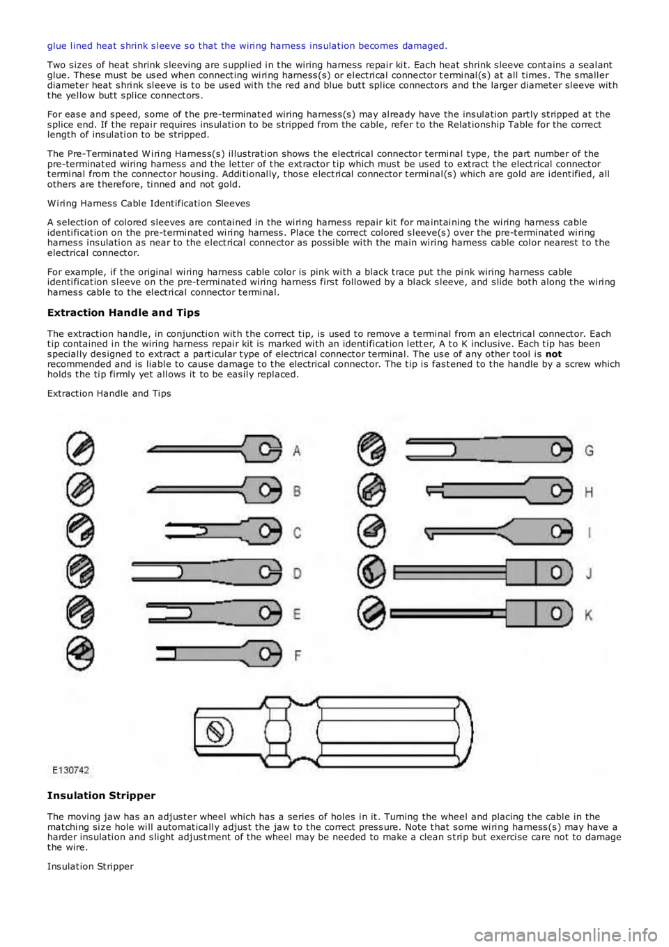
Extraction Handle and Tips
The extract ion handle, in conjuncti on wit h t he correct t ip, is used t o remove a t ermi nal from an electrical connect or. Eacht ip contained i n t he wiring harnes s repai r kit is marked wi th an identi fi cat ion l etter, A t o K inclus ive. Each t ip has beens pecial ly des igned t o extract a parti cul ar t ype of electrical connect or terminal. The us e of any other t ool i s notrecommended and is liabl e to caus e damage t o t he electrical connect or. The t ip i s fas t ened to t he handle by a screw whichholds t he ti p firmly yet all ows it to be eas il y repl aced.
Extract ion Handle and Ti ps
Insulation Stripper
The moving jaw has an adjus t er wheel which has a series of holes i n it . Turning the wheel and placing t he cabl e in themat chi ng si ze hole wi ll automat icall y adjus t the jaw t o t he correct pres s ure. Note that s ome wi ri ng harness (s ) may have aharder ins ulati on and s li ght adjus t ment of the wheel may be needed to make a clean st ri p but exerci se care not to damaget he wire.
Ins ulat ion St ri pper