sensor LEXUS LS430 2003 Factory Repair Manual
[x] Cancel search | Manufacturer: LEXUS, Model Year: 2003, Model line: LS430, Model: LEXUS LS430 2003Pages: 4500, PDF Size: 87.45 MB
Page 459 of 4500
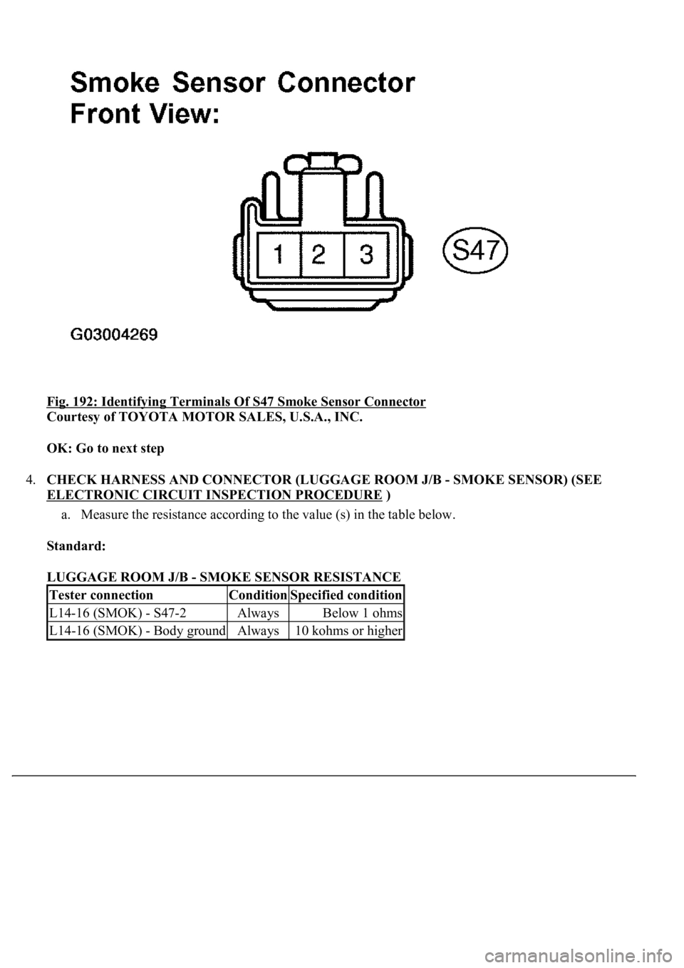
Fig. 192: Identifying Terminals Of S47 Smoke Sensor Connector
Courtesy of TOYOTA MOTOR SALES, U.S.A., INC.
OK: Go to next step
4.CHECK HARNESS AND CONNECTOR (LUGGAGE ROOM J/B - SMOKE SENSOR) (SEE
ELECTRONIC CIRCUIT INSPECTION PROCEDURE
)
a. Measure the resistance according to the value (s) in the table below.
Standard:
LUGGAGE ROOM J/B - SMOKE SENSOR RESISTANCE
Tester connectionConditionSpecified condition
L14-16 (SMOK) - S47-2AlwaysBelow 1 ohms
L14-16 (SMOK) - Body groundAlways10 kohms or higher
Page 461 of 4500
Fig. 193: Checking Harness And Connector (Luggage Room J/B -Smoke Sensor)
Courtesy of TOYOTA MOTOR SALES, U.S.A., INC.
NG: REPAIR OR REPLACE HARNESS OR CONNECTOR
OK: REPLACE LUGGAGE ROOM J/B ECU
CIRCUIT DESCRIPTION
The intelligent swing register is controlled by the A/C amplifier. It is activated by selecting FACE or BI-
LEVEL on the mode select switch and turning the swing register switch on.
WIRING DIAGRAM
Page 472 of 4500
a. The suspension control ECU operates the compressor & motor with the dryer and uses the solenoid
valves to control the vehicle height by analyzing the information based on the switches, sensors and
input signals.
b. Through the 4 height control sensors, the suspension control ECU detects the changes in the vehicle
height that results from the number of occupants or the amount of the load. Then, the suspension
control ECU controls the height control solenoid valves and the compressor & motor with the dryer
in order to automatically adjust the vehicle height to a constant (normal) level.
c. Furthermore, two vehicle heights can be selected by operating the height control switch: HI and
Normal.
d. In cases such as when the vehicle is jacked up, the auto leveling function is prohibited by turning
the ignition switch off.
If the vehicle is raised with its engine running, connect terminals OPB and CG of the DLC3 so the
vehicle height control is not carried out.
e. The absorber control switch selects the shock absorber damping force (normal or sport).
f. w/ Pre-collision safety system:
The suspension control ECU changes the stiffness of the suspension to the hardest setting by
receiving signals (collision unavoidable) from the cruise control ECU.
Function of Components
Page 474 of 4500
TROUBLE CODE (Go to step 7)
6.(SEE PROBLEM SYMPTOMS TABLE
)
7.(SEE DIAGNOSTIC TROUBLE CODE CHART
)
8.CIRCUIT INSPECTION (SEE DTC C1711 RIGHT FRONT HEIGHT CONTROL SENSOR
CIRCUIT, DTC C1712 LEFT FRONT HEIGHT CONTROL SENSOR CIRCUIT,DTC C1713
RIGHT REAR HEIGHT CONTROL SENSOR CIRCUIT, DTC C1714 LEFT REAR HEIGHT
CONTROL SENSOR CIRCUIT to TD TERMINAL CIRCUIT )
9.IDENTIFICATION OF PROBLEM
10.REPAIR
11.CONFIRMATION TEST
END
Page 476 of 4500
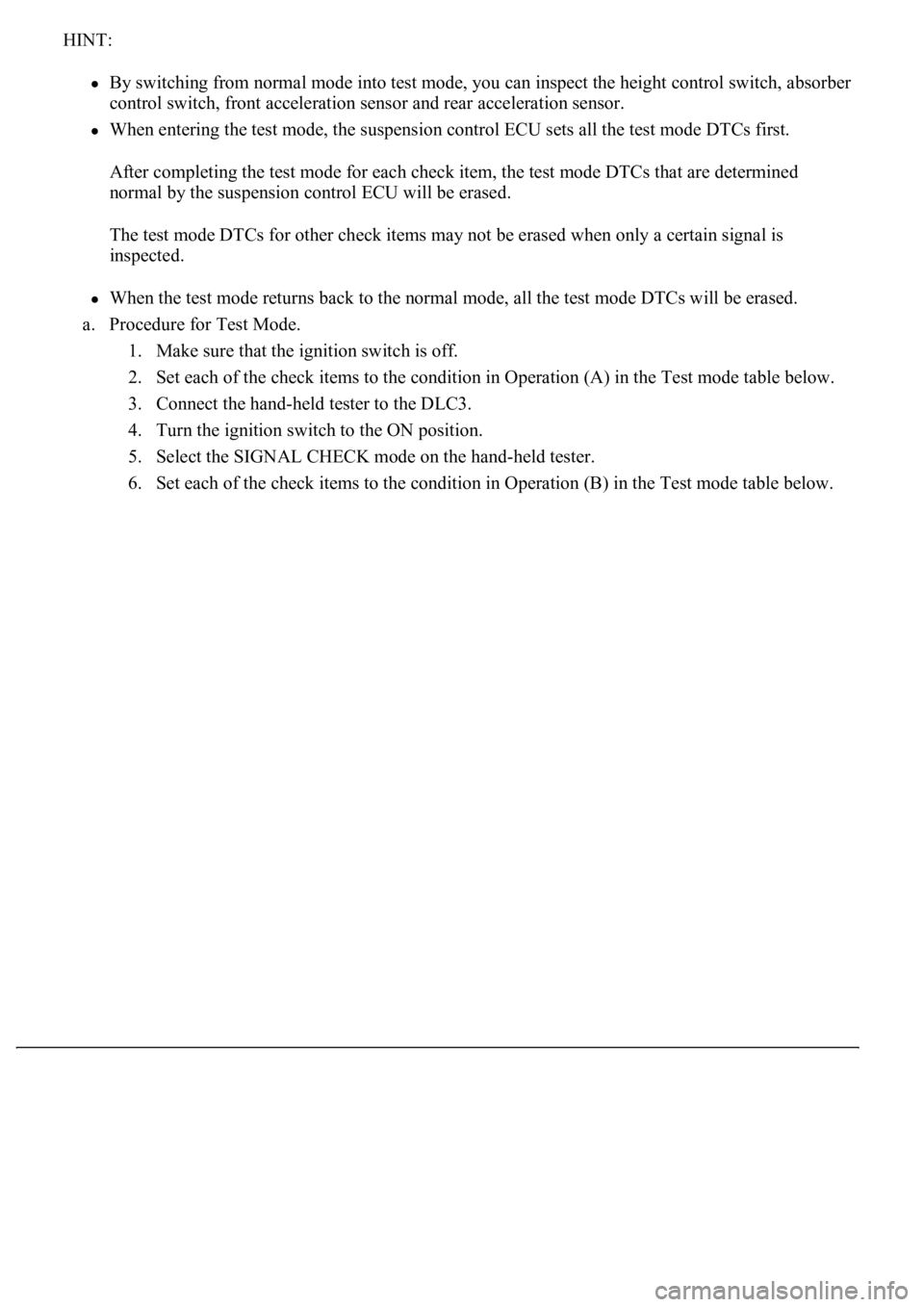
HINT:
By switching from normal mode into test mode, you can inspect the height control switch, absorber
control switch, front acceleration sensor and rear acceleration sensor.
When entering the test mode, the suspension control ECU sets all the test mode DTCs first.
After completing the test mode for each check item, the test mode DTCs that are determined
normal by the suspension control ECU will be erased.
The test mode DTCs for other check items may not be erased when only a certain signal is
inspected.
When the test mode returns back to the normal mode, all the test mode DTCs will be erased.
a. Procedure for Test Mode.
1. Make sure that the ignition switch is off.
2. Set each of the check items to the condition in Operation (A) in the Test mode table below.
3. Connect the hand-held tester to the DLC3.
4. Turn the ignition switch to the ON position.
5. Select the SIGNAL CHECK mode on the hand-held tester.
6. Set each of the check items to the condition in Operation (B) in the Test mode table below.
Page 477 of 4500
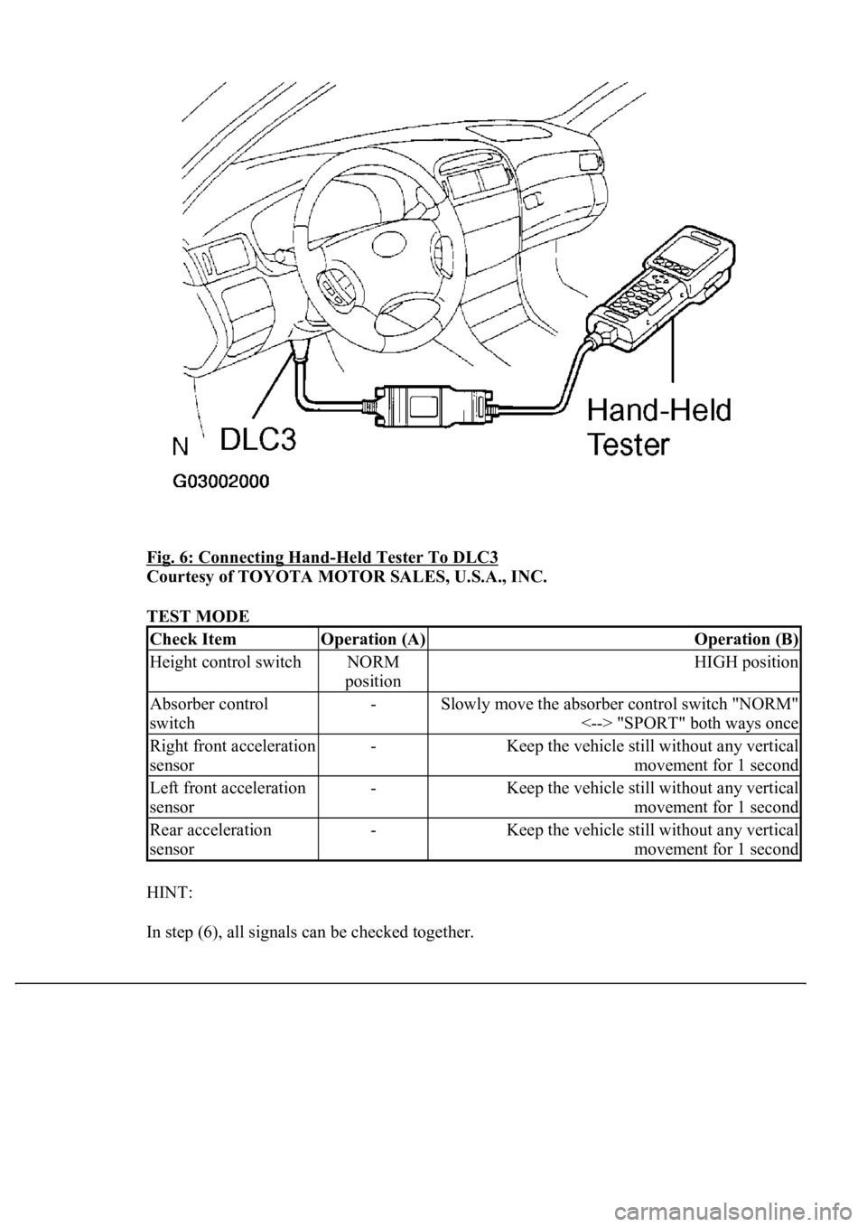
Fig. 6: Connecting Hand-Held Tester To DLC3
Courtesy of TOYOTA MOTOR SALES, U.S.A., INC.
TEST MODE
HINT:
In step (6), all signals can be checked together.
Check ItemOperation (A)Operation (B)
Height control switchNORM
positionHIGH position
Absorber control
switch-Slowly move the absorber control switch "NORM"
<--> "SPORT" both ways once
Right front acceleration
sensor-Keep the vehicle still without any vertical
movement for 1 second
Left front acceleration
sensor-Keep the vehicle still without any vertical
movement for 1 second
Rear acceleration
sensor-Keep the vehicle still without any vertical
movement for 1 second
Page 481 of 4500

RC (A20-6) -
GND (A20-4)Y-R - W-BAIR SUS relay
Engine idling, height control switch
from "NORM" to "HIGH" during
compressor operation
8 V or more
CANH (A20-7) -
CANL (A20-8)BR - YCAN communication
lineIG switch OFF54 to 67
ohms
SW1 (A20-9) -
GND (A20-4)O - W-BAbsorber control switch
input signalEngine idling, absorber control
switch "NORM" position10 to 14 V
SW1 (A20-9) -
GND (A20-4)O - W-BAbsorber control switch
input signalEngine idling, absorber control
switch "SPORT" position0 to 1.5 V
SIL (A20-13) -
GND (A20-4)W-G - W-
BDiagnosis tester
communication lineIG switch ONPulse
generation
TD (A20-14) -
GND (A20-4)L-B - W-BHeight control is not
operatingIG switch ON10 to 14 V
HSW (A20-15) -
GND (A20-4)LG-B - W-
BHeight control switch
input signalIG switch ON, height control
switch "NORM" position10 to 14 V
HSW (A20-15) -
GND (A20-4)LG-B - W-
BHeight control switch
input signalIG switch ON, height control
switch "HIGH" position0 to 1.5 V
SLFR (A20-16) -
GND (A20-4)G-W - W-
BHeight control solenoid
valve (FR)IG switch ONBelow 1 V
SLFR (A20-16) -
GND (A20-4)G-W - W-
BHeight control solenoid
valve (FR)Engine idling, height control switch
from "NORM" to "HIGH" or
reverse
8 V or more
SLFL (A20-17) -
GND (A20-4)R-W - W-
BHeight control solenoid
valve (FL)IG switch ONBelow 1 V
SLFL (A20-17) -
GND (A20-4)R-W - W-
BHeight control solenoid
valve (FL)Engine idling, height control switch
from "NORM" to "HIGH" or
reverse
8 V or more
SBL1 (A20-18) -
GND (A20-4)LG-R - W-
BHeight control sensor
power source (FL)IG switch ON4.5 to 5.5 V
VH (A20-19) -
GND (A20-4)P - W-BHeight control indicator
output signalIG switch ON, height control
switch "HIGH"0 to 1.5 V
SBR1 (A20-20) -
GND (A20-4)V-R - W-BHeight control indicator
output signalIG switch ON, height control
switch "NORM"10 to 14 V
SBR1 (A20-20) -
GND (A20-4)V-R - W-BHeight control sensor
power source (FR)IG switch ON4.5 to 5.5 V
SGR1 (A20-21) -
GND (A20-4)R-L - W-BHeight control sensor
ground (FR)AlwaysBelow 1
ohms
SGL1 (A20-22) -
GND (A20-4)LG-B - W-
BHeight control sensor
ground (FL)AlwaysBelow 1
ohms
FAR+ (A21-1) -
FAR- (A21-2)O - R-YSuspension control
actuator (FR)IG switch ONBelow 1
ohms
FBR+ (A21-3) -
FBR- (A21-4)R-G - L-GSuspension control
actuator (FR)IG switch ONBelow 1
ohms
FAL+ (A21-5) -
FAL- (A21-14)G-B - G-RSuspension control
actuator (FL)IG switch ONBelow 1
ohms
Page 482 of 4500

FBL+ (A21-6) -
FBL- (A21-16)G-W - G-
OSuspension control
actuator (FL)IG switch ONBelow 1
ohms
SLRL (A21-7) -
GND (A20-4)P-L - W-BHeight control solenoid
valve (RL)IG switch ONBelow 1 V
SLRL (A21-7) -
GND (A20-4)P-L - W-BHeight control solenoid
valve (RL)Engine idling, height control switch
from "NORM" to "HIGH" or
reverse
8 V or more
SLRR (A21-8) -
GND (A20-4)P - W-BHeight control solenoid
valve (RR)IG switch ONBelow 1 V
SLRR (A21-8) -
GND (A20-4)P - W-BHeight control solenoid
valve (RR)Engine idling, height control switch
from "NORM" to "HIGH" or
reverse
8 V or more
RM+ (A21-17) -
GND (A20-4)BR-Y - W-
BMotor lock (+)
Engine idling, height control switch
from "NORM" to "HIGH" during
compressor operation
Below 1 V
RM- (A21-18) -
GND (A20-4)BR-B - W-
BMotor lock (-)AlwaysBelow 1
ohms
SHR2 (A21-19) -
GND (A20-4)W - W-BHeight control sensor
(HID rear)IG switch ON0.5 to 4.5 V
SHFR (A21-20) -
GND (A20-4)B-W - W-
BHeight control sensor
(FR)IG switch ON0.5 to 4.5 V
SHFR (A21-20) -
GND (A20-4)B-W - W-
BHeight control sensor
(FR)Engine idling, height control switch
"NORM"Approx. 2.5
V
SHF2 (A21-21) -
GND (A20-4)V-G - W-BHeight control sensor
(HID front)IG switch ON0.5 to 4.5 V
SHFL (A21-22) -
GND (A20-4)L - W-BHeight control sensor
(FL)IG switch ON0.5 to 4.5 V
SHFL (A21-22) -
GND (A20-4)L - W-BHeight control sensor
(FL)Engine idling, height control switch
"NORM"Approx. 2.5
V
SBL3 (A21-23) -
GND (A20-4)B - W-BHeight control sensor
power source (HID)IG switch ON4.5 to 5.5 V
SGL3 (A21-24) -
GND (A20-4)V-Y - W-BHeight control sensor
ground (HID)AlwaysBelow 1
ohms
RAR+ (A22-2) -
RAR- (A22-3)Y - SBSuspension control
actuator (RR)IG switch ONBelow 1
ohms
RBR+ (A22-4) -
RBR- (A22-5)LG - PSuspension control
actuator (RR)IG switch ONBelow 1
ohms
RAL+ (A22-6) -
RAL- (A22-7)L - GSuspension control
actuator (RL)IG switch ONBelow 1
ohms
RBL+ (A22-8) -
RBL- (A22-9)O - BRSuspension control
actuator (RLIG switch ONBelow 1
ohms
SGR3 (A22-12) -
GND (A20-4)W - W-BAcceleration sensor
ground (rear)AlwaysBelow 1
ohms
SBR3 (A22-15) -
GND (A20-4)R - W-BAcceleration sensor
power source (rear)IG switch ON4.5 to 5.5 V
Page 483 of 4500
1.DIAGNOSIS SYSTEM
a. Inspect the battery voltage.
Battery voltage: 11 to 14 V
If the voltage is below 11 V, recharge the battery before proceeding.
b. Check DLC3.
The suspension control ECU uses the CAN system and ISO 9141-2 for communication. The
terminal arrangement of the DLC3 complies with SAE J1962 and matches the ISO 9141-2 format.
Verify the conditions listed in the table below:
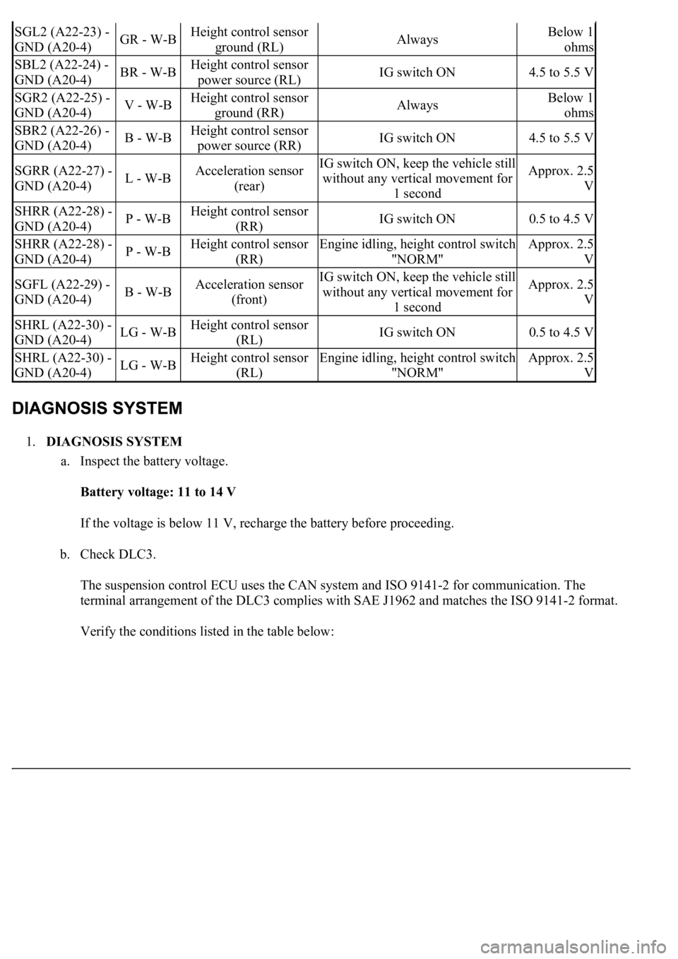
SGL2 (A22-23) -
GND (A20-4)GR - W-BHeight control sensor
ground (RL)AlwaysBelow 1
ohms
SBL2 (A22-24) -
GND (A20-4)BR - W-BHeight control sensor
power source (RL)IG switch ON4.5 to 5.5 V
SGR2 (A22-25) -
GND (A20-4)V - W-BHeight control sensor
ground (RR)AlwaysBelow 1
ohms
SBR2 (A22-26) -
GND (A20-4)B - W-BHeight control sensor
power source (RR)IG switch ON4.5 to 5.5 V
SGRR (A22-27) -
GND (A20-4)L - W-BAcceleration sensor
(rear)IG switch ON, keep the vehicle still
without any vertical movement for
1 secondApprox. 2.5
V
SHRR (A22-28) -
GND (A20-4)P - W-BHeight control sensor
(RR)IG switch ON0.5 to 4.5 V
SHRR (A22-28) -
GND (A20-4)P - W-BHeight control sensor
(RR)Engine idling, height control switch
"NORM"Approx. 2.5
V
SGFL (A22-29) -
GND (A20-4)B - W-BAcceleration sensor
(front)IG switch ON, keep the vehicle still
without any vertical movement for
1 secondApprox. 2.5
V
SHRL (A22-30) -
GND (A20-4)LG - W-BHeight control sensor
(RL)IG switch ON0.5 to 4.5 V
SHRL (A22-30) -
GND (A20-4)LG - W-BHeight control sensor
(RL)Engine idling, height control switch
"NORM"Approx. 2.5
V
Page 486 of 4500
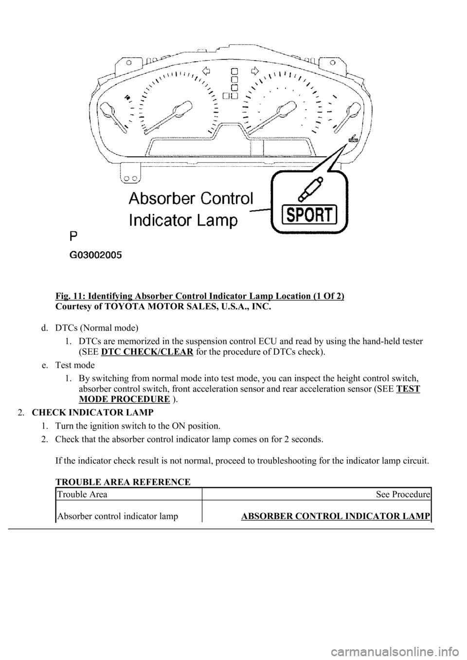
Fig. 11: Identifying Absorber Control Indicator Lamp Location (1 Of 2)
Courtesy of TOYOTA MOTOR SALES, U.S.A., INC.
d. DTCs (Normal mode)
1. DTCs are memorized in the suspension control ECU and read by using the hand-held tester
(SEE DTC CHECK/CLEAR
for the procedure of DTCs check).
e. Test mode
1. By switching from normal mode into test mode, you can inspect the height control switch,
absorber control switch, front acceleration sensor and rear acceleration sensor (SEE TEST
MODE PROCEDURE ).
2.CHECK INDICATOR LAMP
1. Turn the ignition switch to the ON position.
2. Check that the absorber control indicator lamp comes on for 2 seconds.
If the indicator check result is not normal, proceed to troubleshooting for the indicator lamp circuit.
TROUBLE AREA REFERENCE
Trouble AreaSee Procedure
Absorber control indicator lamp ABSORBER CONTROL INDICATOR LAMP