LEXUS LS430 2003 Factory Repair Manual
Manufacturer: LEXUS, Model Year: 2003,
Model line: LS430,
Model: LEXUS LS430 2003
Pages: 4500, PDF Size: 87.45 MB
LEXUS LS430 2003 Factory Repair Manual
LS430 2003
LEXUS
LEXUS
https://www.carmanualsonline.info/img/36/57050/w960_57050-0.png
LEXUS LS430 2003 Factory Repair Manual
Trending: c1336, brake light, headrest, Door lock actuator, bulb, fuel, differential
Page 2391 of 4500
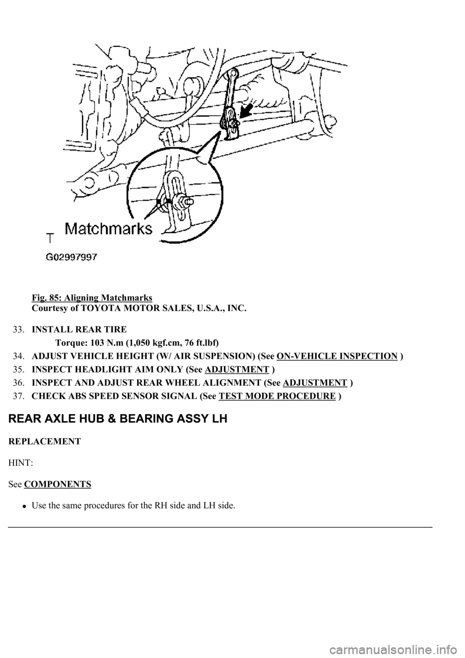
Fig. 85: Aligning Matchmarks
Courtesy of TOYOTA MOTOR SALES, U.S.A., INC.
33.INSTALL REAR TIRE
Torque: 103 N.m (1,050 kgf.cm, 76 ft.lbf)
34.ADJUST VEHICLE HEIGHT (W/ AIR SUSPENSION) (See ON
-VEHICLE INSPECTION )
35.INSPECT HEADLIGHT AIM ONLY (See ADJUSTMENT
)
36.INSPECT AND ADJUST REAR WHEEL ALIGNMENT (See ADJUSTMENT
)
37.CHECK ABS SPEED SENSOR SIGNAL (See TEST MODE PROCEDURE
)
REPLACEMENT
HINT:
See COMPONENTS
<00380056004800030057004b00480003005600440050004800030053005500520046004800470058005500480056000300490052005500030057004b004800030035002b00030056004c0047004800030044005100470003002f002b00030056004c004700
4800110003[
Page 2392 of 4500
The procedures listed below are for the LH side.
1.REMOVE REAR TIRE
2.SEPARATE HEIGHT CONTROL SENSOR LINK SUB-ASSY REAR (See REPLACEMENT
)
3.REMOVE REAR AXLE SHAFT NUT (See REPLACEMENT
)
4.REMOVE REAR DISC BRAKE CALIPER ASSY LH (See REPLACEMENT
)
5.REMOVE REAR DISC
6.SEPARATE SPEED SENSOR REAR LH (See REPLACEMENT
)
7.REMOVE PARKING BRAKE SHOE RETURN TENSION SPRING (See step 5 on OVERHAUL
)
SST 09703-30010
8.REMOVE PARKING BRAKE SHOE ADJUSTING SCREW SET (See OVERHAUL
)
9.REMOVE PARKING BRAKE SHOE ASSY LH NO. 1 (See step 6 on OVERHAUL
)
SST 09718-00010
10.REMOVE PARKING BRAKE SHOE ASSY LH NO. 2 (See step 7 on OVERHAUL
)
SST 09718-00010
11.REMOVE PARKING BRAKE SHOE LEVER SUB-ASSY LH (See step 10 on OVERHAUL
)
12.REMOVE PARKING BRAKE CABLE ASSY NO. 3 (See step 11 on REPLACEMENT
)
13.REMOVE PARKING BRAKE ANCHOR BLOCK SUB-ASSY (See step 13 on OVERHAUL
)
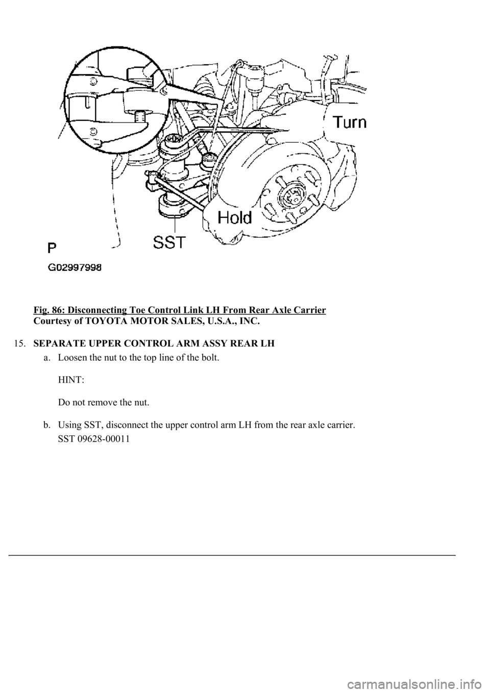
14.SEPARATE TOE CONTROL LINK SUB-ASSY LH
a. Remove the nut.
b. Using SST, disconnect the toe control link LH from the rear axle carrier.
SST 09628-00011
Page 2393 of 4500
Fig. 86: Disconnecting Toe Control Link LH From Rear Axle Carrier
Courtesy of TOYOTA MOTOR SALES, U.S.A., INC.
15.SEPARATE UPPER CONTROL ARM ASSY REAR LH
a. Loosen the nut to the top line of the bolt.
HINT:
Do not remove the nut.
b. Using SST, disconnect the upper control arm LH from the rear axle carrier.
SST 09628-00011
Page 2394 of 4500
Fig. 87: Disconnecting Upper Control Arm LH From Rear Axle Carrier
Courtesy of TOYOTA MOTOR SALES, U.S.A., INC.
16.SEPARATE SHOCK ABSORBER ASSY REAR LH
a. Remove the nut and disconnect the shock absorber ass
y rear LH from the axle carrier.
Page 2395 of 4500
Fig. 88: Removing Shock Absorber Assy Rear LH Nut
Courtesy of TOYOTA MOTOR SALES, U.S.A., INC.
17.SEPARATE REAR SUSPENSION ARM ASSY NO. 1 LH
a. Remove the nut.
b. Using SST, disconnect the suspension arm assy No. 1 from the rear axle carrier.
SST 09628-0001 1
Page 2396 of 4500
<0029004c004a00110003001b001c001d00030027004c00560046005200510051004800460057004c0051004a00030036005800560053004800510056004c0052005100030024005500500003002400560056005c0003003100520011000300140003002900
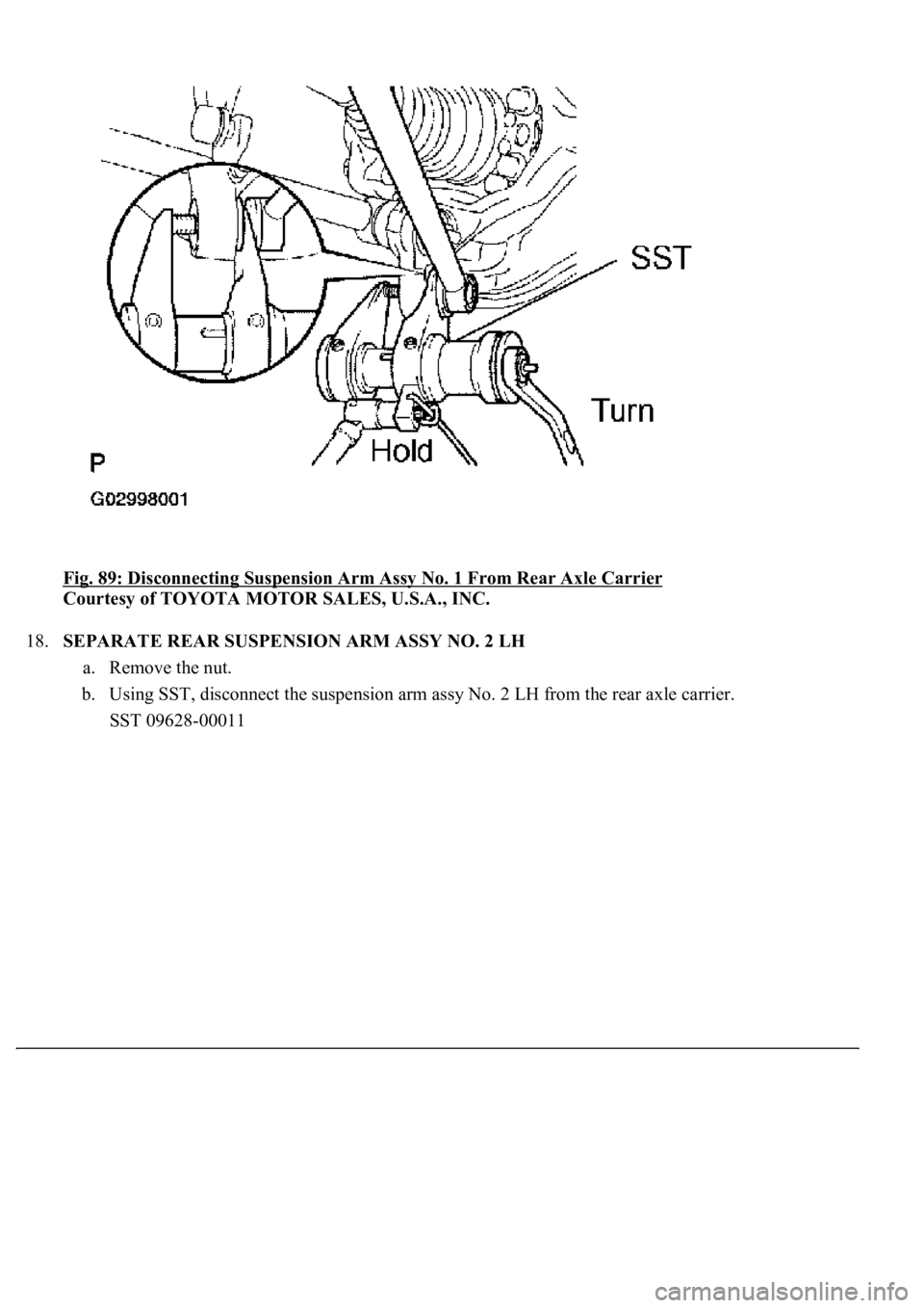
55005200500003003500480044005500030024005b004f0048[ Carrier
Courtesy of TOYOTA MOTOR SALES, U.S.A., INC.
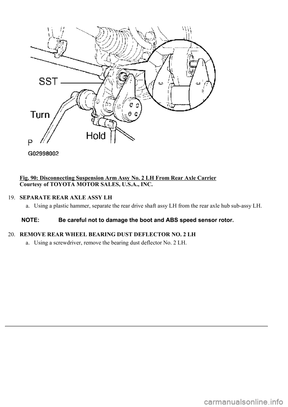
18.SEPARATE REAR SUSPENSION ARM ASSY NO. 2 LH
a. Remove the nut.
b. Using SST, disconnect the suspension arm assy No. 2 LH from the rear axle carrier.
SST 09628-00011
Page 2397 of 4500
<0029004c004a00110003001c0013001d00030027004c00560046005200510051004800460057004c0051004a00030036005800560053004800510056004c0052005100030024005500500003002400560056005c0003003100520011000300150003002f00
2b000300290055005200500003003500480044005500030024[xle Carrier
Courtesy of TOYOTA MOTOR SALES, U.S.A., INC.
19.SEPARATE REAR AXLE ASSY LH
a. Using a plastic hammer, separate the rear drive shaft assy LH from the rear axle hub sub-assy LH.
20.REMOVE REAR WHEEL BEARING DUST DEFLECTOR NO. 2 LH
a. Usin
g a screwdriver, remove the bearing dust deflector No. 2 LH.
Page 2398 of 4500
Fig. 91: Removing Bearing Dust Deflector No. 2 LH
Courtesy of TOYOTA MOTOR SALES, U.S.A., INC.
21.REMOVE REAR AXLE HUB & BEARING ASSY LH
a. Remove the 4 bolts and axle hub & bearing assy LH.
Page 2399 of 4500
Fig. 92: Removing Rear Axle Hub & Bearing Assy LH Bolts
Courtesy of TOYOTA MOTOR SALES, U.S.A., INC.
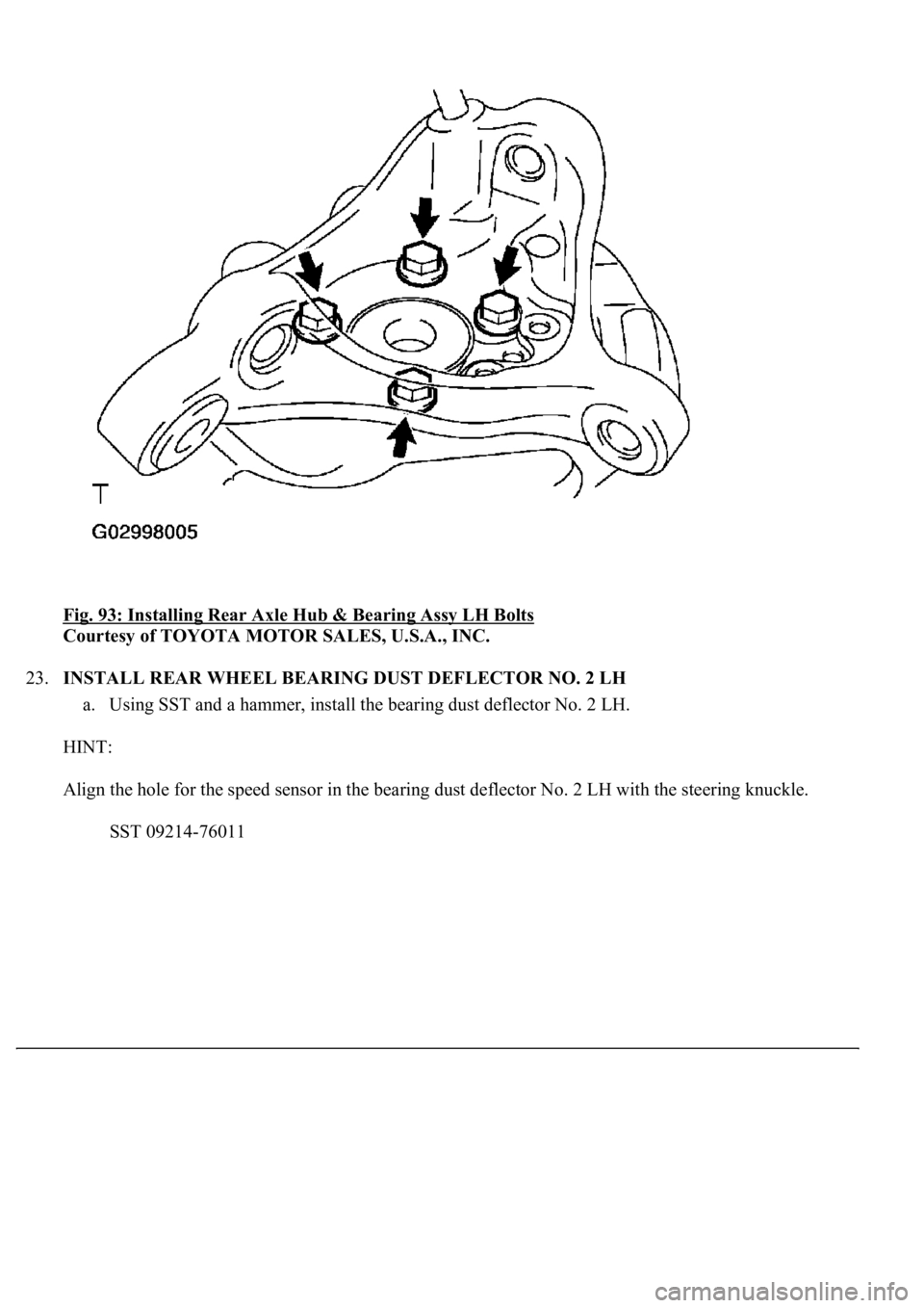
22.INSTALL REAR AXLE HUB & BEARING ASSY LH
a. Install the axle hub & bearing assy LH with the 4 bolts.
Torque: 65 N.m (660 kgf.cm, 48 ft.lbf)
Page 2400 of 4500
Fig. 93: Installing Rear Axle Hub & Bearing Assy LH Bolts
Courtesy of TOYOTA MOTOR SALES, U.S.A., INC.
23.INSTALL REAR WHEEL BEARING DUST DEFLECTOR NO. 2 LH
a. Using SST and a hammer, install the bearing dust deflector No. 2 LH.
HINT:
Align the hole for the speed sensor in the bearing dust deflector No. 2 LH with the steering knuckle.
SST 09214-76011
Trending: B2620, low oil pressure, USB port, vacuum switching valve, garage door opener, B2419, oil temperature
