LEXUS LS430 2003 Factory Repair Manual
Manufacturer: LEXUS, Model Year: 2003,
Model line: LS430,
Model: LEXUS LS430 2003
Pages: 4500, PDF Size: 87.45 MB
LEXUS LS430 2003 Factory Repair Manual
LS430 2003
LEXUS
LEXUS
https://www.carmanualsonline.info/img/36/57050/w960_57050-0.png
LEXUS LS430 2003 Factory Repair Manual
Trending: wipers, wheel, alarm, change time, headlamp, timing belt, spark plugs replace
Page 2471 of 4500
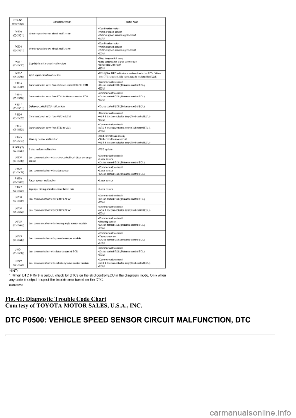
Fig. 41: Diagnostic Trouble Code Chart
Courtesy of TOYOTA MOTOR SALES, U.S.A., INC.
Page 2472 of 4500
CIRCUIT DESCRIPTION
See CIRCUIT DESCRIPTION
.
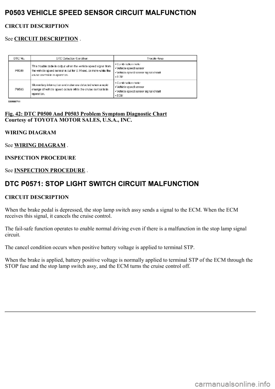
Fig. 42: DTC P0500 And P0503 Problem Symptom Diagnostic Chart
Courtesy of TOYOTA MOTOR SALES, U.S.A., INC.
WIRING DIAGRAM
See WIRING DIAGRAM
.
INSPECTION PROCEDURE
See INSPECTION PROCEDURE
.
CIRCUIT DESCRIPTION
When the brake pedal is depressed, the stop lamp switch assy sends a signal to the ECM. When the ECM
receives this signal, it cancels the cruise control.
The fail-safe function operates to enable normal driving even if there is a malfunction in the stop lamp signal
circuit.
The cancel condition occurs when positive battery voltage is applied to terminal STP.
When the brake is applied, battery positive voltage is normally applied to terminal STP of the ECM through the
STOP fuse and the stop lamp switch ass
y, and the ECM turns the cruise control off.
Page 2473 of 4500
Fig. 43: DTC P0571 Problem Symptom Diagnostic Chart
Courtesy of TOYOTA MOTOR SALES, U.S.A., INC.
WIRING DIAGRAM
Page 2474 of 4500
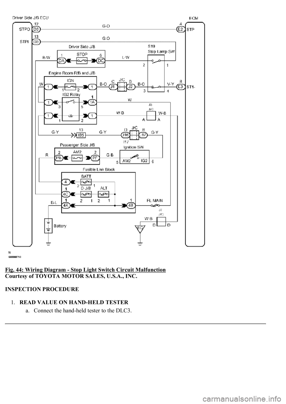
Fig. 44: Wiring Diagram - Stop Light Switch Circuit Malfunction
Courtesy of TOYOTA MOTOR SALES, U.S.A., INC.
INSPECTION PROCEDURE
1.READ VALUE ON HAND-HELD TESTER
a. Connect the han
d-held tester to the DLC3.
Page 2475 of 4500
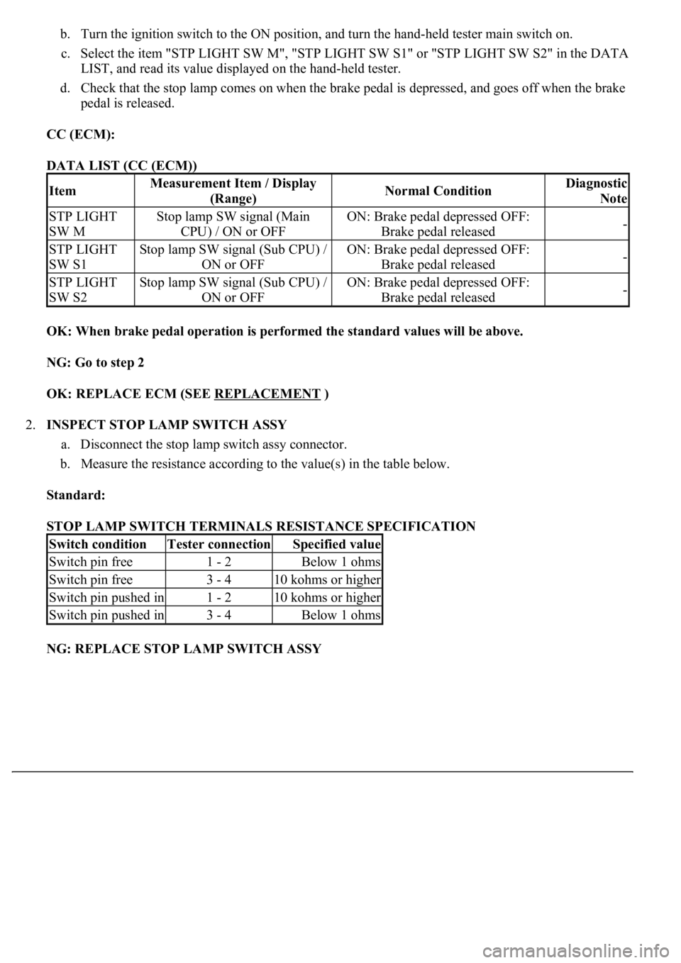
b. Turn the ignition switch to the ON position, and turn the hand-held tester main switch on.
c. Select the item "STP LIGHT SW M", "STP LIGHT SW S1" or "STP LIGHT SW S2" in the DATA
LIST, and read its value displayed on the hand-held tester.
d. Check that the stop lamp comes on when the brake pedal is depressed, and goes off when the brake
pedal is released.
CC (ECM):
DATA LIST (CC (ECM))
OK: When brake pedal operation is performed the standard values will be above.
NG: Go to step 2
OK: REPLACE ECM (SEE REPLACEMENT
)
2.INSPECT STOP LAMP SWITCH ASSY
a. Disconnect the stop lamp switch assy connector.
b. Measure the resistance according to the value(s) in the table below.
Standard:
STOP LAMP SWITCH TERMINALS RESISTANCE SPECIFICATION
NG: REPLACE STOP LAMP SWITCH ASSY
ItemMeasurement Item / Display
(Range)Normal ConditionDiagnostic
Note
STP LIGHT
SW MStop lamp SW signal (Main
CPU) / ON or OFFON: Brake pedal depressed OFF:
Brake pedal released-
STP LIGHT
SW S1Stop lamp SW signal (Sub CPU) /
ON or OFFON: Brake pedal depressed OFF:
Brake pedal released-
STP LIGHT
SW S2Stop lamp SW signal (Sub CPU) /
ON or OFFON: Brake pedal depressed OFF:
Brake pedal released-
Switch conditionTester connectionSpecified value
Switch pin free1 - 2Below 1 ohms
Switch pin free3 - 410 kohms or higher
Switch pin pushed in1 - 210 kohms or higher
Switch pin pushed in3 - 4Below 1 ohms
Page 2476 of 4500
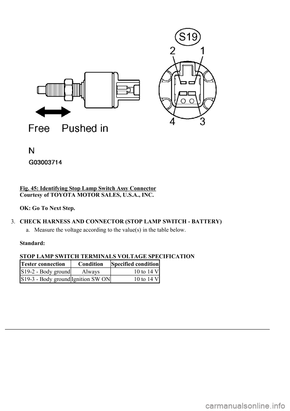
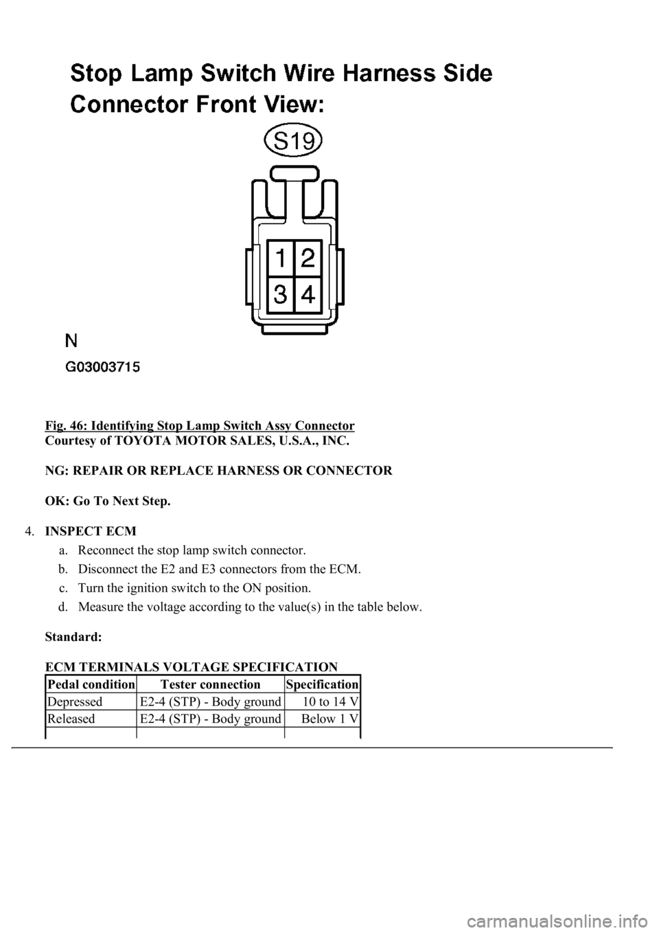
Fig. 45: Identifying Stop Lamp Switch Assy Connector
Courtesy of TOYOTA MOTOR SALES, U.S.A., INC.
OK: Go To Next Step.
3.CHECK HARNESS AND CONNECTOR (STOP LAMP SWITCH - BATTERY)
a. Measure the voltage according to the value(s) in the table below.
Standard:
STOP LAMP SWITCH TERMINALS VOLTAGE SPECIFICATION
Tester connectionConditionSpecified condition
S19-2 - Body groundAlways10 to 14 V
S19-3 - Body groundIgnition SW ON10 to 14 V
Page 2477 of 4500
Fig. 46: Identifying Stop Lamp Switch Assy Connector
Courtesy of TOYOTA MOTOR SALES, U.S.A., INC.
NG: REPAIR OR REPLACE HARNESS OR CONNECTOR
OK: Go To Next Step.
4.INSPECT ECM
a. Reconnect the stop lamp switch connector.
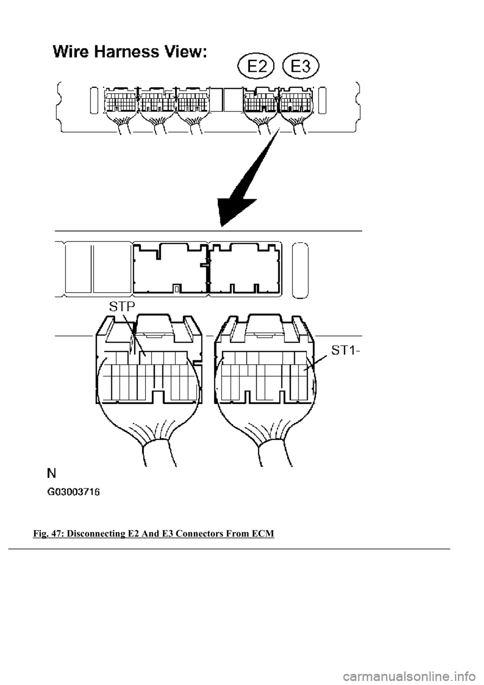
b. Disconnect the E2 and E3 connectors from the ECM.
c. Turn the ignition switch to the ON position.
d. Measure the voltage according to the value(s) in the table below.
Standard:
ECM TERMINALS VOLTAGE SPECIFICATION
Pedal conditionTester connectionSpecification
DepressedE2-4 (STP) - Body ground10 to 14 V
ReleasedE2-4 (STP) - Body groundBelow 1 V
Page 2478 of 4500
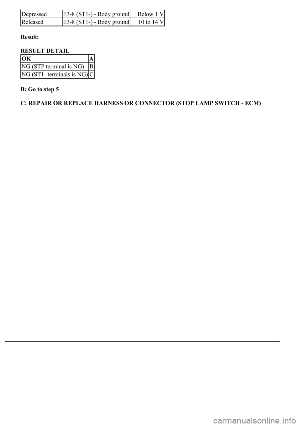
Result:
RESULT DETAIL
B: Go to step 5
C: REPAIR OR REPLACE HARNESS OR CONNECTOR (STOP LAMP SWITCH - ECM)
DepressedE3-8 (ST1-) - Body groundBelow 1 V
ReleasedE3-8 (ST1-) - Body ground10 to 14 V
OKA
NG (STP terminal is NG)B
NG (ST1- terminals is NG)C
Page 2479 of 4500
<0029004c004a001100030017001a001d00030027004c00560046005200510051004800460057004c0051004a000300280015000300240051004700030028001600030026005200510051004800460057005200550056000300290055005200500003002800
260030[
Page 2480 of 4500
Courtesy of TOYOTA MOTOR SALES, U.S.A., INC.
A: REPLACE ECM (SEE REPLACEMENT
)
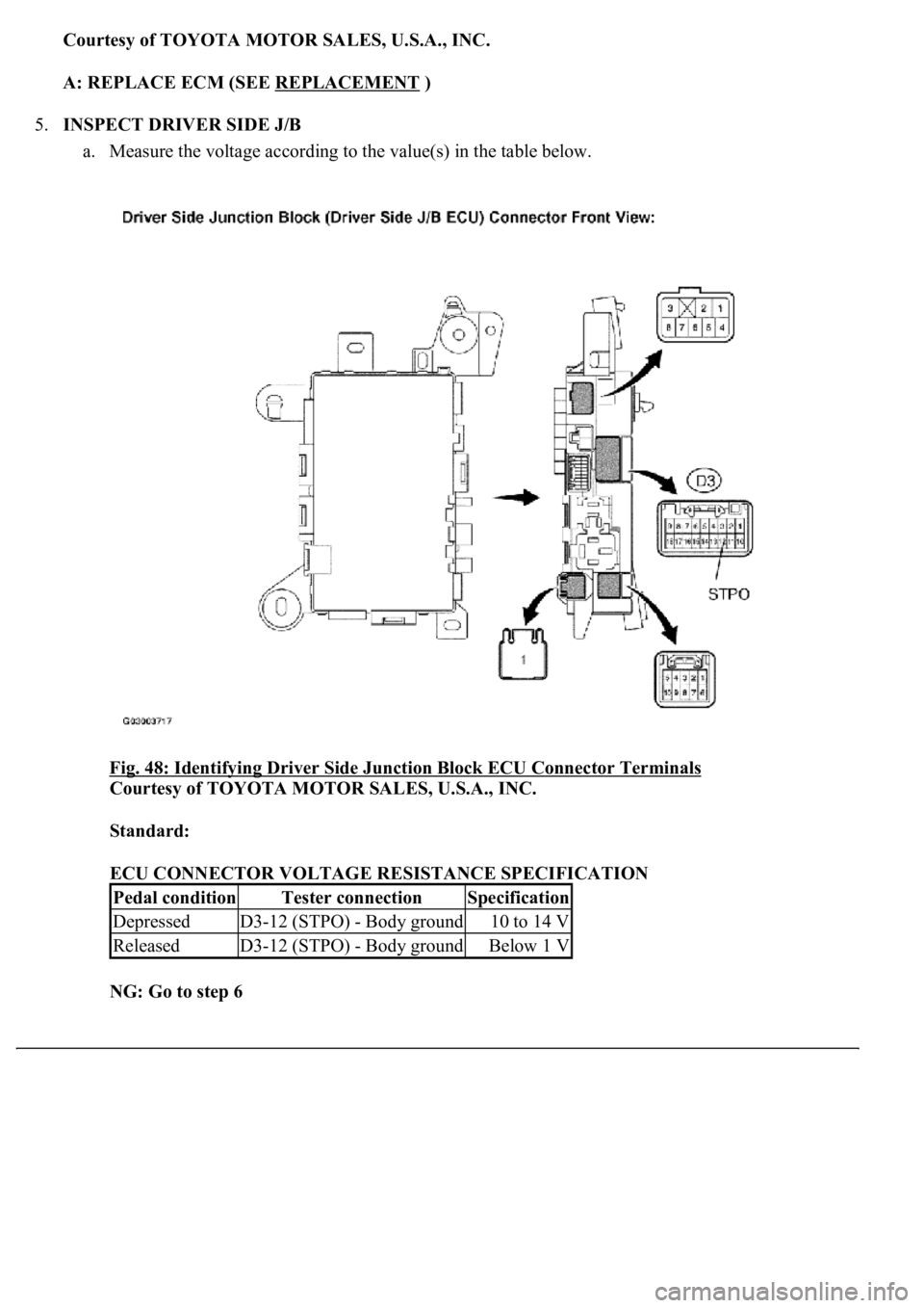
5.INSPECT DRIVER SIDE J/B
a. Measure the voltage according to the value(s) in the table below.
Fig. 48: Identifying Driver Side Junction Block ECU Connector Terminals
Courtesy of TOYOTA MOTOR SALES, U.S.A., INC.
Standard:
ECU CONNECTOR VOLTAGE RESISTANCE SPECIFICATION
NG: Go to step 6
Pedal conditionTester connectionSpecification
DepressedD3-12 (STPO) - Body ground10 to 14 V
ReleasedD3-12 (STPO) - Body groundBelow 1 V
Trending: wheel bolt torque, Control actuator, intake manifold inlet, oil reset, steering interlock cable, automatic transmission, diagram
