belt LEXUS LS430 2003 Factory Owner's Guide
[x] Cancel search | Manufacturer: LEXUS, Model Year: 2003, Model line: LS430, Model: LEXUS LS430 2003Pages: 4500, PDF Size: 87.45 MB
Page 1813 of 4500
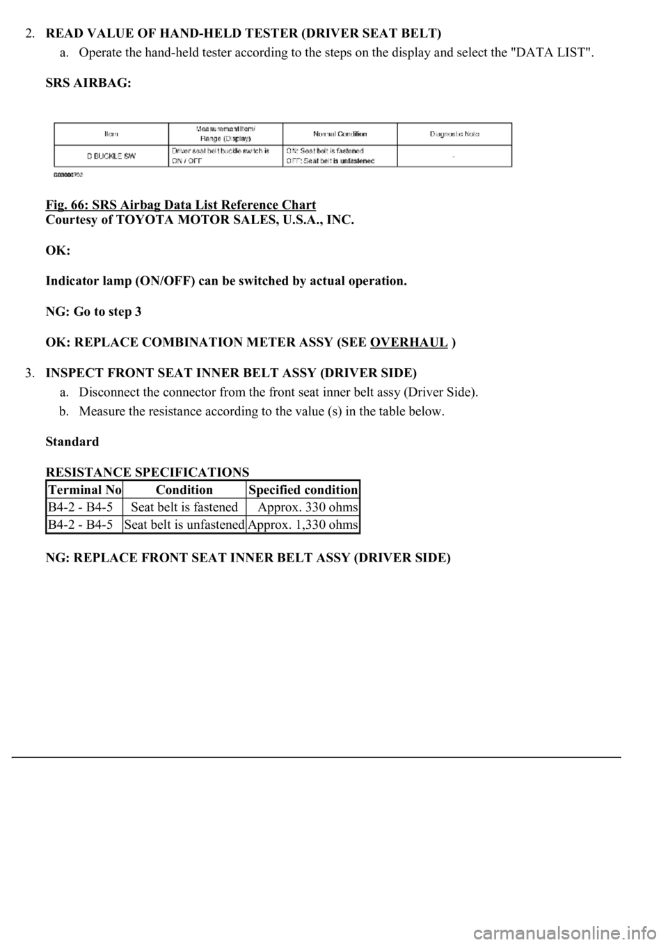
2.READ VALUE OF HAND-HELD TESTER (DRIVER SEAT BELT)
a. Operate the hand-held tester according to the steps on the display and select the "DATA LIST".
SRS AIRBAG:
Fig. 66: SRS Airbag Data List Reference Chart
Courtesy of TOYOTA MOTOR SALES, U.S.A., INC.
OK:
Indicator lamp (ON/OFF) can be switched by actual operation.
NG: Go to step 3
OK: REPLACE COMBINATION METER ASSY (SEE OVERHAUL
)
3.INSPECT FRONT SEAT INNER BELT ASSY (DRIVER SIDE)
a. Disconnect the connector from the front seat inner belt assy (Driver Side).
b. Measure the resistance according to the value (s) in the table below.
Standard
RESISTANCE SPECIFICATIONS
NG: REPLACE FRONT SEAT INNER BELT ASSY (DRIVER SIDE)
Terminal NoConditionSpecified condition
B4-2 - B4-5Seat belt is fastenedApprox. 330 ohms
B4-2 - B4-5Seat belt is unfastenedApprox. 1,330 ohms
Page 1814 of 4500
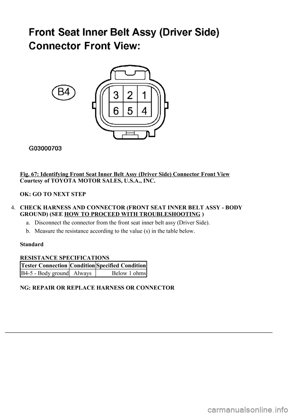
Fig. 67: Identifying Front Seat Inner Belt Assy (Driver Side) Connector Front View
Courtesy of TOYOTA MOTOR SALES, U.S.A., INC.
OK: GO TO NEXT STEP
4.CHECK HARNESS AND CONNECTOR (FRONT SEAT INNER BELT ASSY - BODY
GROUND) (SEE HOW TO PROCEED WITH TROUBLESHOOTING
)
a. Disconnect the connector from the front seat inner belt assy (Driver Side).
b. Measure the resistance according to the value (s) in the table below.
Standard
RESISTANCE SPECIFICATIONS
NG: REPAIR OR REPLACE HARNESS OR CONNECTOR
Tester ConnectionConditionSpecified Condition
B4-5 - Body groundAlwaysBelow 1 ohms
Page 1815 of 4500
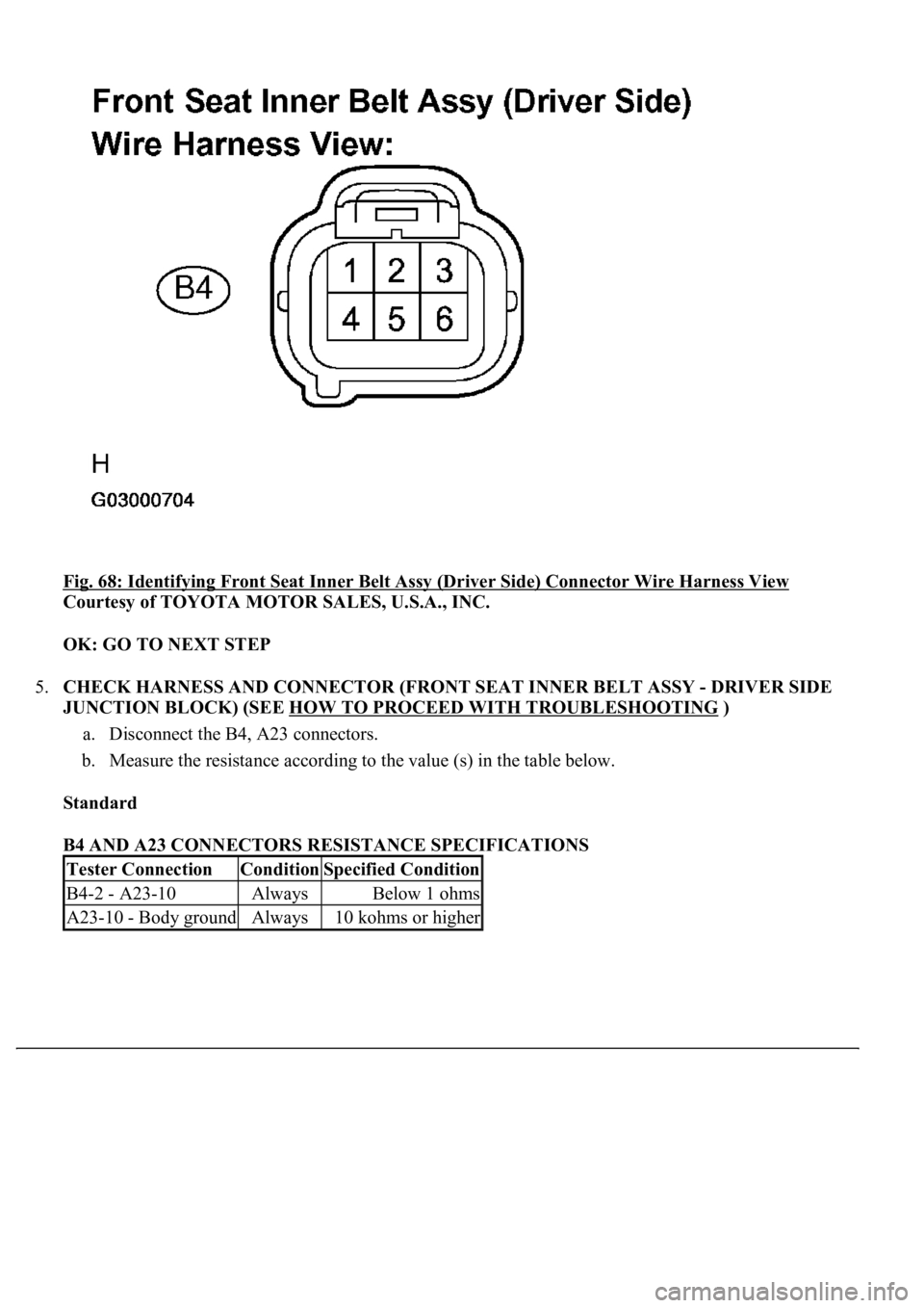
Fig. 68: Identifying Front Seat Inner Belt Assy (Driver Side) Connector Wire Harness View
Courtesy of TOYOTA MOTOR SALES, U.S.A., INC.
OK: GO TO NEXT STEP
5.CHECK HARNESS AND CONNECTOR (FRONT SEAT INNER BELT ASSY - DRIVER SIDE
JUNCTION BLOCK) (SEE HOW TO PROCEED WITH TROUBLESHOOTING
)
a. Disconnect the B4, A23 connectors.
b. Measure the resistance according to the value (s) in the table below.
Standard
B4 AND A23 CONNECTORS RESISTANCE SPECIFICATIONS
Tester ConnectionConditionSpecified Condition
B4-2 - A23-10AlwaysBelow 1 ohms
A23-10 - Body groundAlways10 kohms or higher
Page 1817 of 4500
Courtesy of TOYOTA MOTOR SALES, U.S.A., INC.
NG: REPAIR OR REPLACE HARNESS OR CONNECTOR
OK: REPLACE AIRBAG SENSOR ASSY CENTER (SEE HOW TO PROCEED WITH
TROUBLESHOOTING )
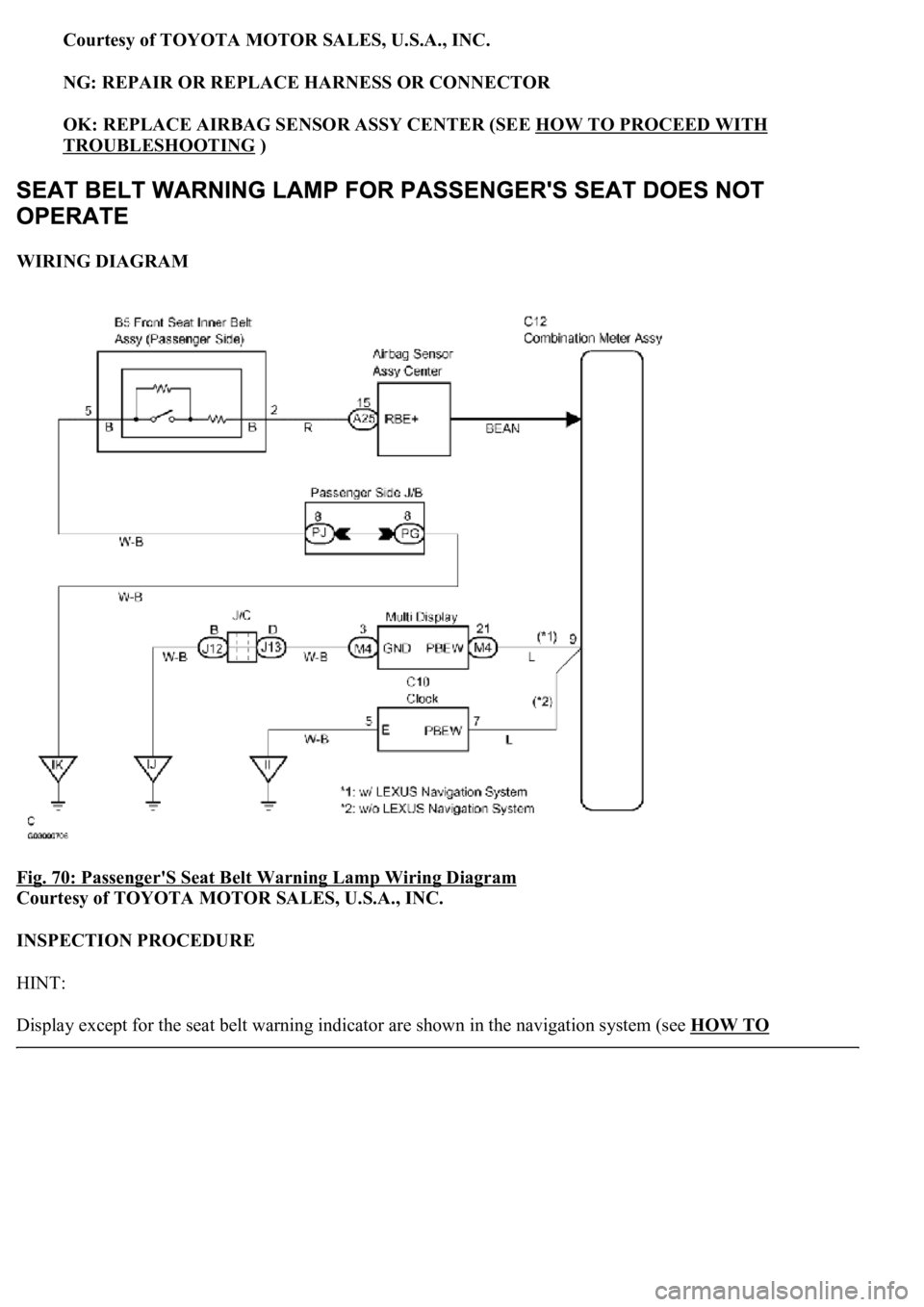
WIRING DIAGRAM
Fig. 70: Passenger'S Seat Belt Warning Lamp Wiring Diagram
Courtesy of TOYOTA MOTOR SALES, U.S.A., INC.
INSPECTION PROCEDURE
HINT:
Displa
y except for the seat belt warning indicator are shown in the navigation system (see HOW TO
Page 1818 of 4500
PROCEED WITH TROUBLESHOOTING) and A/C system (see HOW TO PROCEED WITH
TROUBLESHOOTING ).
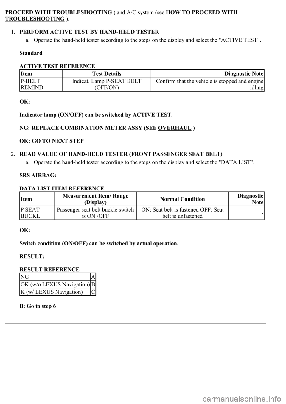
1.PERFORM ACTIVE TEST BY HAND-HELD TESTER
a. Operate the hand-held tester according to the steps on the display and select the "ACTIVE TEST".
Standard
ACTIVE TEST REFERENCE
OK:
Indicator lamp (ON/OFF) can be switched by ACTIVE TEST.
NG: REPLACE COMBINATION METER ASSY (SEE OVERHAUL
)
OK: GO TO NEXT STEP
2.READ VALUE OF HAND-HELD TESTER (FRONT PASSENGER SEAT BELT)
a. Operate the hand-held tester according to the steps on the display and select the "DATA LIST".
SRS AIRBAG:
DATA LIST ITEM REFERENCE
OK:
Switch condition (ON/OFF) can be switched by actual operation.
RESULT:
RESULT REFERENCE
B: Go to step 6
ItemTest DetailsDiagnostic Note
P-BELT
REMINDIndicat. Lamp P-SEAT BELT
(OFF/ON)Confirm that the vehicle is stopped and engine
idling
ItemMeasurement Item/ Range
(Display)Normal ConditionDiagnostic
Note
P SEAT
BUCKLPassenger seat belt buckle switch
is ON /OFFON: Seat belt is fastened OFF: Seat
belt is unfastened-
NGA
OK (w/o LEXUS Navigation)B
K (w/ LEXUS Navigation)C
Page 1819 of 4500
C: Go to step 9
A: GO TO NEXT STEP
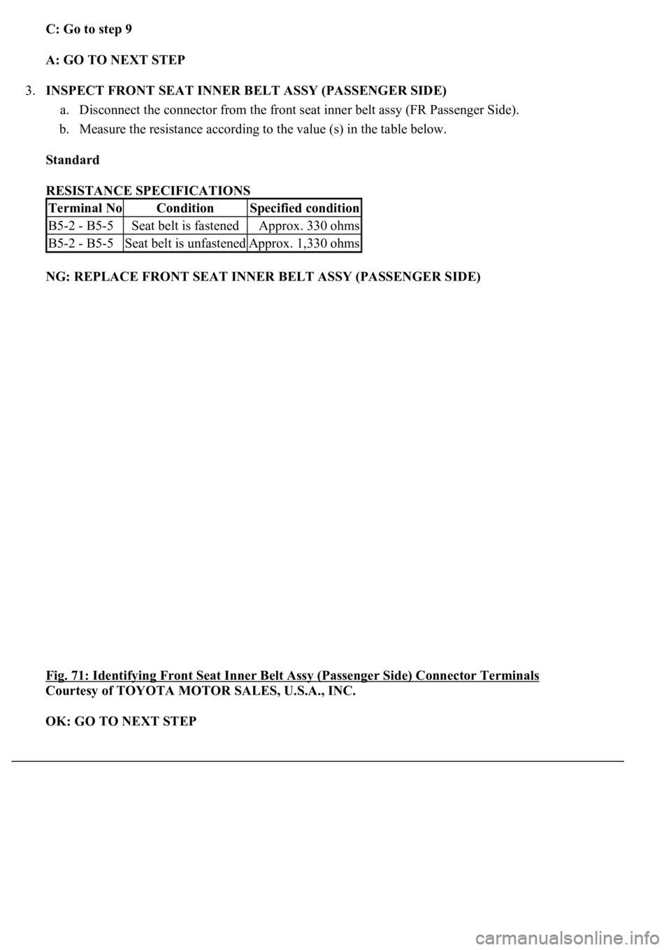
3.INSPECT FRONT SEAT INNER BELT ASSY (PASSENGER SIDE)
a. Disconnect the connector from the front seat inner belt assy (FR Passenger Side).
b. Measure the resistance according to the value (s) in the table below.
Standard
RESISTANCE SPECIFICATIONS
NG: REPLACE FRONT SEAT INNER BELT ASSY (PASSENGER SIDE)
Fig. 71: Identifying Front Seat Inner Belt Assy (Passenger Side) Connector Terminals
Courtesy of TOYOTA MOTOR SALES, U.S.A., INC.
OK: GO TO NEXT STEP
Terminal NoConditionSpecified condition
B5-2 - B5-5Seat belt is fastenedApprox. 330 ohms
B5-2 - B5-5Seat belt is unfastenedApprox. 1,330 ohms
Page 1820 of 4500
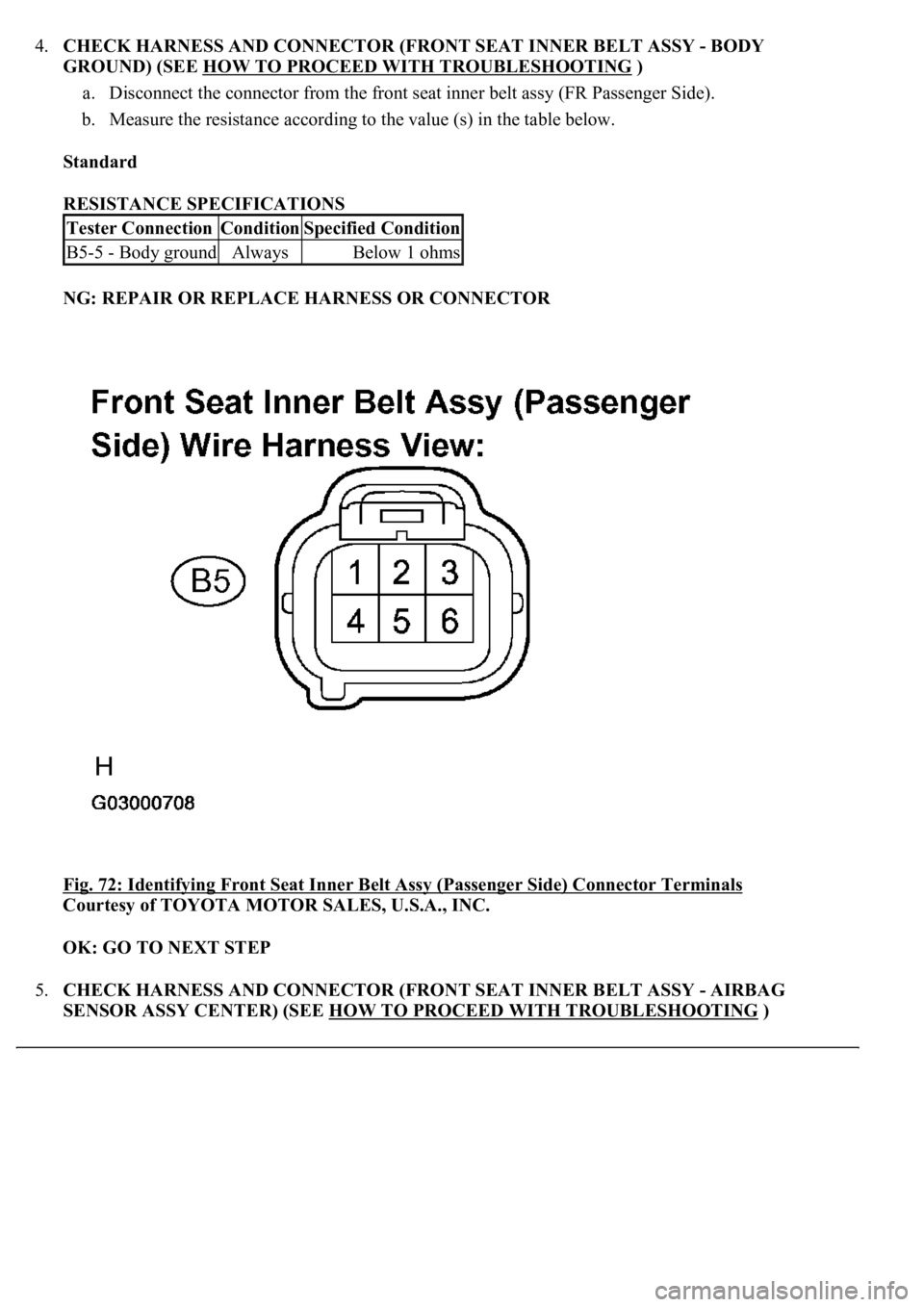
4.CHECK HARNESS AND CONNECTOR (FRONT SEAT INNER BELT ASSY - BODY
GROUND) (SEE HOW TO PROCEED WITH TROUBLESHOOTING
)
a. Disconnect the connector from the front seat inner belt assy (FR Passenger Side).
b. Measure the resistance according to the value (s) in the table below.
Standard
RESISTANCE SPECIFICATIONS
NG: REPAIR OR REPLACE HARNESS OR CONNECTOR
Fig. 72: Identifying Front Seat Inner Belt Assy (Passenger Side) Connector Terminals
Courtesy of TOYOTA MOTOR SALES, U.S.A., INC.
OK: GO TO NEXT STEP
5.CHECK HARNESS AND CONNECTOR (FRONT SEAT INNER BELT ASSY - AIRBAG
SENSOR ASSY CENTER) (SEE HOW TO PROCEED WITH TROUBLESHOOTING
)
Tester ConnectionConditionSpecified Condition
B5-5 - Body groundAlwaysBelow 1 ohms
Page 1823 of 4500
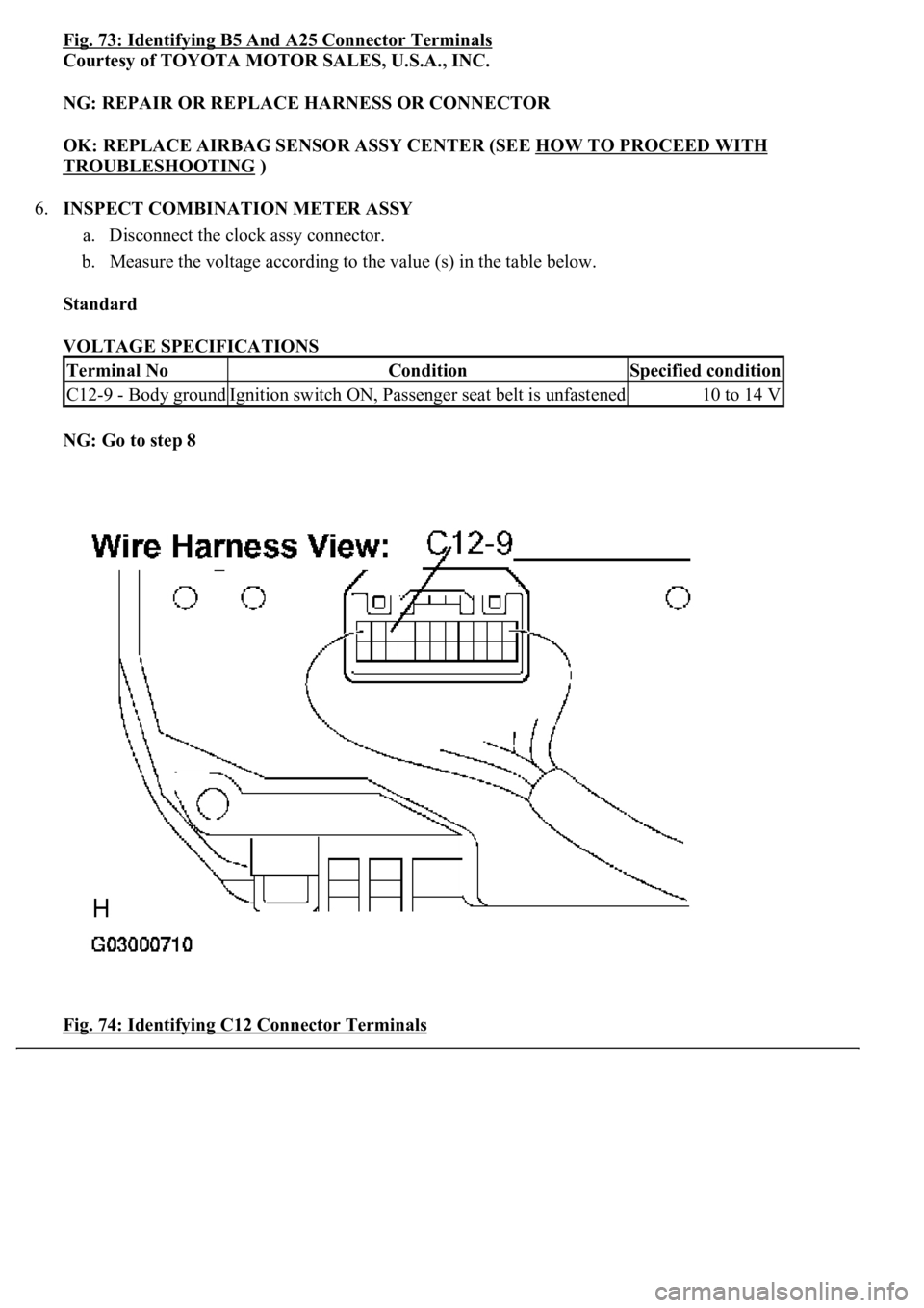
Fig. 73: Identifying B5 And A25 Connector Terminals
Courtesy of TOYOTA MOTOR SALES, U.S.A., INC.
NG: REPAIR OR REPLACE HARNESS OR CONNECTOR
OK: REPLACE AIRBAG SENSOR ASSY CENTER (SEE HOW TO PROCEED WITH
TROUBLESHOOTING )
6.INSPECT COMBINATION METER ASSY
a. Disconnect the clock assy connector.
b. Measure the voltage according to the value (s) in the table below.
Standard
VOLTAGE SPECIFICATIONS
NG: Go to step 8
Fig. 74: Identifying C12 Connector Terminals
Terminal NoConditionSpecified condition
C12-9 - Body groundIgnition switch ON, Passenger seat belt is unfastened10 to 14 V
Page 1824 of 4500
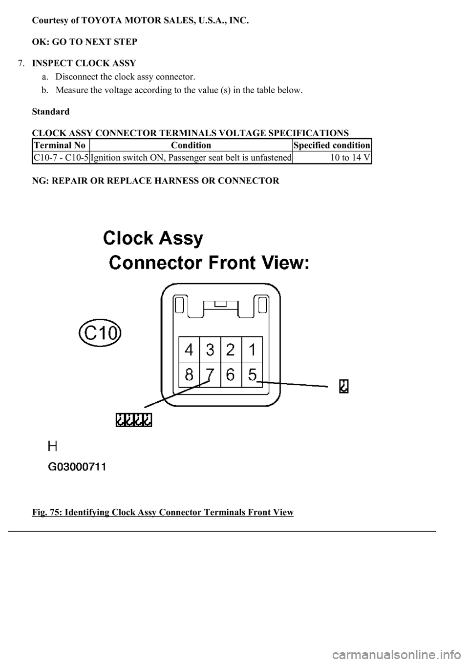
Courtesy of TOYOTA MOTOR SALES, U.S.A., INC.
OK: GO TO NEXT STEP
7.INSPECT CLOCK ASSY
a. Disconnect the clock assy connector.
b. Measure the voltage according to the value (s) in the table below.
Standard
CLOCK ASSY CONNECTOR TERMINALS VOLTAGE SPECIFICATIONS
NG: REPAIR OR REPLACE HARNESS OR CONNECTOR
Fig. 75: Identifying Clock Assy Connector Terminals Front View
Terminal NoConditionSpecified condition
C10-7 - C10-5Ignition switch ON, Passenger seat belt is unfastened10 to 14 V
Page 1827 of 4500
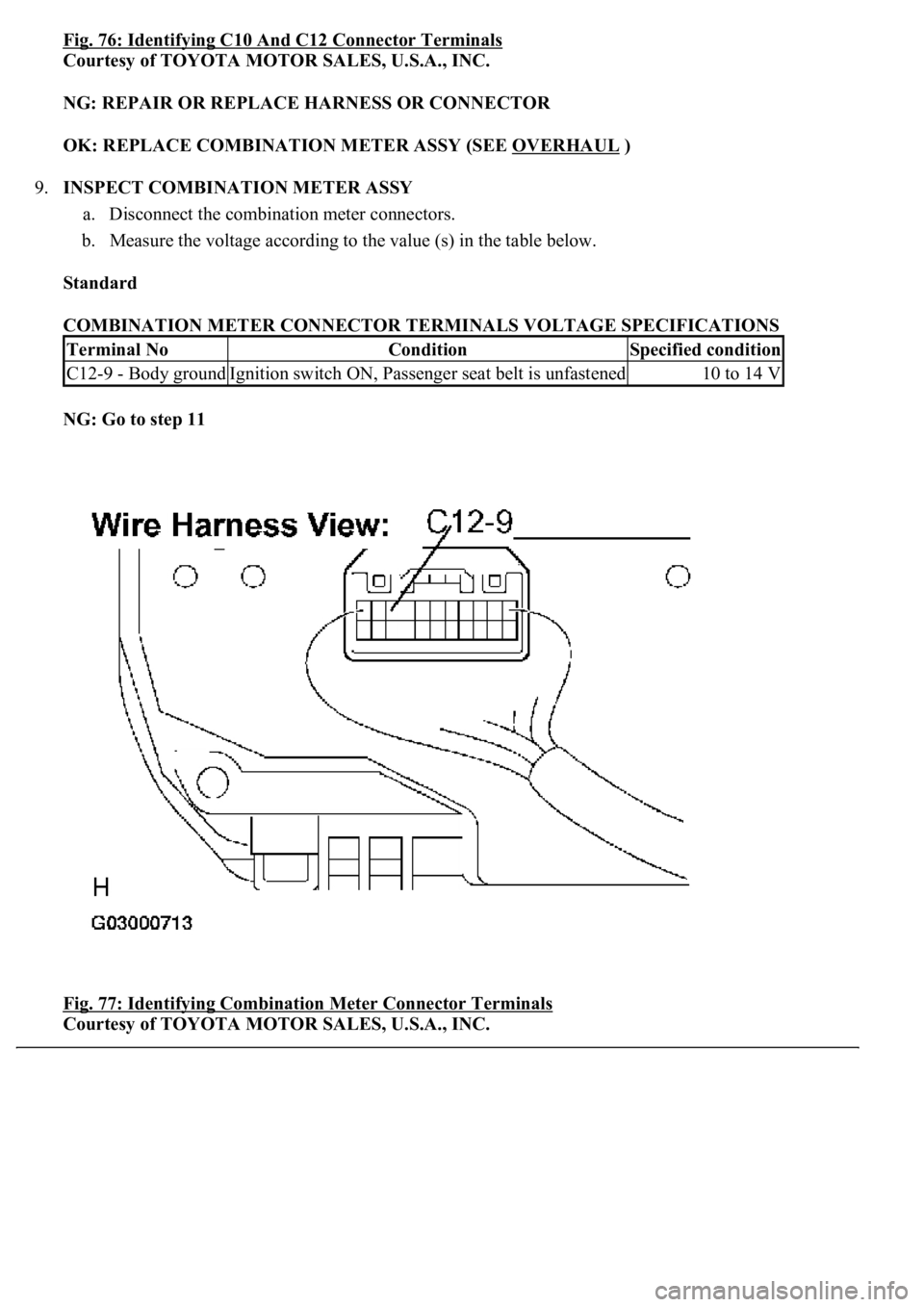
Fig. 76: Identifying C10 And C12 Connector Terminals
Courtesy of TOYOTA MOTOR SALES, U.S.A., INC.
NG: REPAIR OR REPLACE HARNESS OR CONNECTOR
OK: REPLACE COMBINATION METER ASSY (SEE OVERHAUL
)
9.INSPECT COMBINATION METER ASSY
a. Disconnect the combination meter connectors.
b. Measure the voltage according to the value (s) in the table below.
Standard
COMBINATION METER CONNECTOR TERMINALS VOLTAGE SPECIFICATIONS
NG: Go to step 11
Fig. 77: Identifying Combination Meter Connector Terminals
Courtesy of TOYOTA MOTOR SALES, U.S.A., INC.
Terminal NoConditionSpecified condition
C12-9 - Body groundIgnition switch ON, Passenger seat belt is unfastened10 to 14 V