belt LEXUS LS430 2003 Factory Workshop Manual
[x] Cancel search | Manufacturer: LEXUS, Model Year: 2003, Model line: LS430, Model: LEXUS LS430 2003Pages: 4500, PDF Size: 87.45 MB
Page 3033 of 4500
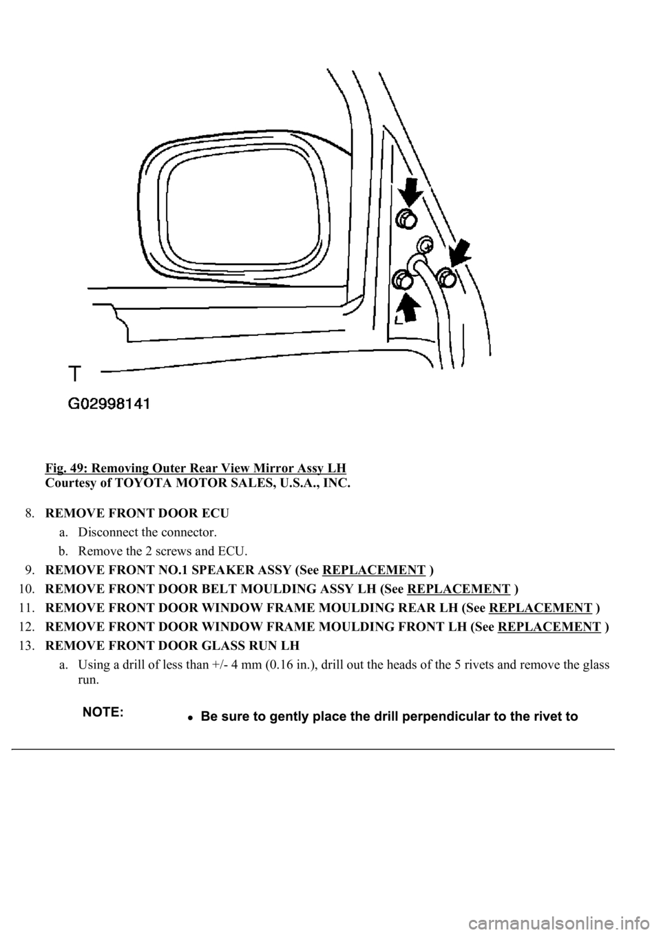
Fig. 49: Removing Outer Rear View Mirror Assy LH
Courtesy of TOYOTA MOTOR SALES, U.S.A., INC.
8.REMOVE FRONT DOOR ECU
a. Disconnect the connector.
b. Remove the 2 screws and ECU.
9.REMOVE FRONT NO.1 SPEAKER ASSY (See REPLACEMENT
)
10.REMOVE FRONT DOOR BELT MOULDING ASSY LH (See REPLACEMENT
)
11.REMOVE FRONT DOOR WINDOW FRAME MOULDING REAR LH (See REPLACEMENT
)
12.REMOVE FRONT DOOR WINDOW FRAME MOULDING FRONT LH (See REPLACEMENT
)
13.REMOVE FRONT DOOR GLASS RUN LH
a. Using a drill of less than +/- 4 mm (0.16 in.), drill out the heads of the 5 rivets and remove the glass
run.
Page 3073 of 4500

Fig. 86: Inspecting Rear Door Panel Sub-Assy LH
Courtesy of TOYOTA MOTOR SALES, U.S.A., INC.
AREA MEASUREMENT REFERENCE STANDARD:
2.ADJUST REAR DOOR PANEL SUB-ASSY LH
a. Disconnect the negative (-) terminal cable from the battery.
b. Remove the front door inside scuff plate (see REPLACEMENT
).
c. Remove the rear door inside scuff plate (see REPLACEMENT
).
d. Remove the center pillar lower garnish (see REPLACEMENT
).
e. Remove the retractor part of the front seat belt (see REPLACEMENT
).
AreaMeasurementAreaMeasurement
A8.0 +/- 1.5 mm (0.315 +/- 0.059 in.)C4.0 +/- 1.5 mm (0.157 +/- 0.059 in.)
B2.5 +/- 1.5 mm (0.098 +/- 0.059 in.)D4.0 +/- 1.5 mm (0.157 +/- 0.059 in.)
Page 3090 of 4500

Fig. 103: Removing Remaining Tape On Door Side
Courtesy of TOYOTA MOTOR SALES, U.S.A., INC.
8.REMOVE REAR DOOR ECU
a. Remove the 2 screws and ECU.
9.REMOVE REAR SPEAKER ASSY NO.2 (See REPLACEMENT
)
10.REMOVE REAR SPEAKER ASSY (See REPLACEMENT
)
11.REMOVE REAR DOOR BELT MOULDING ASSY LH (See REPLACEMENT
)
12.REMOVE REAR DOOR WINDOW FRAME MOULDING FRONT LH (See REPLACEMENT
)
13.REMOVE REAR DOOR WINDOW FRAME MOULDING UPPER LH (See REPLACEMENT
)
14.REMOVE REAR DOOR WINDOW DIVISION BAR SUB-ASSY LH
a. Remove the 2 nuts, bolt and division bar.
Page 3279 of 4500
INSPECTION
1.INSPECT ENGINE COOLANT (See REPLACEMENT
)
2.INSPECT ENGINE OIL (See ON
-VEHICLE INSPECTION )
3.INSPECT BATTERY (See REPLACEMENT
)
4.INSPECT AIR CLEANER FILTER ELEMENT SUB-ASSY
5.INSPECT SPARK PLUG (See REPLACEMENT
)
6.INSPECT FAN AND GENERATOR V BELT
HINT:
Use of the automatic tensioner has made tension and flexibility measurements unnecessary.
a. Check that the indicator mark on the automatic tensioner is within range A as shown in the
illustration.
b. When the mark is out of the standard range, replace the V belt with a new one.
Page 3280 of 4500
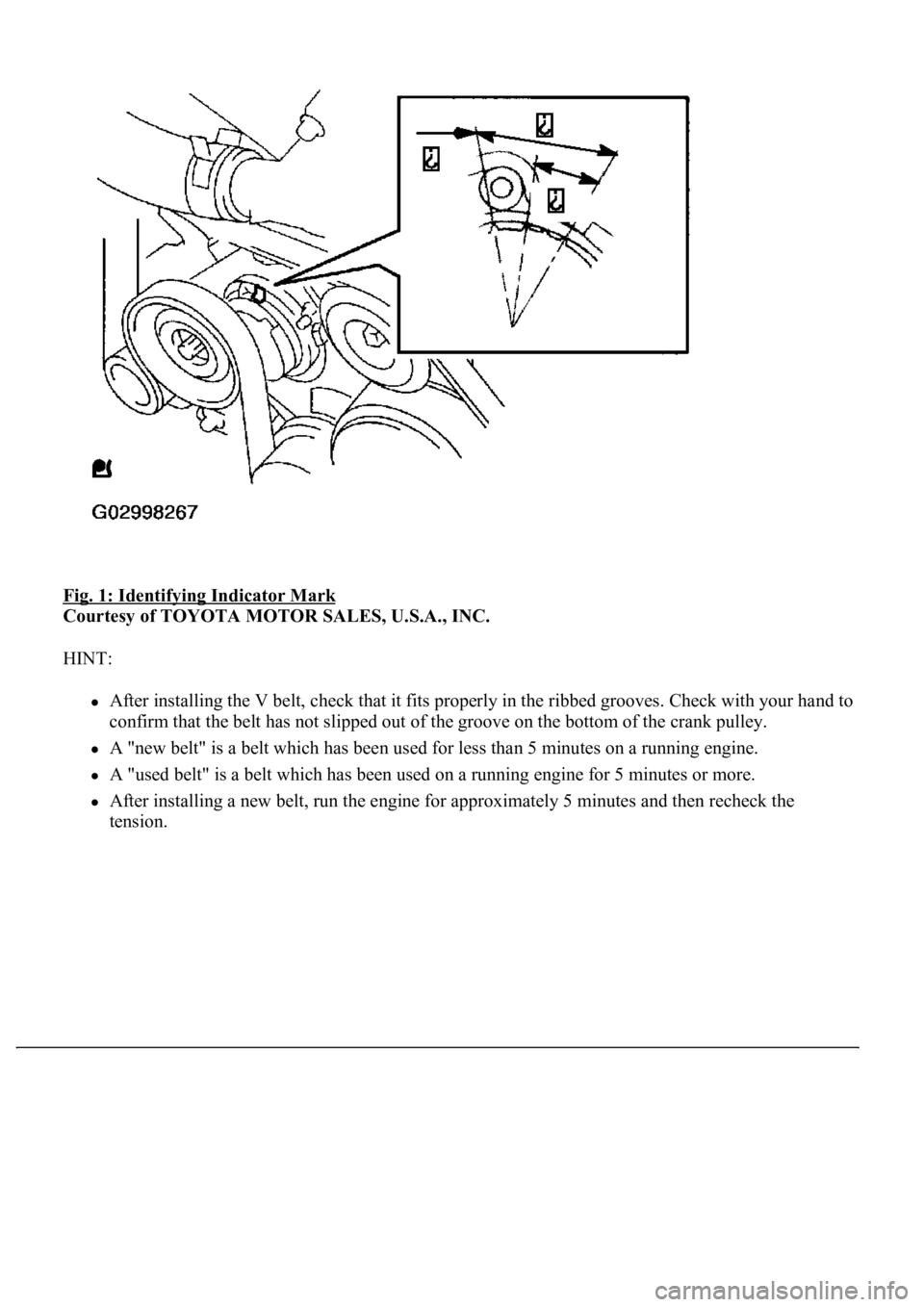
Fig. 1: Identifying Indicator Mark
Courtesy of TOYOTA MOTOR SALES, U.S.A., INC.
HINT:
After installing the V belt, check that it fits properly in the ribbed grooves. Check with your hand to
confirm that the belt has not slipped out of the groove on the bottom of the crank pulley.
A "new belt" is a belt which has been used for less than 5 minutes on a running engine.
A "used belt" is a belt which has been used on a running engine for 5 minutes or more.
After installing a new belt, run the engine for approximately 5 minutes and then recheck the
tension.
Page 3287 of 4500

Fig. 7: CO/HC Symptom Reference Chart
Courtesy of TOYOTA MOTOR SALES, U.S.A., INC.
REPLACEMENT
1.REMOVE AIR CLEANER INLET NO.1
2.REMOVE FAN AND GENERATOR V BELT
a. Loosen the belt tension by turning the belt tensioner counterclockwise, and remove the V belt.
HINT:
The tension pulle
y has a left-hand thread.
Page 3288 of 4500
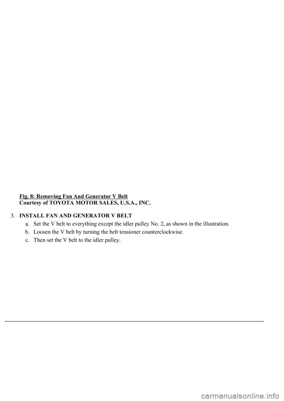
Fig. 8: Removing Fan And Generator V Belt
Courtesy of TOYOTA MOTOR SALES, U.S.A., INC.
3.INSTALL FAN AND GENERATOR V BELT
a. Set the V belt to everything except the idler pulley No. 2, as shown in the illustration.
b. Loosen the V belt by turning the belt tensioner counterclockwise.
c. Then set the V belt to the idler pulle
y.
Page 3289 of 4500

Fig. 9: Installing Fan And Generator V Belt
Courtesy of TOYOTA MOTOR SALES, U.S.A., INC.
d. After a new belt has been installed, check that the mark is within range B as shown in the
illustration.
Page 3290 of 4500
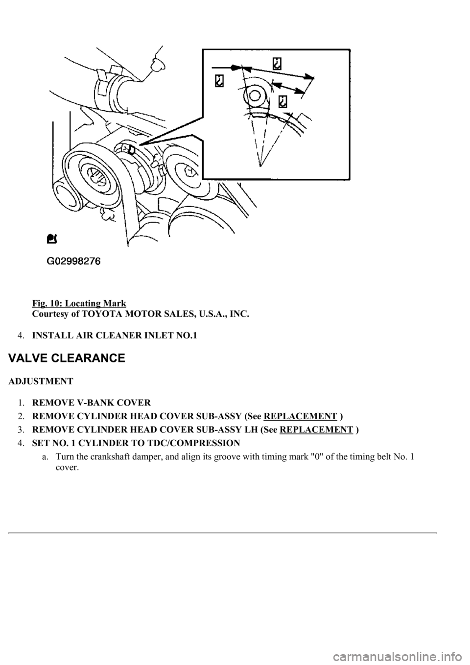
Fig. 10: Locating Mark
Courtesy of TOYOTA MOTOR SALES, U.S.A., INC.
4.INSTALL AIR CLEANER INLET NO.1
ADJUSTMENT
1.REMOVE V-BANK COVER
2.REMOVE CYLINDER HEAD COVER SUB-ASSY (See REPLACEMENT
)
3.REMOVE CYLINDER HEAD COVER SUB-ASSY LH (See REPLACEMENT
)
4.SET NO. 1 CYLINDER TO TDC/COMPRESSION
a. Turn the crankshaft damper, and align its groove with timing mark "0" of the timing belt No. 1
cover.
Page 3313 of 4500
13.DRAIN AUTOMATIC TRANSMISSION FLUID
14.REMOVE RADIATOR ASSY (See REPLACEMENT
)
15.DISCONNECT FUEL PIPE SUB-ASSY NO.2 (See REPLACEMENT
)
16.REMOVE FAN AND GENERATOR V BELT (See REPLACEMENT
)
17.DISCONNECT ENGINE WIRE
a. Disconnect the engine wire from the ECM box.
b. Remove the nut, and disconnect the generator wire from the generator.
c. Disconnect the wire for generator wire from the wire clamp on generator.
d. Remove the bolt, and disconnect the ground cable from the stay on the generator.
e. Remove the 2 bolts, and disconnect the PS oil hose from the No. 1 oil pan.
f. Remove the bolt, and disconnect the ground strap from the body.
18.DISCONNECT AIR HOSE NO.5
19.DISCONNECT FUEL VAPOR FEED HOSE NO.2
20.DISCONNECT HEATER WATER INLET HOSE A
21.DISCONNECT HEATER WATER OUTLET HOSE A (FROM HEATER UNIT)
22.DISCONNECT VANE PUMP OIL RESERVOIR ASSY
23.DISCONNECT VANE PUMP ASSY
a. Disconnect the 2 PS air hoses.
b. Remove the 2 screws and RH engine under cover.
c. Disconnect the PS oil pressure switch connector.
d. Remove the 2 bolts and nut, and disconnect the pump from the engine.
e. Support the pump securely.
24.DISCONNECT COOLER COMPRESSOR ASSY
a. Disconnect the compressor connector.
b. Disconnect the wire clamp from the wire bracket on the compressor.
c. Remove the bolt, nut and stay.
d. Remove the bolt, and disconnect the wire bracket from the compressor.
e. Remove the bolt, and disconnect the compressor from the engine.
f. Support the cooler compressor securely.
25.REMOVE FRONT FLOOR BRACE CENTER
a. Remove the 4 bolts and brace center.
26.REMOVE EXHAUST PIPE ASSY (See REPLACEMENT
)
27.REMOVE W/ CATALYST CONVERTER ASSY
28.REMOVE FRONT FLOOR HEAT INSULATOR NO.1
29.REMOVE PARKING BRAKE CABLE HEAT INSULATOR
30.REMOVE PROPELLER W/ CENTER BEARING SHAFT ASSY (See OVERHAUL
)
31.REMOVE FLOOR SHIFT GEAR SHIFTING ROD SUB-ASSY
32.REMOVE STEERING SLIDING W/ SHAFT YOKE SUB-ASSY