belt LEXUS LS430 2003 Factory Owner's Manual
[x] Cancel search | Manufacturer: LEXUS, Model Year: 2003, Model line: LS430, Model: LEXUS LS430 2003Pages: 4500, PDF Size: 87.45 MB
Page 1332 of 4500
OK: REPAIR OR REPLACE SEAT BELT CONTROL ECU SUB BUS LINE OR CONNECTOR
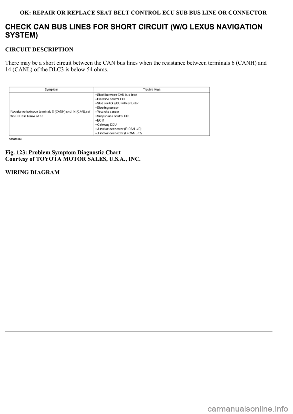
CIRCUIT DESCRIPTION
There may be a short circuit between the CAN bus lines when the resistance between terminals 6 (CANH) and
14 (CANL) of the DLC3 is below 54 ohms.
Fig. 123: Problem Symptom Diagnostic Chart
Courtesy of TOYOTA MOTOR SALES, U.S.A., INC.
WIRING DIAGRAM
Page 1396 of 4500
NG: GO TO NEXT STEP
38.CONNECT CONNECTOR
a. Reconnect the television camera ECU sub bus line connector (J52) to the LUG-CAN J/C A side
(w/earth terminal).
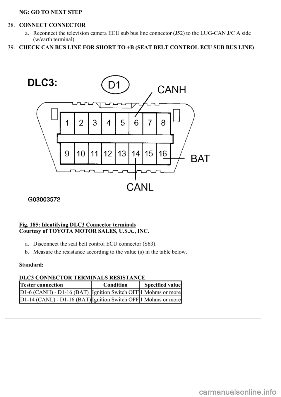
39.CHECK CAN BUS LINE FOR SHORT TO +B (SEAT BELT CONTROL ECU SUB BUS LINE)
Fig. 185: Identifying DLC3 Connector terminals
Courtesy of TOYOTA MOTOR SALES, U.S.A., INC.
a. Disconnect the seat belt control ECU connector (S63).
b. Measure the resistance according to the value (s) in the table below.
Standard:
DLC3 CONNECTOR TERMINALS RESISTANCE
Tester connectionConditionSpecified value
D1-6 (CANH) - D1-16 (BAT)Ignition Switch OFF1 Mohms or more
D1-14 (CANL) - D1-16 (BAT)Ignition Switch OFF1 Mohms or more
Page 1397 of 4500
NG: REPAIR OR REPLACE SEAT BELT CONTROL ECU SUB BUS LINE OR CONNECTOR
OK: REPLACE SEAT BELT CONTROL ECU
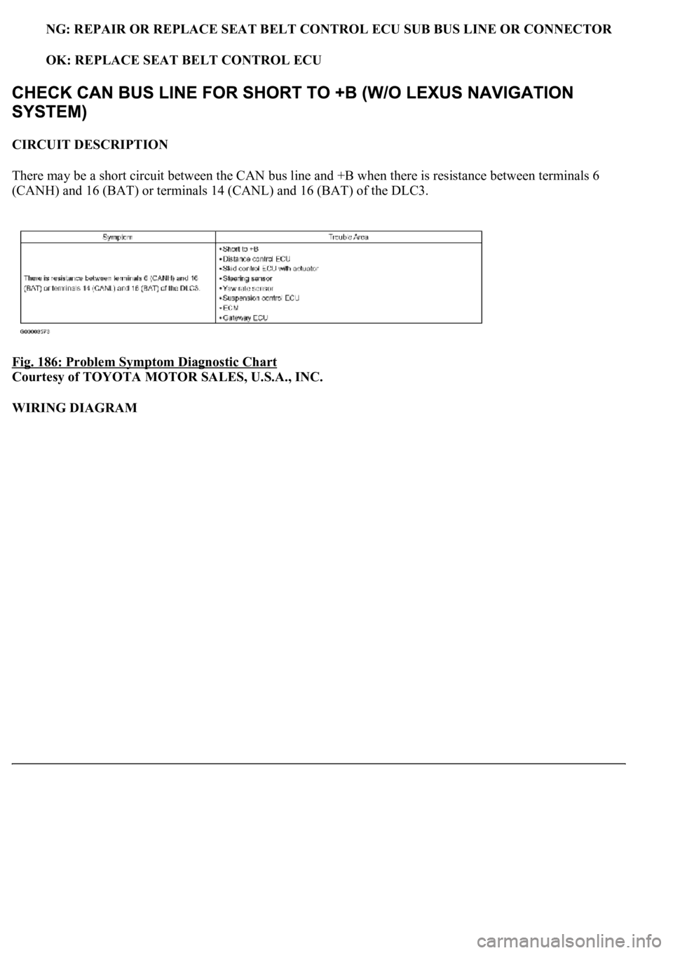
CIRCUIT DESCRIPTION
There may be a short circuit between the CAN bus line and +B when there is resistance between terminals 6
(CANH) and 16 (BAT) or terminals 14 (CANL) and 16 (BAT) of the DLC3.
Fig. 186: Problem Symptom Diagnostic Chart
Courtesy of TOYOTA MOTOR SALES, U.S.A., INC.
WIRING DIAGRAM
Page 1466 of 4500
44.CONNECT CONNECTOR
a. Reconnect the television camera ECU sub bus line connector (J52) to the LUG-CAN J/C A side
(w/earth terminal).
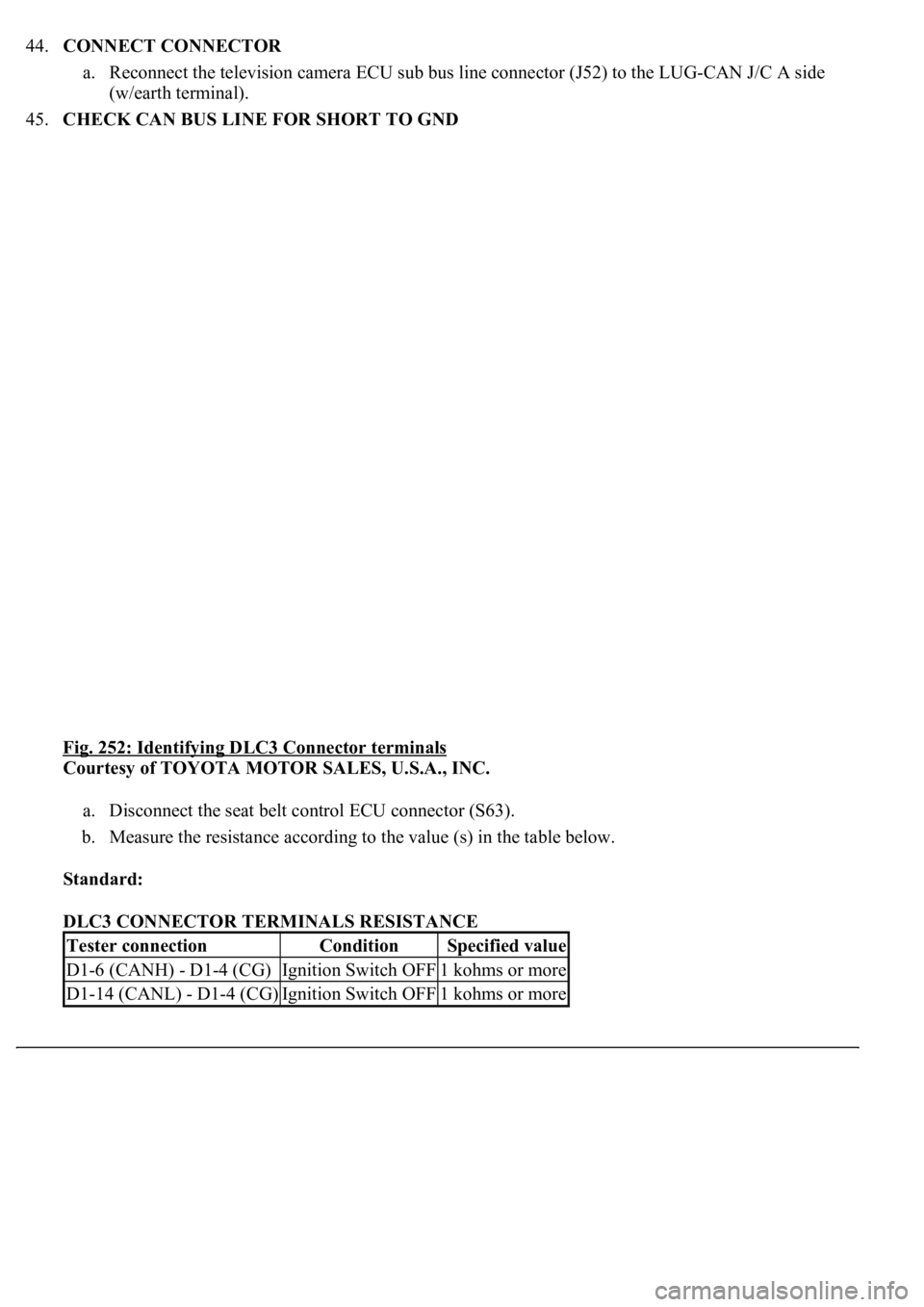
45.CHECK CAN BUS LINE FOR SHORT TO GND
Fig. 252: Identifying DLC3 Connector terminals
Courtesy of TOYOTA MOTOR SALES, U.S.A., INC.
a. Disconnect the seat belt control ECU connector (S63).
b. Measure the resistance according to the value (s) in the table below.
Standard:
DLC3 CONNECTOR TERMINALS RESISTANCE
Tester connectionConditionSpecified value
D1-6 (CANH) - D1-4 (CG)Ignition Switch OFF1 kohms or more
D1-14 (CANL) - D1-4 (CG)Ignition Switch OFF1 kohms or more
Page 1467 of 4500
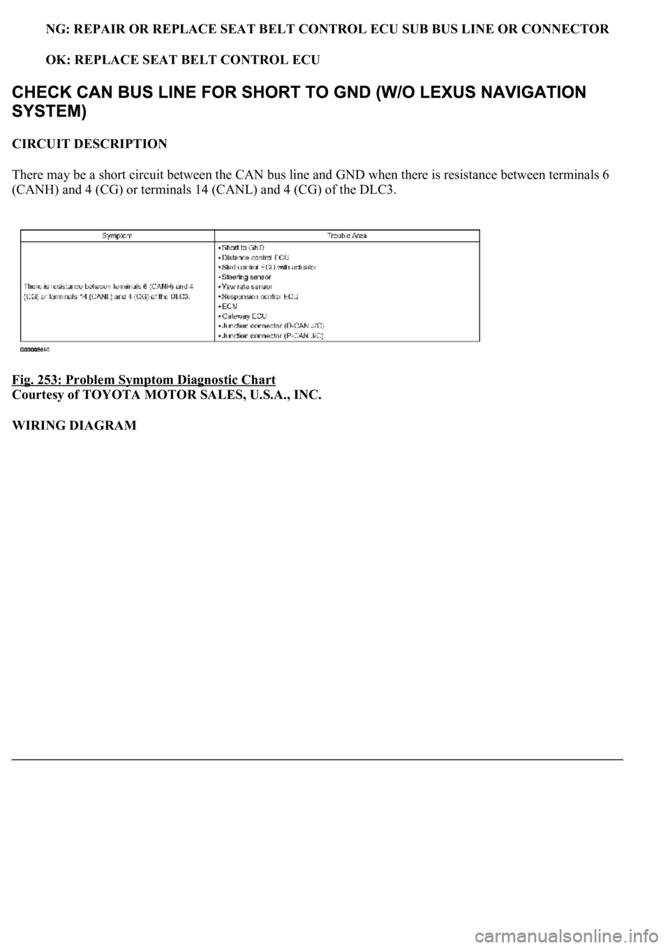
NG: REPAIR OR REPLACE SEAT BELT CONTROL ECU SUB BUS LINE OR CONNECTOR
OK: REPLACE SEAT BELT CONTROL ECU
CIRCUIT DESCRIPTION
There may be a short circuit between the CAN bus line and GND when there is resistance between terminals 6
(CANH) and 4 (CG) or terminals 14 (CANL) and 4 (CG) of the DLC3.
Fig. 253: Problem Symptom Diagnostic Chart
Courtesy of TOYOTA MOTOR SALES, U.S.A., INC.
WIRING DIAGRAM
Page 1744 of 4500
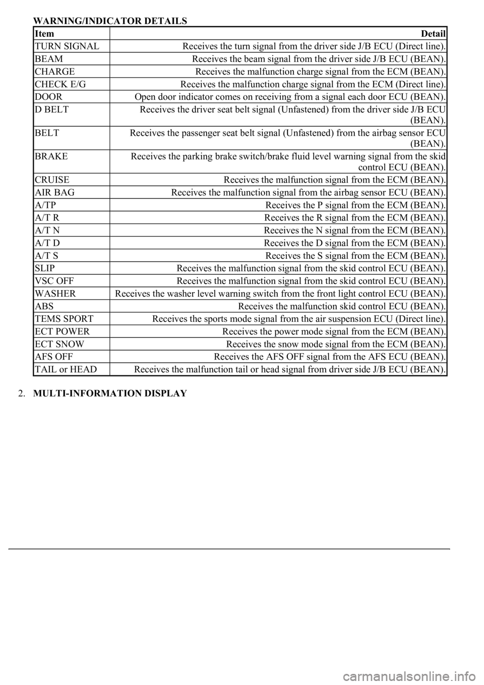
WARNING/INDICATOR DETAILS
2.MULTI-INFORMATION DISPLAY
ItemDetail
TURN SIGNALReceives the turn signal from the driver side J/B ECU (Direct line).
BEAMReceives the beam signal from the driver side J/B ECU (BEAN).
CHARGEReceives the malfunction charge signal from the ECM (BEAN).
CHECK E/GReceives the malfunction charge signal from the ECM (Direct line).
DOOROpen door indicator comes on receiving from a signal each door ECU (BEAN).
D BELTReceives the driver seat belt signal (Unfastened) from the driver side J/B ECU
(BEAN).
BELTReceives the passenger seat belt signal (Unfastened) from the airbag sensor ECU
(BEAN).
BRAKEReceives the parking brake switch/brake fluid level warning signal from the skid
control ECU (BEAN).
CRUISEReceives the malfunction signal from the ECM (BEAN).
AIR BAGReceives the malfunction signal from the airbag sensor ECU (BEAN).
A/TPReceives the P signal from the ECM (BEAN).
A/T RReceives the R signal from the ECM (BEAN).
A/T NReceives the N signal from the ECM (BEAN).
A/T DReceives the D signal from the ECM (BEAN).
A/T SReceives the S signal from the ECM (BEAN).
SLIPReceives the malfunction signal from the skid control ECU (BEAN).
VSC OFFReceives the malfunction signal from the skid control ECU (BEAN).
WASHERReceives the washer level warning switch from the front light control ECU (BEAN).
ABSReceives the malfunction skid control ECU (BEAN).
TEMS SPORTReceives the sports mode signal from the air suspension ECU (Direct line).
ECT POWERReceives the power mode signal from the ECM (BEAN).
ECT SNOWReceives the snow mode signal from the ECM (BEAN).
AFS OFFReceives the AFS OFF signal from the AFS ECU (BEAN).
TAIL or HEADReceives the malfunction tail or head signal from driver side J/B ECU (BEAN).
Page 1763 of 4500
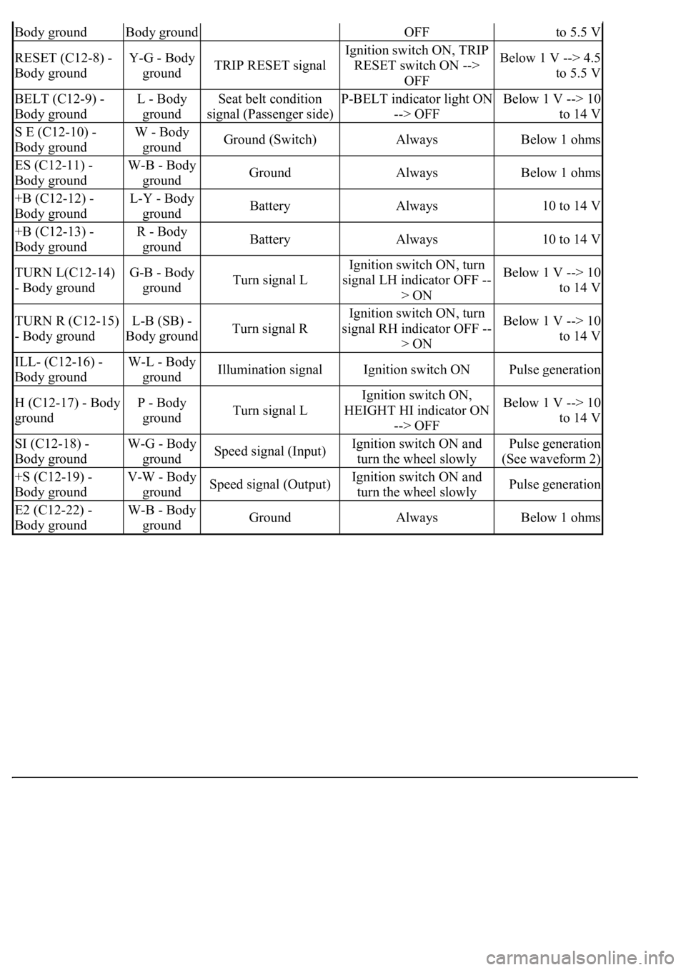
Body groundBody groundOFFto 5.5 V
RESET (C12-8) -
Body groundY-G - Body
groundTRIP RESET signal
Ignition switch ON, TRIP
RESET switch ON -->
OFFBelow 1 V --> 4.5
to 5.5 V
BELT (C12-9) -
Body groundL - Body
groundSeat belt condition
signal (Passenger side)P-BELT indicator light ON
--> OFFBelow 1 V --> 10
to 14 V
S E (C12-10) -
Body groundW - Body
groundGround (Switch)AlwaysBelow 1 ohms
ES (C12-11) -
Body groundW-B - Body
groundGroundAlwaysBelow 1 ohms
+B (C12-12) -
Body groundL-Y - Body
groundBatteryAlways10 to 14 V
+B (C12-13) -
Body groundR - Body
groundBatteryAlways10 to 14 V
TURN L(C12-14)
- Body groundG-B - Body
groundTurn signal L
Ignition switch ON, turn
signal LH indicator OFF --
> ONBelow 1 V --> 10
to 14 V
TURN R (C12-15)
- Body groundL-B (SB) -
Body groundTurn signal R
Ignition switch ON, turn
signal RH indicator OFF --
> ONBelow 1 V --> 10
to 14 V
ILL- (C12-16) -
Body groundW-L - Body
groundIllumination signalIgnition switch ONPulse generation
H (C12-17) - Body
groundP - Body
groundTurn signal L
Ignition switch ON,
HEIGHT HI indicator ON
--> OFFBelow 1 V --> 10
to 14 V
SI (C12-18) -
Body groundW-G - Body
groundSpeed signal (Input)Ignition switch ON and
turn the wheel slowlyPulse generation
(See waveform 2)
+S (C12-19) -
Body groundV-W - Body
groundSpeed signal (Output)Ignition switch ON and
turn the wheel slowlyPulse generation
E2 (C12-22) -
Body groundW-B - Body
groundGroundAlwaysBelow 1 ohms
Page 1780 of 4500
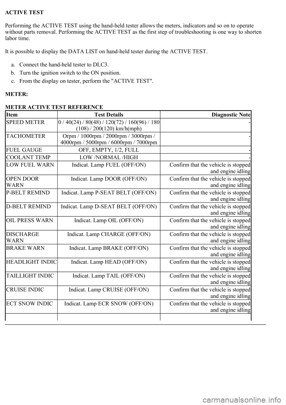
ACTIVE TEST
Performing the ACTIVE TEST using the hand-held tester allows the meters, indicators and so on to operate
without parts removal. Performing the ACTIVE TEST as the first step of troubleshooting is one way to shorten
labor time.
It is possible to display the DATA LIST on hand-held tester during the ACTIVE TEST.
a. Connect the hand-held tester to DLC3.
b. Turn the ignition switch to the ON position.
c. From the display on tester, perform the "ACTIVE TEST".
METER:
METER ACTIVE TEST REFERENCE
ItemTest DetailsDiagnostic Note
SPEED METER0 / 40(24) / 80(48) / 120(72) / 160(96) / 180
(108) / 200(120) km/h(mph)-
TACHOMETEROrpm / 1000rpm / 2000rpm / 3000rpm /
4000rpm / 5000rpm / 6000rpm / 7000rpm-
FUEL GAUGEOFF, EMPTY, 1/2, FULL-
COOLANT TEMPLOW /NORMAL /HIGH-
LOW FUEL WARNIndicat. Lamp FUEL (OFF/ON)Confirm that the vehicle is stopped
and engine idling
OPEN DOOR
WARNIndicat. Lamp DOOR (OFF/ON)Confirm that the vehicle is stopped
and engine idling
P-BELT REMINDIndicat. Lamp P-SEAT BELT (OFF/ON)Confirm that the vehicle is stopped
and engine idling
D-BELT REMINDIndicat. Lamp D-SEAT BELT (OFF/ON)Confirm that the vehicle is stopped
and engine idling
OIL PRESS WARNIndicat. Lamp OIL (OFF/ON)Confirm that the vehicle is stopped
and engine idling
DISCHARGE
WARNIndicat. Lamp CHARGE (OFF/ON)Confirm that the vehicle is stopped
and engine idling
BRAKE WARNIndicat. Lamp BRAKE (OFF/ON)Confirm that the vehicle is stopped
and engine idling
HEADLIGHT INDICIndicat. Lamp HEAD (OFF/ON)Confirm that the vehicle is stopped
and engine idling
TAILLIGHT INDICIndicat. Lamp TAIL (OFF/ON)Confirm that the vehicle is stopped
and engine idling
CRUISE INDICIndicat. Lamp CRUISE (OFF/ON)Confirm that the vehicle is stopped
and engine idling
ECT SNOW INDICIndicat. Lamp ECR SNOW (OFF/ON)Confirm that the vehicle is stopped
and engine idling
Page 1782 of 4500
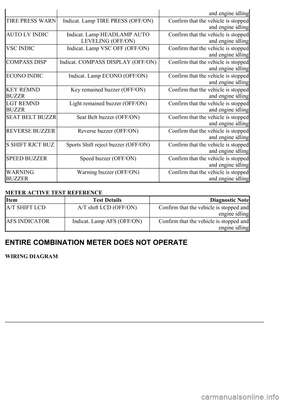
METER ACTIVE TEST REFERENCE
WIRING DIAGRAM
and engine idling
TIRE PRESS WARNIndicat. Lamp TIRE PRESS (OFF/ON)Confirm that the vehicle is stopped
and engine idling
AUTO LV INDICIndicat. Lamp HEADLAMP AUTO
LEVELING (OFF/ON)Confirm that the vehicle is stopped
and engine idling
VSC INDICIndicat. Lamp VSC OFF (OFF/ON)Confirm that the vehicle is stopped
and engine idling
COMPASS DISPIndicat. COMPASS DISPLAY (OFF/ON)Confirm that the vehicle is stopped
and engine idling
ECONO INDICIndicat. Lamp ECONO (OFF/ON)Confirm that the vehicle is stopped
and engine idling
KEY REMND
BUZZRKey remained buzzer (OFF/ON)Confirm that the vehicle is stopped
and engine idling
LGT REMND
BUZZRLight remained buzzer (OFF/ON)Confirm that the vehicle is stopped
and engine idling
SEAT BELT BUZZRSeat Belt buzzer (OFF/ON)Confirm that the vehicle is stopped
and engine idling
REVERSE BUZZERReverse buzzer (OFF/ON)Confirm that the vehicle is stopped
and engine idling
S SHIFT RJCT BUZSports Shift reject buzzer (OFF/ON)Confirm that the vehicle is stopped
and engine idling
SPEED BUZZERSpeed buzzer (OFF/ON)Confirm that the vehicle is stopped
and engine idling
WARNING
BUZZERWarning buzzer (OFF/ON)Confirm that the vehicle is stopped
and engine idling
ItemTest DetailsDiagnostic Note
A/T SHIFT LCDA/T shift LCD (OFF/ON)Confirm that the vehicle is stopped and
engine idling
AFS INDICATORIndicat. Lamp AFS (OFF/ON)Confirm that the vehicle is stopped and
engine idling
Page 1812 of 4500
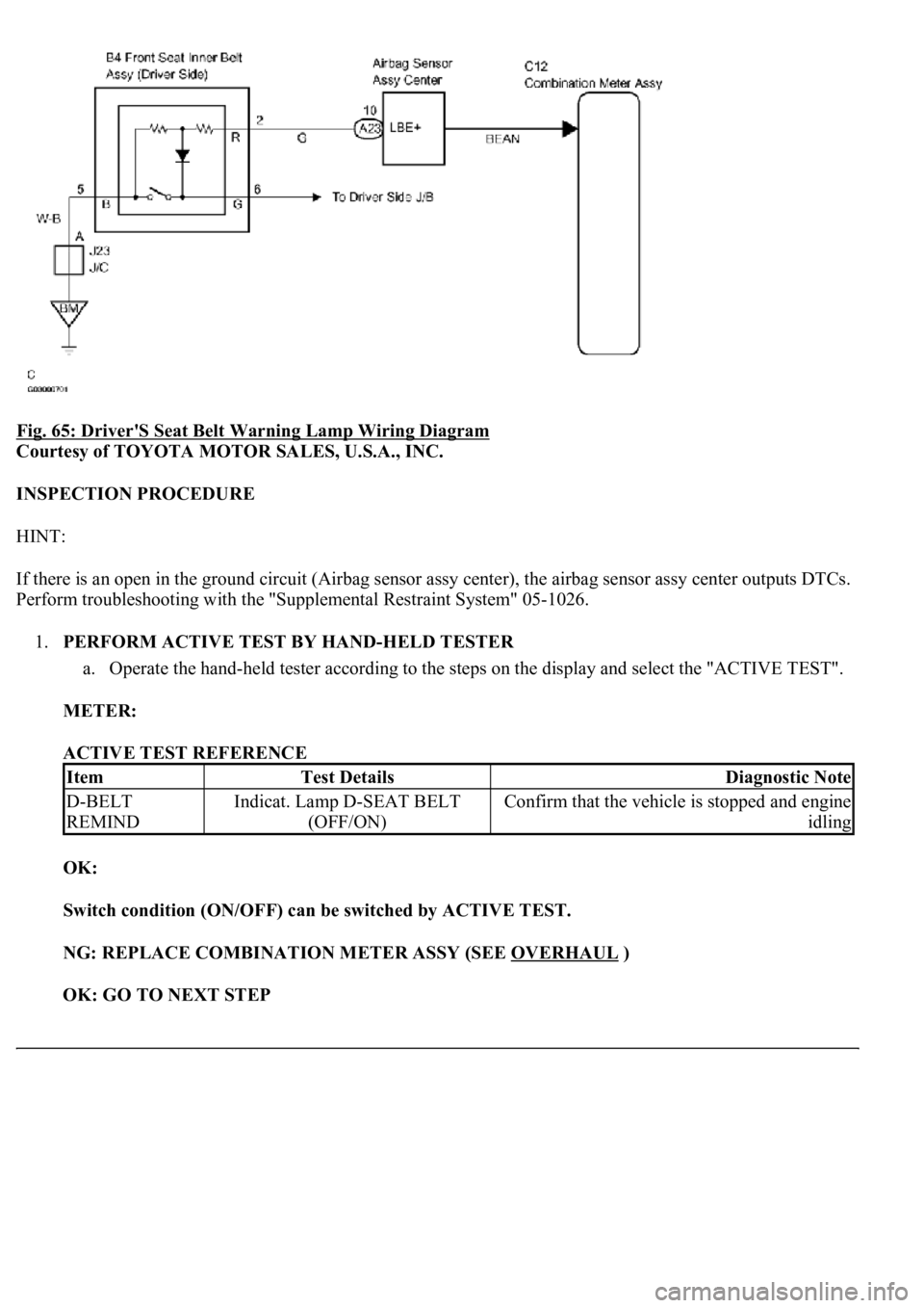
Fig. 65: Driver'S Seat Belt Warning Lamp Wiring Diagram
Courtesy of TOYOTA MOTOR SALES, U.S.A., INC.
INSPECTION PROCEDURE
HINT:
If there is an open in the ground circuit (Airbag sensor assy center), the airbag sensor assy center outputs DTCs.
Perform troubleshooting with the "Supplemental Restraint System" 05-1026.
1.PERFORM ACTIVE TEST BY HAND-HELD TESTER
a. Operate the hand-held tester according to the steps on the display and select the "ACTIVE TEST".
METER:
ACTIVE TEST REFERENCE
OK:
Switch condition (ON/OFF) can be switched by ACTIVE TEST.
NG: REPLACE COMBINATION METER ASSY (SEE OVERHAUL
)
OK: GO TO NEXT STEP
ItemTest DetailsDiagnostic Note
D-BELT
REMINDIndicat. Lamp D-SEAT BELT
(OFF/ON)Confirm that the vehicle is stopped and engine
idling