engine oil LEXUS LS430 2003 Factory Owner's Guide
[x] Cancel search | Manufacturer: LEXUS, Model Year: 2003, Model line: LS430, Model: LEXUS LS430 2003Pages: 4500, PDF Size: 87.45 MB
Page 3312 of 4500

Fig. 33: Exploded View Of Partial Engine Assy Components (15 Of 15)
Courtesy of TOYOTA MOTOR SALES, U.S.A., INC.
REPLACEMENT
1.WORK FOR PREVENTING GASOLINE FROM SPILLING OUT (See PRECAUTION
)
2.DISCONNECT BATTERY NEGATIVE TERMINAL
3.REMOVE HOOD SUB-ASSY (See OVERHAUL
)
4.REMOVE V-BANK COVER
5.REMOVE AIR CLEANER INLET NO.1
6.REMOVE INTAKE AIR CONNECTOR PIPE
7.REMOVE AIR CLEANER ASSY
8.REMOVE FRONT WHEEL
9.REMOVE ENGINE UNDER COVER NO.1
10.REMOVE ENGINE UNDER COVER NO.2
11.DRAIN ENGINE OIL
12.DRAIN ENGINE COOLANT
Page 3313 of 4500
13.DRAIN AUTOMATIC TRANSMISSION FLUID
14.REMOVE RADIATOR ASSY (See REPLACEMENT
)
15.DISCONNECT FUEL PIPE SUB-ASSY NO.2 (See REPLACEMENT
)
16.REMOVE FAN AND GENERATOR V BELT (See REPLACEMENT
)
17.DISCONNECT ENGINE WIRE
a. Disconnect the engine wire from the ECM box.
b. Remove the nut, and disconnect the generator wire from the generator.
c. Disconnect the wire for generator wire from the wire clamp on generator.
d. Remove the bolt, and disconnect the ground cable from the stay on the generator.
e. Remove the 2 bolts, and disconnect the PS oil hose from the No. 1 oil pan.
f. Remove the bolt, and disconnect the ground strap from the body.
18.DISCONNECT AIR HOSE NO.5
19.DISCONNECT FUEL VAPOR FEED HOSE NO.2
20.DISCONNECT HEATER WATER INLET HOSE A
21.DISCONNECT HEATER WATER OUTLET HOSE A (FROM HEATER UNIT)
22.DISCONNECT VANE PUMP OIL RESERVOIR ASSY
23.DISCONNECT VANE PUMP ASSY
a. Disconnect the 2 PS air hoses.
b. Remove the 2 screws and RH engine under cover.
c. Disconnect the PS oil pressure switch connector.
d. Remove the 2 bolts and nut, and disconnect the pump from the engine.
e. Support the pump securely.
24.DISCONNECT COOLER COMPRESSOR ASSY
a. Disconnect the compressor connector.
b. Disconnect the wire clamp from the wire bracket on the compressor.
c. Remove the bolt, nut and stay.
d. Remove the bolt, and disconnect the wire bracket from the compressor.
e. Remove the bolt, and disconnect the compressor from the engine.
f. Support the cooler compressor securely.
25.REMOVE FRONT FLOOR BRACE CENTER
a. Remove the 4 bolts and brace center.
26.REMOVE EXHAUST PIPE ASSY (See REPLACEMENT
)
27.REMOVE W/ CATALYST CONVERTER ASSY
28.REMOVE FRONT FLOOR HEAT INSULATOR NO.1
29.REMOVE PARKING BRAKE CABLE HEAT INSULATOR
30.REMOVE PROPELLER W/ CENTER BEARING SHAFT ASSY (See OVERHAUL
)
31.REMOVE FLOOR SHIFT GEAR SHIFTING ROD SUB-ASSY
32.REMOVE STEERING SLIDING W/ SHAFT YOKE SUB-ASSY
Page 3318 of 4500
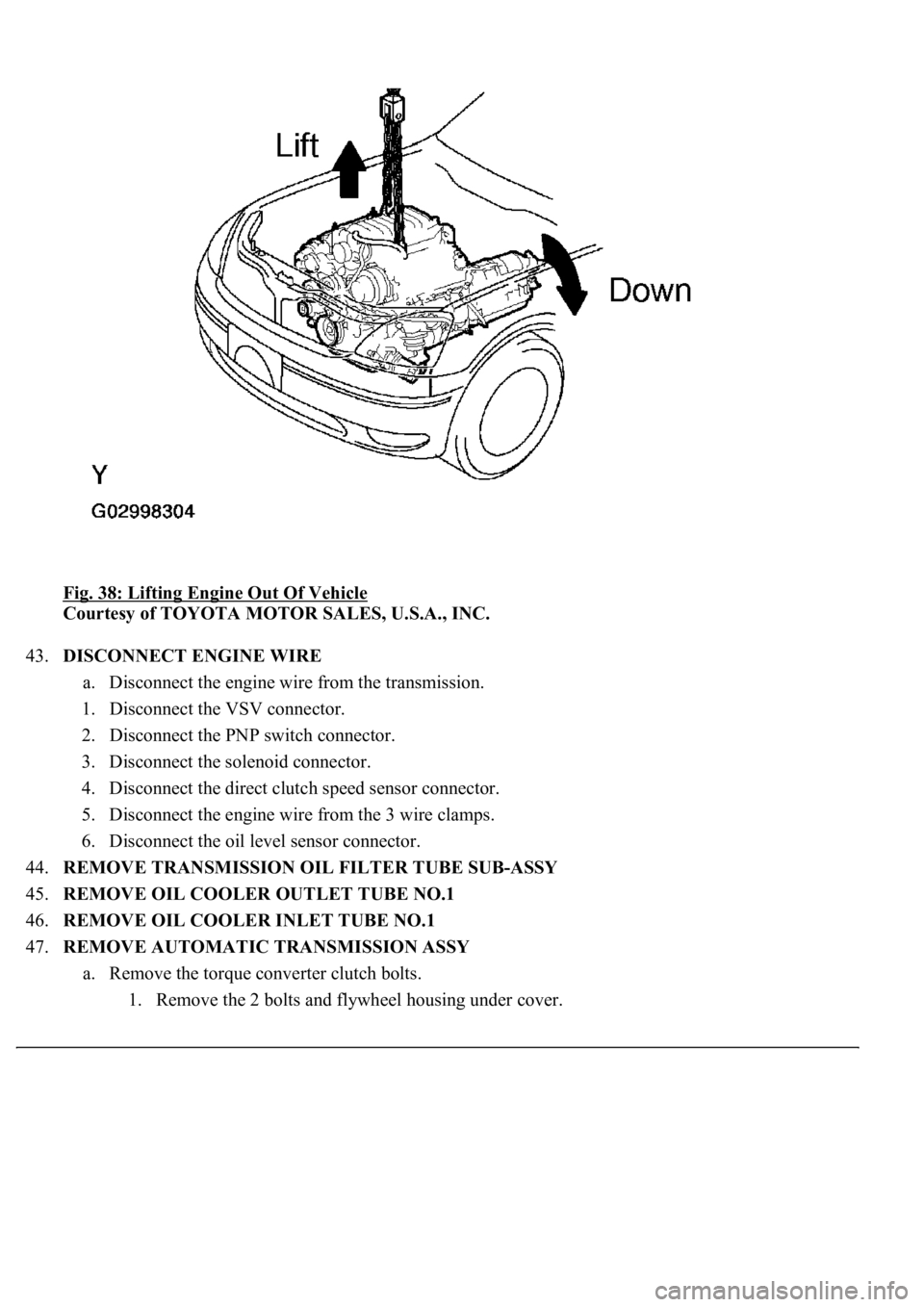
Fig. 38: Lifting Engine Out Of Vehicle
Courtesy of TOYOTA MOTOR SALES, U.S.A., INC.
43.DISCONNECT ENGINE WIRE
a. Disconnect the engine wire from the transmission.
1. Disconnect the VSV connector.
2. Disconnect the PNP switch connector.
3. Disconnect the solenoid connector.
4. Disconnect the direct clutch speed sensor connector.
5. Disconnect the engine wire from the 3 wire clamps.
6. Disconnect the oil level sensor connector.
44.REMOVE TRANSMISSION OIL FILTER TUBE SUB-ASSY
45.REMOVE OIL COOLER OUTLET TUBE NO.1
46.REMOVE OIL COOLER INLET TUBE NO.1
47.REMOVE AUTOMATIC TRANSMISSION ASSY
a. Remove the torque converter clutch bolts.
1. Remove the 2 bolts and fl
ywheel housing under cover.
Page 3328 of 4500
Fig. 48: Identifying Knock Sensor Connectors
Courtesy of TOYOTA MOTOR SALES, U.S.A., INC.
64.REMOVE ENGINE HANGER NO.1
65.REMOVE ENGINE HANGER NO.2
66.REMOVE IGNITION COIL ASSY
67.REMOVE OIL FILTER BRACKET SUB-ASSY
a. Disconnect the oil pressure switch connector.
b. Remove the stud bolt, 2 nuts and oil filter bracket with gasket.
68.REMOVE CRANKSHAFT POSITION SENSOR
69.REMOVE ENGINE OIL LEVEL SENSOR
70.REMOVE EXHAUST MANIFOLD HEAT INSULATOR NO.1
71.REMOVE EXHAUST MANIFOLD SUB-ASSY RH
a. Remove the 8 nuts, exhaust manifold and
gasket.
Page 3338 of 4500
Fig. 58: Installing Exhaust Manifold
Courtesy of TOYOTA MOTOR SALES, U.S.A., INC.
85.INSTALL EXHAUST MANIFOLD HEAT INSULATOR NO.1
86.INSTALL ENGINE OIL LEVEL SENSOR
87.INSTALL CRANKSHAFT POSITION SENSOR (See REPLACEMENT
)
88.INSTALL OIL FILTER BRACKET SUB-ASSY
Torque: 18 N.m (184 kgf.cm, 13 ft.lbf)
89.INSTALL IGNITION COIL ASSY
Torque: 7.5 N.m (77 kgf.cm, 66 in.lbf)
90.INSTALL ENGINE HANGER NO.2
Torque: 37 N.m (377 kgf.cm, 27 ft.lbf)
91.INSTALL ENGINE HANGER NO. 1
Torque: 37 N.m (377 kgf.cm, 27 ft.lbf)
92.INSTALL KNOCK SENSOR
a. Install the 2 knock sensors with the 2 nuts, as shown in the illustration.
Torque: 20 N.m (204 kgf.cm, 15 ft.lbf)
b. Connect the 2 knock sensor connectors.
Page 3352 of 4500
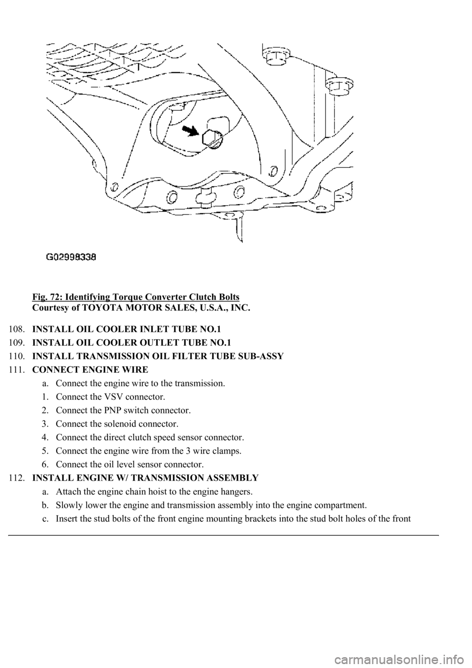
Fig. 72: Identifying Torque Converter Clutch Bolts
Courtesy of TOYOTA MOTOR SALES, U.S.A., INC.
108.INSTALL OIL COOLER INLET TUBE NO.1
109.INSTALL OIL COOLER OUTLET TUBE NO.1
110.INSTALL TRANSMISSION OIL FILTER TUBE SUB-ASSY
111.CONNECT ENGINE WIRE
a. Connect the engine wire to the transmission.
1. Connect the VSV connector.
2. Connect the PNP switch connector.
3. Connect the solenoid connector.
4. Connect the direct clutch speed sensor connector.
5. Connect the engine wire from the 3 wire clamps.
6. Connect the oil level sensor connector.
112.INSTALL ENGINE W/ TRANSMISSION ASSEMBLY
a. Attach the engine chain hoist to the engine hangers.
b. Slowly lower the engine and transmission assembly into the engine compartment.
c. Insert the stud bolts of the front en
gine mounting brackets into the stud bolt holes of the front
Page 3356 of 4500
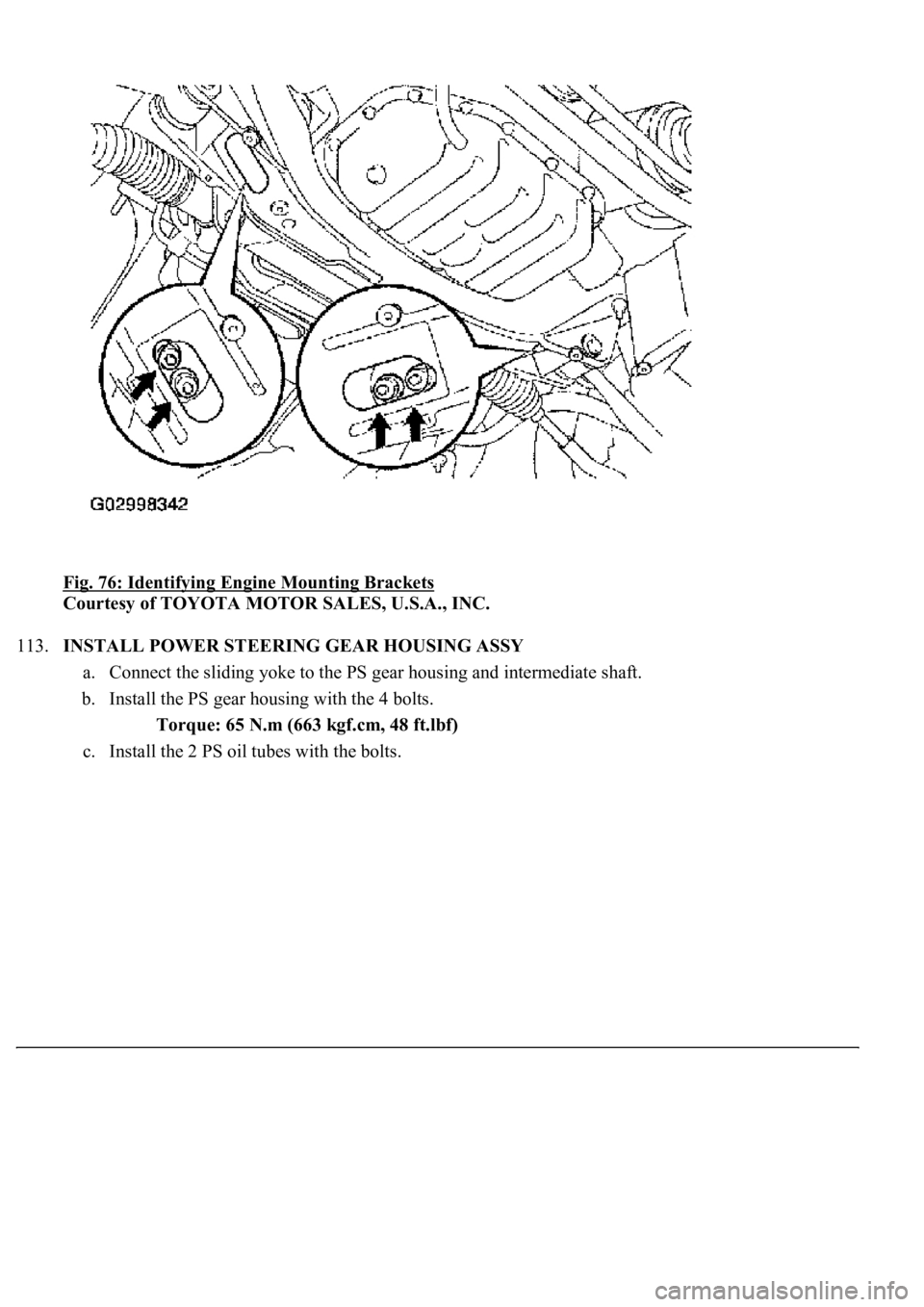
Fig. 76: Identifying Engine Mounting Brackets
Courtesy of TOYOTA MOTOR SALES, U.S.A., INC.
113.INSTALL POWER STEERING GEAR HOUSING ASSY
a. Connect the sliding yoke to the PS gear housing and intermediate shaft.
b. Install the PS gear housing with the 4 bolts.
Torque: 65 N.m (663 kgf.cm, 48 ft.lbf)
c. Install the 2 PS oil tubes with the bolts.
Page 3359 of 4500
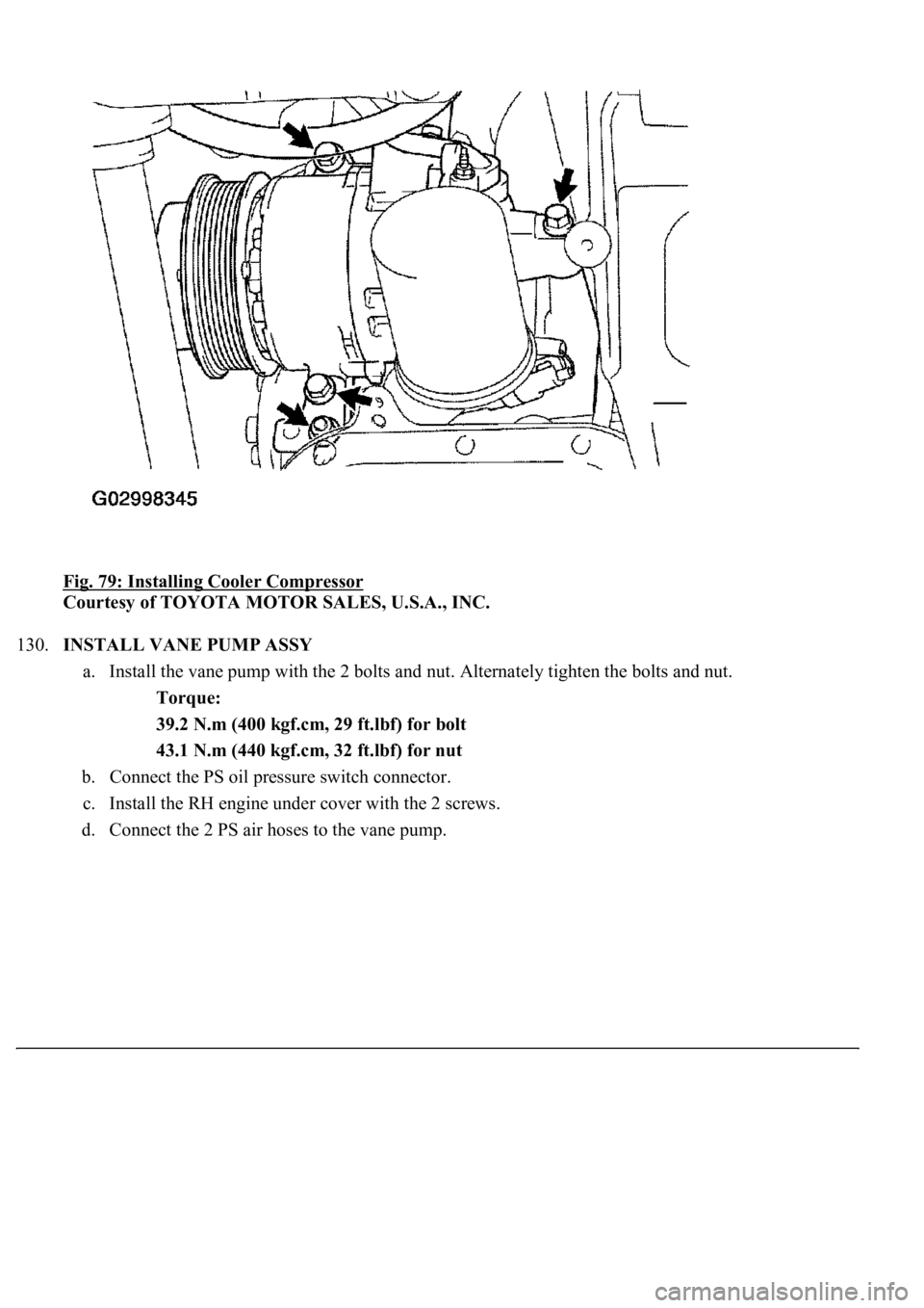
Fig. 79: Installing Cooler Compressor
Courtesy of TOYOTA MOTOR SALES, U.S.A., INC.
130.INSTALL VANE PUMP ASSY
a. Install the vane pump with the 2 bolts and nut. Alternately tighten the bolts and nut.
Torque:
39.2 N.m (400 kgf.cm, 29 ft.lbf) for bolt
43.1 N.m (440 kgf.cm, 32 ft.lbf) for nut
b. Connect the PS oil pressure switch connector.
c. Install the RH engine under cover with the 2 screws.
d. Connect the 2 PS air hoses to the vane pump.
Page 3360 of 4500
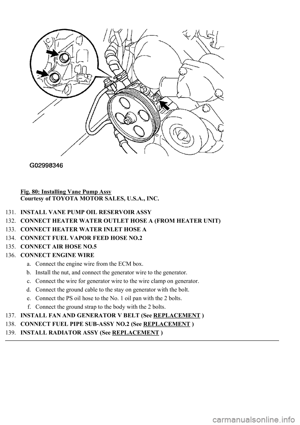
Fig. 80: Installing Vane Pump Assy
Courtesy of TOYOTA MOTOR SALES, U.S.A., INC.
131.INSTALL VANE PUMP OIL RESERVOIR ASSY
132.CONNECT HEATER WATER OUTLET HOSE A (FROM HEATER UNIT)
133.CONNECT HEATER WATER INLET HOSE A
134.CONNECT FUEL VAPOR FEED HOSE NO.2
135.CONNECT AIR HOSE NO.5
136.CONNECT ENGINE WIRE
a. Connect the engine wire from the ECM box.
b. Install the nut, and connect the generator wire to the generator.
c. Connect the wire for generator wire to the wire clamp on generator.
d. Connect the ground cable to the stay on generator with the bolt.
e. Connect the PS oil hose to the No. 1 oil pan with the 2 bolts.
f. Connect the ground strap to the body with the 2 bolts.
137.INSTALL FAN AND GENERATOR V BELT (See REPLACEMENT
)
138.CONNECT FUEL PIPE SUB-ASSY NO.2 (See REPLACEMENT
)
139.INSTALL RADIATOR ASSY (See REPLACEMENT
)
Page 3361 of 4500
140.INSTALL ENGINE UNDER COVER NO.2
141.INSTALL ENGINE UNDER COVER NO.1
142.INSTALL FRONT WHEEL
143.INSTALL AIR CLEANER ASSY
144.INSTALL INTAKE AIR CONNECTOR PIPE
145.INSTALL AIR CLEANER INLET NO.1
146.INSTALL V-BANK COVER
147.INSTALL HOOD SUB-ASSY (See ADJUSTMENT
and OVERHAUL )
148.CONNECT BATTERY NEGATIVE TERMINAL
149.ADD AUTOMATIC TRANSMISSION FLUID
150.ADD ENGINE COOLANT (See REPLACEMENT
)
151.ADD ENGINE OIL (See ON
-VEHICLE INSPECTION )
152.ADD POWER STEERING FLUID
153.BLEED POWER STEERING FLUID
154.INSPECT AUTOMATIC TRANSMISSION FLUID (See ADJUSTMENT
)
155.INSPECT ENGINE OIL LEAKS
156.CHECK FOR ENGINE COOLANT LEAKS
157.INSPECT FOR FUEL LEAKS
158.CHECK FOR EXHAUST GAS LEAKS
159.INSPECT AND ADJUST FRONT WHEEL ALIGNMENT
160.INSPECT IGNITION TIMING
161.INSPECT ENGINE IDLE SPEED
162.INSPECT CO/HC
163.ADJUST ENGINE (See INSPECTION
)
164.CHECK ABS SPEED SENSOR SIGNAL (See TEST MODE PROCEDURE
)
OVERHAUL
1.REMOVE SPARK PLUG
2.REMOVE OIL FILLER CAP SUB-ASSY
3.REMOVE CYLINDER HEAD COVER SUB-ASSY LH
a. Remove the 9 bolts, 9 seal washers, cylinder head cover and gasket.
4.REMOVE CYLINDER HEAD COVER SUB-ASSY
a. Remove the 9 bolts, 9 seal washers, c
ylinder head cover and gasket.