engine oil LEXUS LS430 2003 Factory Manual PDF
[x] Cancel search | Manufacturer: LEXUS, Model Year: 2003, Model line: LS430, Model: LEXUS LS430 2003Pages: 4500, PDF Size: 87.45 MB
Page 3753 of 4500
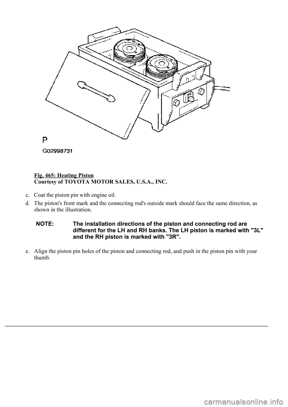
Fig. 465: Heating Piston
Courtesy of TOYOTA MOTOR SALES, U.S.A., INC.
c. Coat the piston pin with engine oil.
d. The piston's front mark and the connecting rod's outside mark should face the same direction, as
shown in the illustration.
e. Align the piston pin holes of the piston and connecting rod, and push in the piston pin with your
thumb.
Page 3766 of 4500
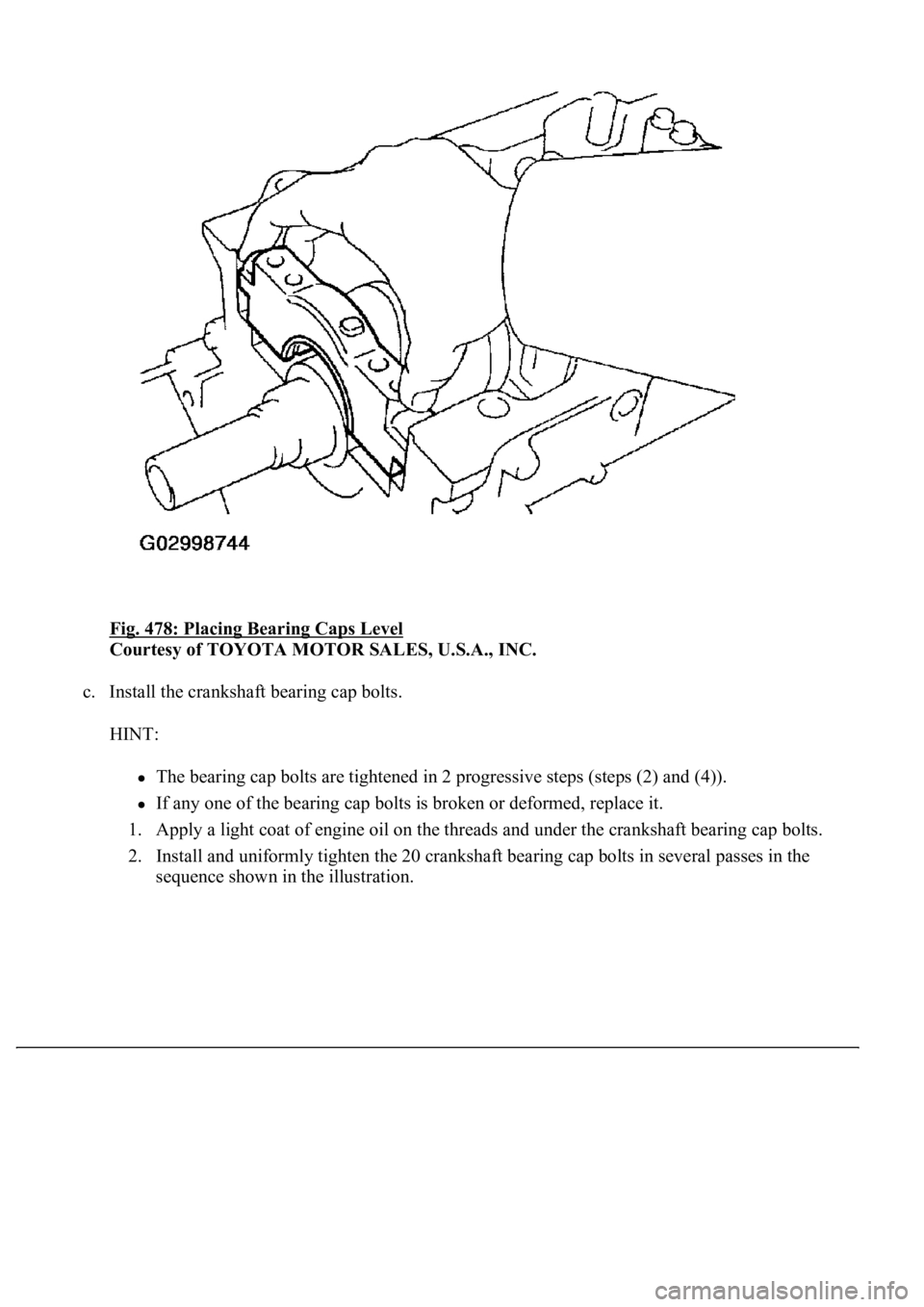
Fig. 478: Placing Bearing Caps Level
Courtesy of TOYOTA MOTOR SALES, U.S.A., INC.
c. Install the crankshaft bearing cap bolts.
HINT:
The bearing cap bolts are tightened in 2 progressive steps (steps (2) and (4)).
If any one of the bearing cap bolts is broken or deformed, replace it.
1. Apply a light coat of engine oil on the threads and under the crankshaft bearing cap bolts.
2. Install and uniformly tighten the 20 crankshaft bearing cap bolts in several passes in the
sequence shown in the illustration.
Page 3773 of 4500
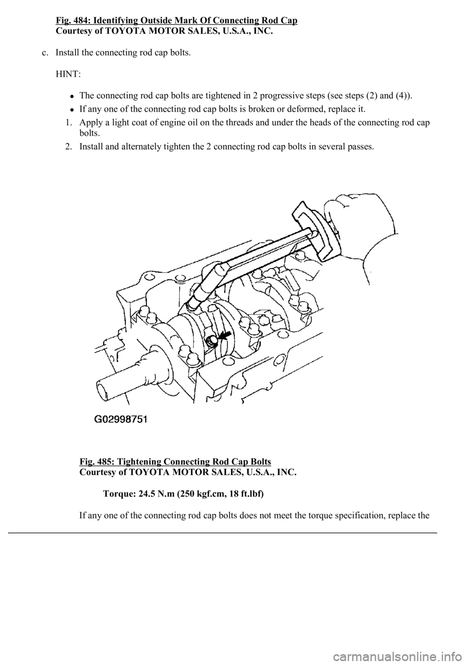
Fig. 484: Identifying Outside Mark Of Connecting Rod Cap
Courtesy of TOYOTA MOTOR SALES, U.S.A., INC.
c. Install the connecting rod cap bolts.
HINT:
The connecting rod cap bolts are tightened in 2 progressive steps (see steps (2) and (4)).
If any one of the connecting rod cap bolts is broken or deformed, replace it.
1. Apply a light coat of engine oil on the threads and under the heads of the connecting rod cap
bolts.
2. Install and alternately tighten the 2 connecting rod cap bolts in several passes.
Fig. 485: Tightening Connecting Rod Cap Bolts
Courtesy of TOYOTA MOTOR SALES, U.S.A., INC.
Torque: 24.5 N.m (250 kgf.cm, 18 ft.lbf)
If an
y one of the connecting rod cap bolts does not meet the torque specification, replace the
Page 4105 of 4500
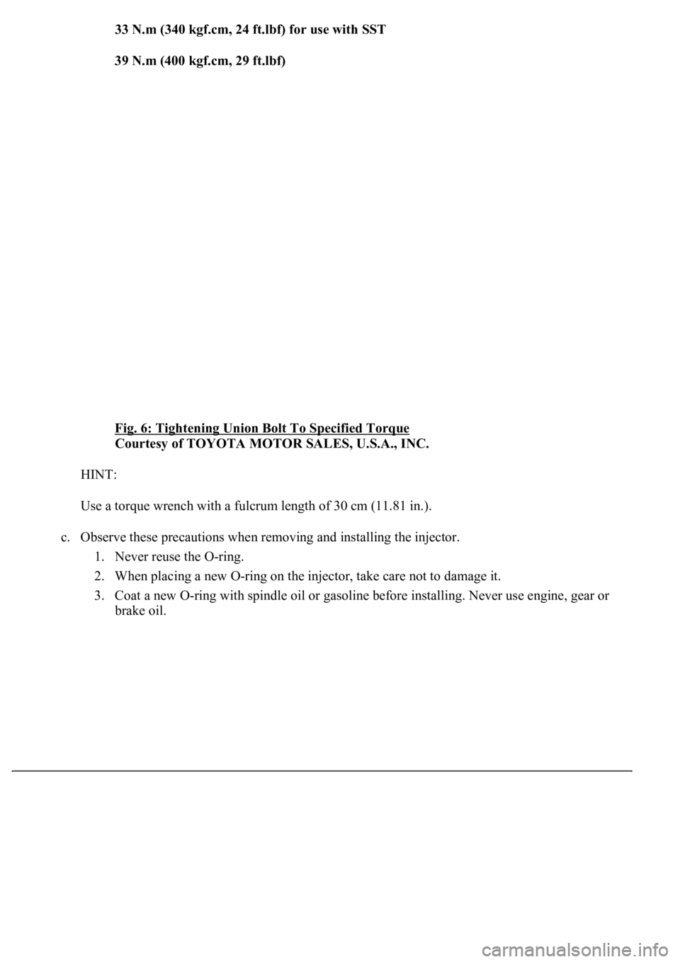
33 N.m (340 kgf.cm, 24 ft.lbf) for use with SST
39 N.m (400 kgf.cm, 29 ft.lbf)
Fig. 6: Tightening Union Bolt To Specified Torque
Courtesy of TOYOTA MOTOR SALES, U.S.A., INC.
HINT:
Use a torque wrench with a fulcrum length of 30 cm (11.81 in.).
c. Observe these precautions when removing and installing the injector.
1. Never reuse the O-ring.
2. When placing a new O-ring on the injector, take care not to damage it.
3. Coat a new O-ring with spindle oil or gasoline before installing. Never use engine, gear or
brake oil.
Page 4110 of 4500
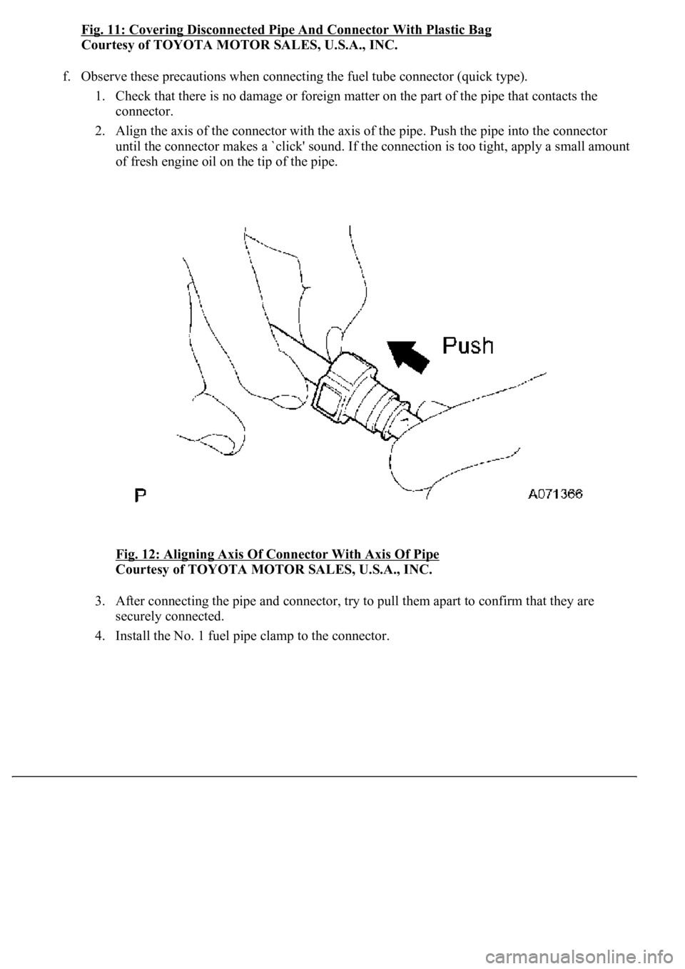
Fig. 11: Covering Disconnected Pipe And Connector With Plastic Bag
Courtesy of TOYOTA MOTOR SALES, U.S.A., INC.
f. Observe these precautions when connecting the fuel tube connector (quick type).
1. Check that there is no damage or foreign matter on the part of the pipe that contacts the
connector.
2. Align the axis of the connector with the axis of the pipe. Push the pipe into the connector
until the connector makes a `click' sound. If the connection is too tight, apply a small amount
of fresh engine oil on the tip of the pipe.
Fig. 12: Aligning Axis Of Connector With Axis Of Pipe
Courtesy of TOYOTA MOTOR SALES, U.S.A., INC.
3. After connecting the pipe and connector, try to pull them apart to confirm that they are
securely connected.
4. Install the No. 1 fuel pipe clamp to the connector.
Page 4209 of 4500
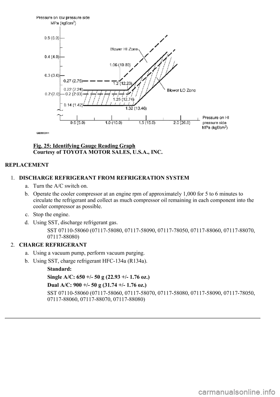
Fig. 25: Identifying Gauge Reading Graph
Courtesy of TOYOTA MOTOR SALES, U.S.A., INC.
REPLACEMENT
1.DISCHARGE REFRIGERANT FROM REFRIGERATION SYSTEM
a. Turn the A/C switch on.
b. Operate the cooler compressor at an engine rpm of approximately 1,000 for 5 to 6 minutes to
circulate the refrigerant and collect as much compressor oil remaining in each component into the
cooler compressor as possible.
c. Stop the engine.
d. Using SST, discharge refrigerant gas.
<00360036003700030013001a00140014001300100018001b0013001900130003000b0013001a00140014001a00100018001b0013001b0013000f00030013001a00140014001a00100018001b0013001c0013000f00030013001a00140014001a0010001a00
1b001300180013000f00030013001a00140014001a0010001b[8060, 07117-88070,
07117-88080)
2.CHARGE REFRIGERANT
a. Using a vacuum pump, perform vacuum purging.
b. Using SST, charge refrigerant HFC-134a (R134a).
Standard:
Single A/C: 650 +/- 50 g (22.93 +/- 1.76 oz.)
Dual A/C: 900 +/- 50 g (31.74 +/- 1.76 oz.)
<00360036003700030013001a00140014001300100018001b0013001900130003000b0013001a00140014001a00100018001b001300190013000f00030013001a00140014001a00100018001b0013001a0013000f00030013001a00140014001a0010001800
1b0013001b0013000f00030013001a00140014001a00100018[8090, 07117-78050,
07117-88060, 07117-88070, 07117-88080)
Page 4330 of 4500
6. Visually check if spark occurs while the engine is being cranked.
If a spark does not occur, perform the test as follows:
Fig. 4: Spark Test Flow Diagram
Courtesy of TOYOTA MOTOR SALES, U.S.A., INC.
7. Using a 16 mm (0.63 in.) plug wrench, install the spark plugs.
Torque: 18 N.m (180 kgf.cm, 13 ft.lbf)
8. Install the ignition coils (see REPLACEMENT
).
Page 4338 of 4500
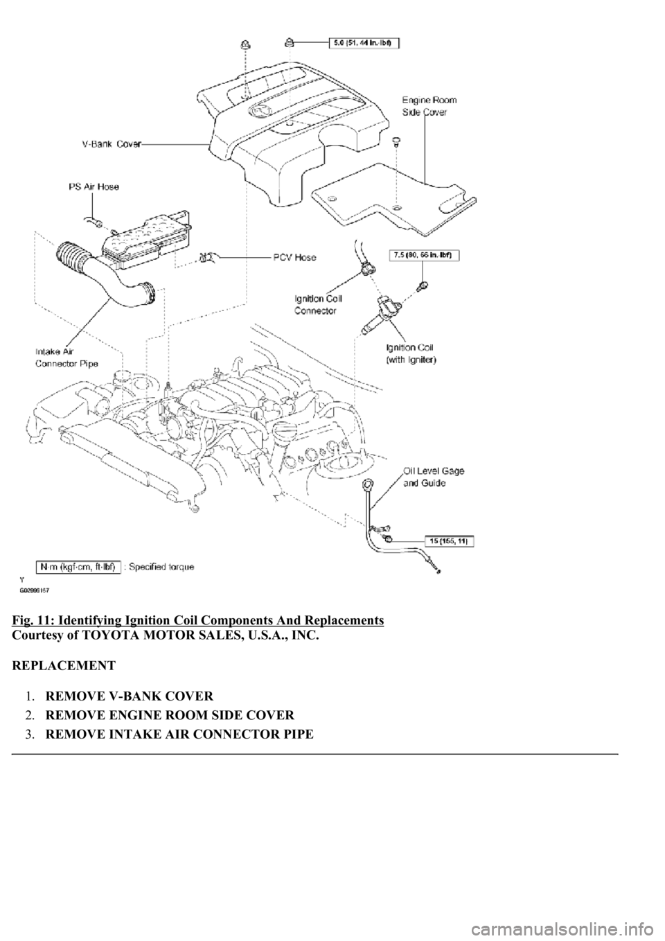
Fig. 11: Identifying Ignition Coil Components And Replacements
Courtesy of TOYOTA MOTOR SALES, U.S.A., INC.
REPLACEMENT
1.REMOVE V-BANK COVER
2.REMOVE ENGINE ROOM SIDE COVER
3.REMOVE INTAKE AIR CONNECTOR PIPE
Page 4339 of 4500
4.REMOVE OIL LEVEL GAGE SUB-ASSY (See step 8 in REPLACEMENT )
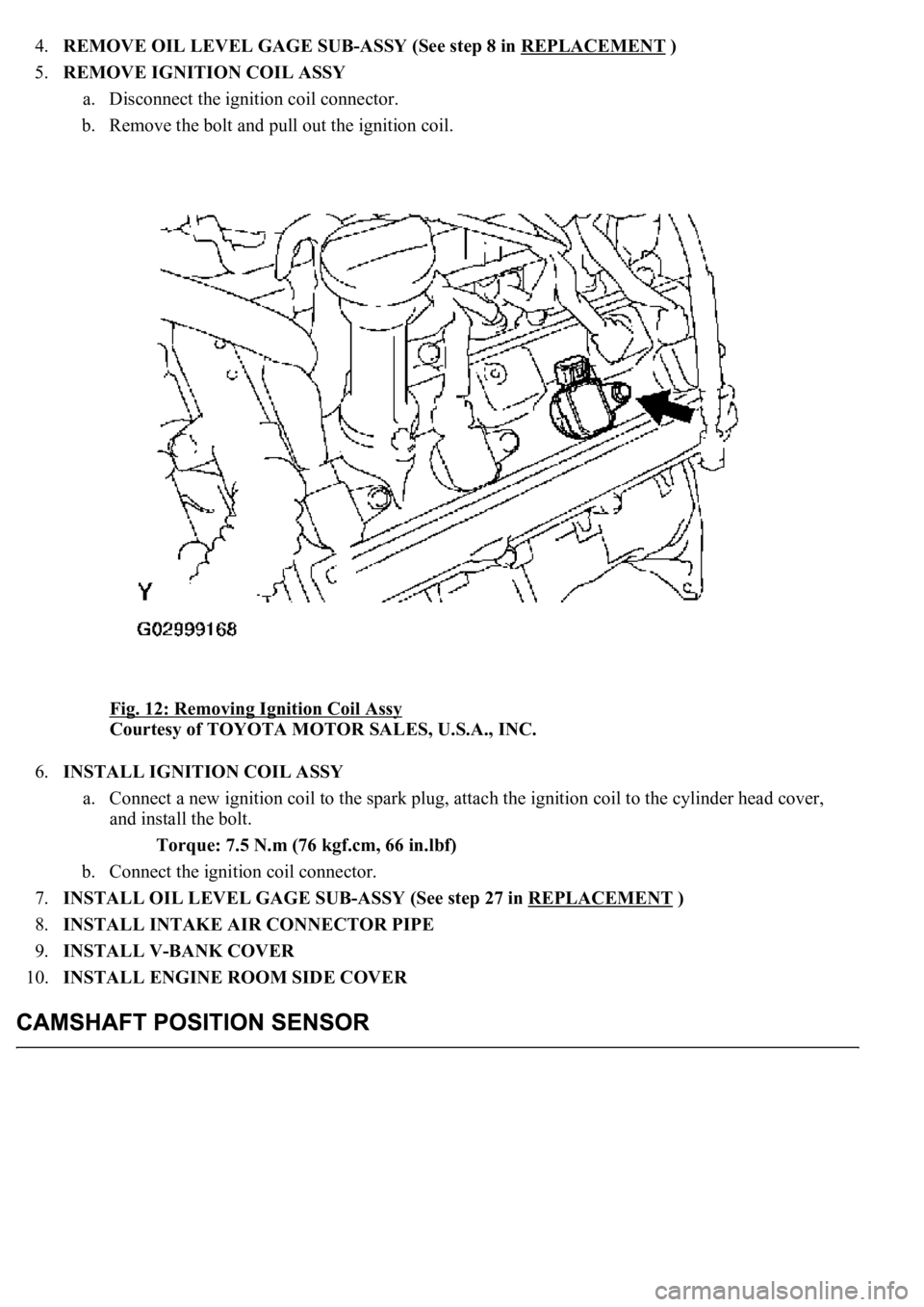
5.REMOVE IGNITION COIL ASSY
a. Disconnect the ignition coil connector.
b. Remove the bolt and pull out the ignition coil.
Fig. 12: Removing Ignition Coil Assy
Courtesy of TOYOTA MOTOR SALES, U.S.A., INC.
6.INSTALL IGNITION COIL ASSY
a. Connect a new ignition coil to the spark plug, attach the ignition coil to the cylinder head cover,
and install the bolt.
Torque: 7.5 N.m (76 kgf.cm, 66 in.lbf)
b. Connect the ignition coil connector.
7.INSTALL OIL LEVEL GAGE SUB-ASSY (See step 27 in REPLACEMENT
)
8.INSTALL INTAKE AIR CONNECTOR PIPE
9.INSTALL V-BANK COVER
10.INSTALL ENGINE ROOM SIDE COVER