wheel LEXUS LS430 2003 Factory Owner's Manual
[x] Cancel search | Manufacturer: LEXUS, Model Year: 2003, Model line: LS430, Model: LEXUS LS430 2003Pages: 4500, PDF Size: 87.45 MB
Page 76 of 4500
NG: Go to step 4
OK: Go to next step
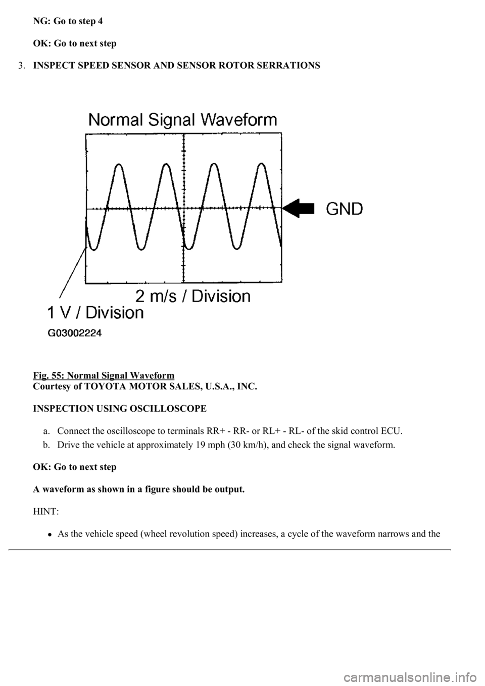
3.INSPECT SPEED SENSOR AND SENSOR ROTOR SERRATIONS
Fig. 55: Normal Signal Waveform
Courtesy of TOYOTA MOTOR SALES, U.S.A., INC.
INSPECTION USING OSCILLOSCOPE
a. Connect the oscilloscope to terminals RR+ - RR- or RL+ - RL- of the skid control ECU.
b. Drive the vehicle at approximately 19 mph (30 km/h), and check the signal waveform.
OK: Go to next step
A waveform as shown in a figure should be output.
HINT:
As the vehicle speed (wheel revolution speed) increases, a cycle of the waveform narrows and the
Page 81 of 4500
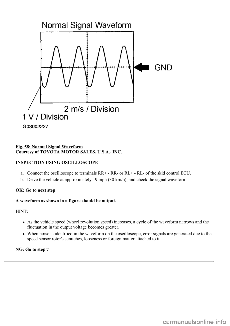
Fig. 58: Normal Signal Waveform
Courtesy of TOYOTA MOTOR SALES, U.S.A., INC.
INSPECTION USING OSCILLOSCOPE
a. Connect the oscilloscope to terminals RR+ - RR- or RL+ - RL- of the skid control ECU.
b. Drive the vehicle at approximately 19 mph (30 km/h), and check the signal waveform.
OK: Go to next step
A waveform as shown in a figure should be output.
HINT:
As the vehicle speed (wheel revolution speed) increases, a cycle of the waveform narrows and the
fluctuation in the output voltage becomes greater.
When noise is identified in the waveform on the oscilloscope, error signals are generated due to the
speed sensor rotor's scratches, looseness or foreign matter attached to it.
NG: Go to step 7
Page 83 of 4500
NG: REPLACE REAR SPEED SENSOR
OK: REPLACE ABS & TRACTION ACTUATOR ASSY (SEE REPLACEMENT
)
CIRCUIT DESCRIPTION
<0037004b004c0056000300560052004f004800510052004c00470003005700580055005100560003005200510003005a004b0048005100030056004c004a00510044004f0056000300440055004800030055004800460048004c0059004800470003004900
550052005000030057004b0048000300280026003800030044[nd controls the pressure acting on the wheel
c
ylinders to control the braking force.
Page 108 of 4500
When U0121/94, U0123/62, U0124/95 or U0126/63 are output together with C1231/31, inspect and
repair the trouble areas indicated by U0121/94, U0123/62, U0124/95 or U0126/63 first.
When the speed sensor or the yaw rate sensor has trouble, DTCs for the steering angle sensor may be
output even when the steering angle sensor is normal. When DTCs for the speed sensor or yaw rate
sensor are output together with other DTCs for the steering angle sensor, inspect and repair the speed
sensor and yaw rate sensor first, and then inspect and repair the steering angle sensor.
1.CHECK HARNESS AND CONNECTOR (MOMENTARY INTERRUPTION)
a. Using the hand-held tester, check for any momentary interruption in the wire harness and
connectors between the skid control ECU and steering angle sensor (see CHECK FOR
INTERMITTENT PROBLEMS ).
MEASUREMENT ITEM / RANGE (DISPLAY) DESCRIPTION
OK: Go to next step
There are no momentary interruptions.
NG: REPAIR OR REPLACE HARNESS OR CONNECTOR (SKID CONTROL ECU -
STEERING ANGLE SENSOR)
OK: Go to next step
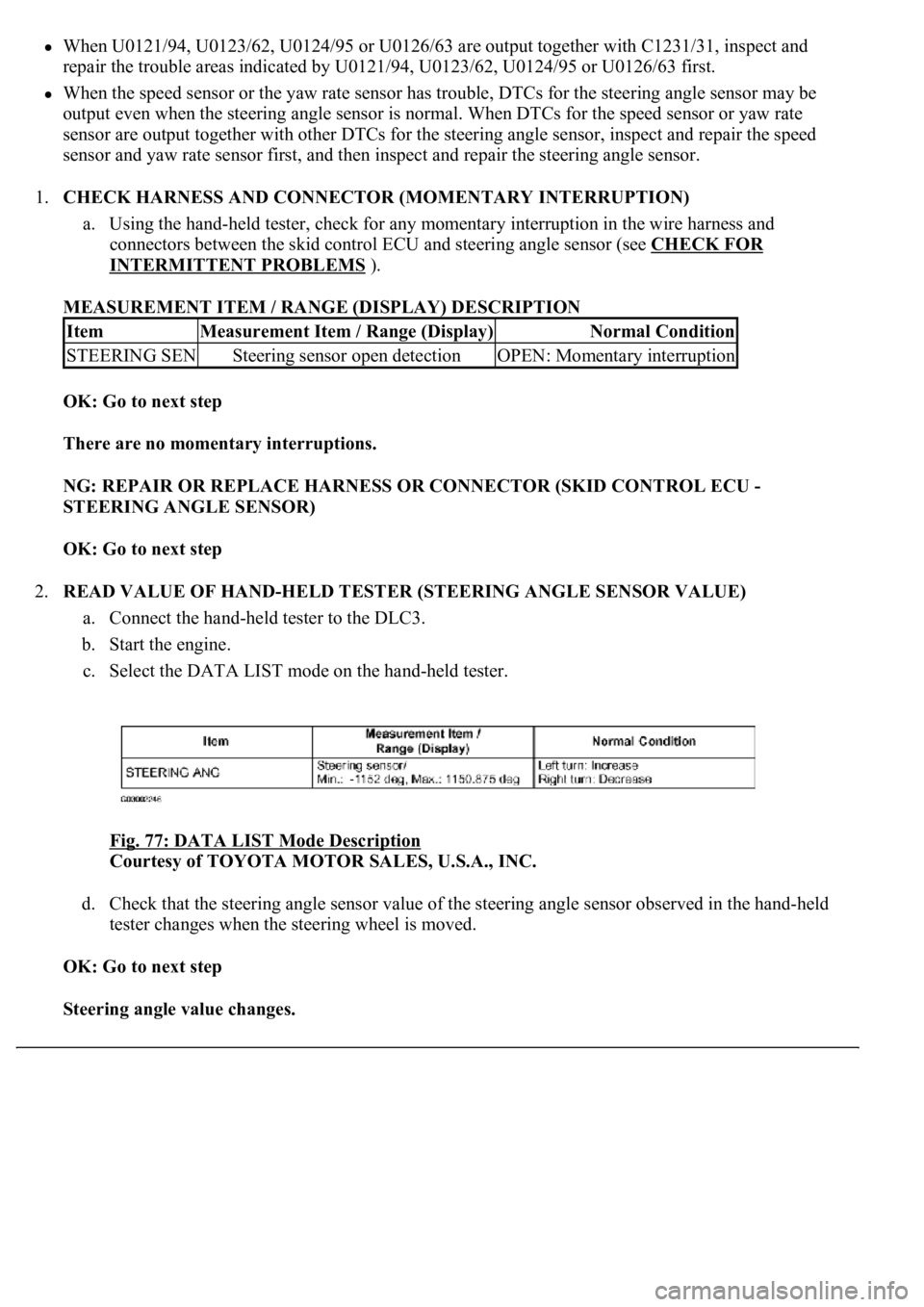
2.READ VALUE OF HAND-HELD TESTER (STEERING ANGLE SENSOR VALUE)
a. Connect the hand-held tester to the DLC3.
b. Start the engine.
c. Select the DATA LIST mode on the hand-held tester.
Fig. 77: DATA LIST Mode Description
Courtesy of TOYOTA MOTOR SALES, U.S.A., INC.
d. Check that the steering angle sensor value of the steering angle sensor observed in the hand-held
tester changes when the steering wheel is moved.
OK: Go to next step
Steering angle value changes.
ItemMeasurement Item / Range (Display)Normal Condition
STEERING SENSteering sensor open detectionOPEN: Momentary interruption
Page 109 of 4500
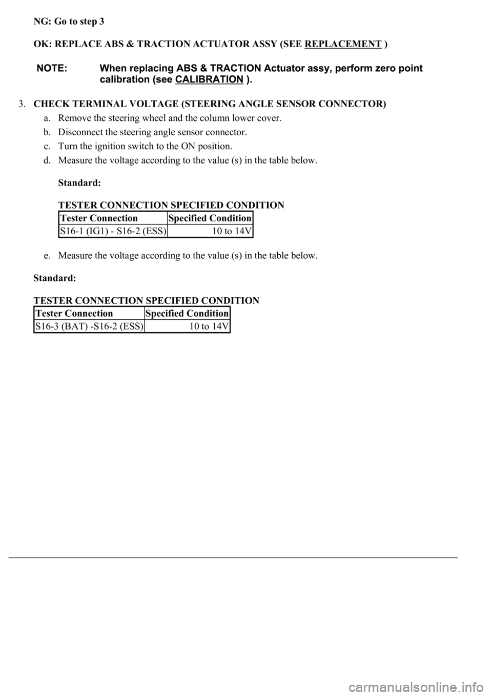
NG: Go to step 3
OK: REPLACE ABS & TRACTION ACTUATOR ASSY (SEE REPLACEMENT
)
3.CHECK TERMINAL VOLTAGE (STEERING ANGLE SENSOR CONNECTOR)
a. Remove the steering wheel and the column lower cover.
b. Disconnect the steering angle sensor connector.
c. Turn the ignition switch to the ON position.
d. Measure the voltage according to the value (s) in the table below.
Standard:
TESTER CONNECTION SPECIFIED CONDITION
e. Measure the voltage according to the value (s) in the table below.
Standard:
TESTER CONNECTION SPECIFIED CONDITION
Tester ConnectionSpecified Condition
S16-1 (IG1) - S16-2 (ESS)10 to 14V
Tester ConnectionSpecified Condition
S16-3 (BAT) -S16-2 (ESS)10 to 14V
Page 116 of 4500
CIRCUIT DESCRIPTION
The speed sensor detects wheel speed and sends the appropriate signals to the ECU. These signals are used to
control the ABS control system. The front and rear rotors have 48 serrations each.
When the rotors rotate, the magnetic field emitted by the permanent magnet in the speed sensor generates an
AC voltage. Since the frequency of this AC voltage changes in direct proportion to the speed of the rotor, the
frequenc
y is used by the ECU to detect the speed of each wheel.
Page 118 of 4500
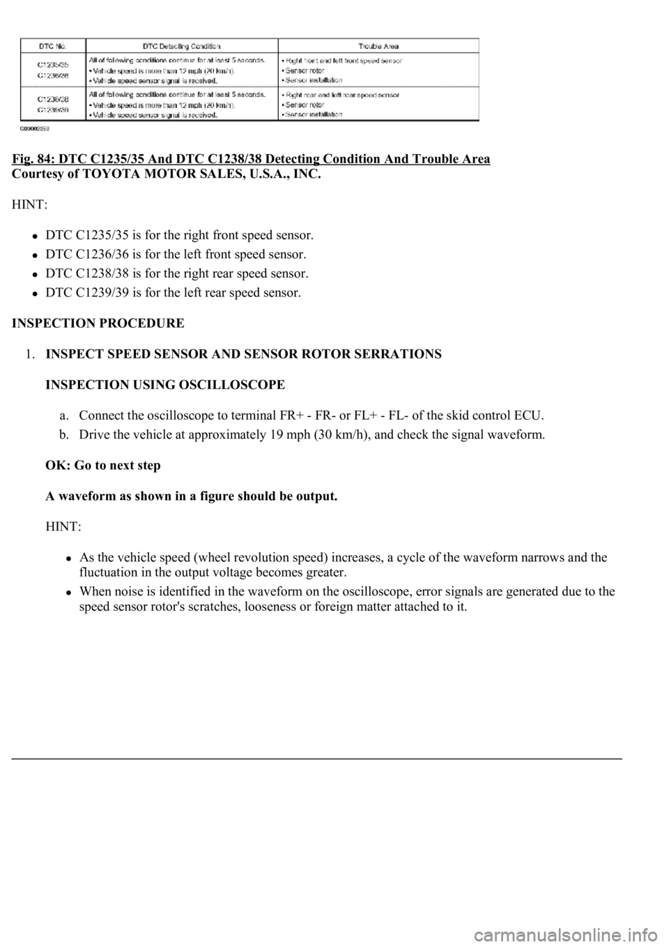
Fig. 84: DTC C1235/35 And DTC C1238/38 Detecting Condition And Trouble Area
Courtesy of TOYOTA MOTOR SALES, U.S.A., INC.
HINT:
DTC C1235/35 is for the right front speed sensor.
DTC C1236/36 is for the left front speed sensor.
DTC C1238/38 is for the right rear speed sensor.
DTC C1239/39 is for the left rear speed sensor.
INSPECTION PROCEDURE
1.INSPECT SPEED SENSOR AND SENSOR ROTOR SERRATIONS
INSPECTION USING OSCILLOSCOPE
a. Connect the oscilloscope to terminal FR+ - FR- or FL+ - FL- of the skid control ECU.
b. Drive the vehicle at approximately 19 mph (30 km/h), and check the signal waveform.
OK: Go to next step
A waveform as shown in a figure should be output.
HINT:
As the vehicle speed (wheel revolution speed) increases, a cycle of the waveform narrows and the
fluctuation in the output voltage becomes greater.
When noise is identified in the waveform on the oscilloscope, error signals are generated due to the
speed sensor rotor's scratches, looseness or forei
gn matter attached to it.
Page 172 of 4500
8.INSPECT PAD WEAR INDICATOR WIRE ASSY
FRONT:
HINT:
Check that there are no scratches or cracks on the pad wear indicator.
a. Remove the front wheel RH.
b. Disconnect front pad wear indicator connector.
c. Measure the resistance accordin
g to the value (s) in the table below.
Page 174 of 4500

Fig. 126: Inspecting Pad Wear Indicator Wire Assy
Courtesy of TOYOTA MOTOR SALES, U.S.A., INC.
Standard:
TESTER CONNECTION SPECIFIED CONDITION
REAR:
HINT:
Check that there are no scratches or cracks on the pad wear indicator.
a. Remove the rear wheel RH.
b. Disconnect the pad wear indicator connector.
c. Measure the resistance according to the value (s) in the table below.
Standard:
TESTER CONNECTION SPECIFIED CONDITION
NG: REPLACE PAD WEAR INDICATOR WIRE ASSY
OK: REPLACE ABS & TRACTION ACTUATOR ASSY (SEE REPLACEMENT
)
CIRCUIT DESCRIPTION
The skid control ECU detects the TRAC control main switch ON/OFF signal and turns the TRAC OFF light
on/off.
When the TRAC control switch is pressed, the TRAC control does not operate and the TRAC OFF light comes
on.
The skid control ECU connected to the combination meter via CAN and MPX communications.
Tester ConnectionSpecified Condition
Terminal a - Terminal bBelow 1 ohms
Terminal a - Body ground1 Mohms or higher
Tester ConnectionSpecified Condition
Terminal a - Terminal bBelow 1 ohms
Terminal a - Body ground1 Mohms or higher
Page 469 of 4500
If the vehicle is raised with its engine running, connect terminals OPB and CG of the DLC3 to stop
the vehicle height control operation of the suspension control ECU.
Do not operate the steering wheel if there is no air in the pneumatic cylinder.
HINT:
The pneumatic cylinder could be damaged if twisted without air in the cylinder.
In the case of lifting down the vehicle without air in the cylinder, make sure all the pipes are securely
connected.
HINT:
The pneumatic cylinder could be damaged if any pipe is disconnected while lifting down the vehicle.
Do not apply battery voltage to the compressor motor for more than 60 seconds to prevent damage to the
motor.
HINT:
When it is necessary to perform the operation by charging the battery for more than 60 seconds, for example
height recovery without air in the cylinder, proceed to the operation as follows: after 60 seconds have passed,
turn the ignition switch off once, and then turn the ignition switch to the ON position again for commencement
of operation.