sensor LEXUS LS430 2003 Factory Repair Manual
[x] Cancel search | Manufacturer: LEXUS, Model Year: 2003, Model line: LS430, Model: LEXUS LS430 2003Pages: 4500, PDF Size: 87.45 MB
Page 1582 of 4500
Fig. 69: Identifying Clearance Warning ECU Assy Terminals
Courtesy of TOYOTA MOTOR SALES, U.S.A., INC.
NG: REPAIR OR REPLACE HARNESS OR CONNECTOR
OK: Go To Next Step.
3.REPLACE CLEARANCE WARNING BUZZER NO.1
a. Replace clearance warning buzzer No.1 with a new one.
b. Check clearance warning buzzer No.1.
Perform ACTIVE TEST following the same procedure as for step 1.
OK: Malfunction disappears (Clearance warning buzzer No.1 sounds).
OK: NORMAL
NG: PROCEED TO NEXT CIRCUIT INSPECTION SHOWN IN PROBLEM SYMPTOMS
TABLE
CIRCUIT DESCRIPTION
The clearance warning ECU assy receives the ultrasonic sensor signal to sound the clearance warning buzzer.
WIRING DIAGRAM
Page 1595 of 4500

Fig. 8: Identifying Terminals Of Climate Control ECU - LH (FR)
Courtesy of TOYOTA MOTOR SALES, U.S.A., INC.
a. Disconnect the C20 and S48 blower connectors.
b. Measure the voltage and resistance of the wire harness side connectors.
Standard:
TERMINAL DESCRIPTION AND SPECIFIED CONDITION
Symbols
(Terminal
No.)Wiring
ColorTerminal
DescriptionConditionSpecified
Condition
E (C20 - 8) -
Body groundW-B -
Body
ground
GroundAlwaysBelow 1 ohms
IG (C20 -7) -
Body groundB - Body
groundPower sourceIgnition switch ON10 to 14 V
V5 (C20 - 13)
- VG (C20 - 9)GR-R - LPower supply for
volume switchAlways5 kohms
VS (C20 - 12)
- VG (20 - 9)R-B - LVolume switch signalTurn volume switch: Max0 ohms --> 5
kohms
TB5 (C20 - 4)
- TBS (20 - 3)L-Y -
BR-WSeatback temperature
sensorSeatback temperature: 10°C --
> 30°C (50°F --> 86°F)Approx. 3.7
kohms -->
Approx. 1.7
Page 1596 of 4500

HINT:
*1: For vehicles with a rear seat heater system
*2: For vehicles with a rear seat climate control system
If the result is not as specified, there may be a malfunction on the wire harness side.
c. Reconnect the C20 and S48 blower connectors.
d. Measure the voltage of the connectors.
Standard:
TERMINAL DESCRIPTION AND SPECIFIED CONDITION
If the result is not as specified, the ECU ma
y have a malfunction.
kohms
TC5 (S48 - 2)
- TCS (S48 -
1)
B - BSeat cushion
temperature sensorSeatback temperature: 10°C --
> 30°C (50°F --> 86°F)
Approx. 3.7
kohms -->
Approx. 1.7
kohms
DSID (C20 -
6) - Body
groundP - Body
ground
Rear seat heater
switch*1 Rear seat
climate control
switch*2Ignition switch: ON Turn rear
seat heater switch*1 or rear
seat climate control switch*2
OFF --> ON
0 V --> 10 to 14
V
Symbols
(Terminal No.)Wiring
ColorTerminal DescriptionConditionSpecified
Condition
IND (C20-5) -
Body groundY-R - Body
groundClimate control switch
indicatorIgnition switch: ON Turn
climate control switch: OFF -->
ON0 V --> 10 to
14 V
IDL (C20-10) -
Body groundW - Body
groundEngine idle-up signal
Ignition switch: ON Turn
climate control switch: OFF -->
ON10 to 14 V --
> 0 V
TDB+ (C20-14) -
Body groundLG-B -
Body
groundPower supply for seatback
Peltier element (WARM)Ignition switch: ON Turn
climate control switch: OFF -->
Max. WARM0 V --> 10 to
14 V
TDB- (C20-1) -
Body groundB - Body
groundPower supply for seatback
Peltier element (COOL)Ignition switch: ON Turn
climate control switch: OFF -->
Max. COOL0 V --> 10 to
14 V
TDC+ (S48-3) -
Body groundL - Body
groundPower supply for seat
cushion Peltier element
(WARM)Ignition switch: ON Turn
climate control switch: OFF -->
Max. WARM0 V --> 10 to
14 V
TDC- (S48-6) -
Body groundY - Body
groundPower supply for seat
cushion Peltier element
(COOL)Ignition switch: ON Turn
climate control switch: OFF -->
Max. COOL0 V --> 10 to
14 V
Page 1598 of 4500

HINT:
*1: For vehicles with a rear seat heater system
*2: For vehicles with a rear seat climate control system
If the result is not as specified, there may be a malfunction on the wire harness side.
c. Reconnect the C21 and S49 blower connectors.
d. Measure the voltage of the connector.
Standard:
TERMINAL DESCRIPTION AND SPECIFIED CONDITION
If the result is not as specified, the ECU may have a malfunction.
3.SEAT CLIMATE CONTROL BLOWER LH (RR) (CLIMATE CONTROL ECU)
TBS (C21-3)G-Y - Rsensor30°C (50°F --> 86°F)Approx. 1.7
kohms
TC5 (S49-2) -
TCS (S49-1)B -BSeat cushion
temperature sensorTurn the volume switch: 10°C
--> 30°C (50°F --> 86°F)
Approx. 3.7
kohms -->
Approx. 1.7
kohms
DSID (C21-6)
- Body groundGR -
Body
groundRear seat heater
switch*1 Rear seat
climate control
switch*2Ignition switch: ON Turn rear
seat heater switch*1 or rear
seat climate control switch*2
OFF --> ON
0 V --> 10 to 14
V
Symbols
(Terminal No.)Wiring
ColorTerminal DescriptionConditionSpecified
Condition
IND (C21-5) -
Body groundY-B - Body
groundClimate control switch
indicatorIgnition switch: ON Turn
climate control switch: OFF -->
ON0 V --> 10 to
14 V
TDB+ (C21-14) -
Body groundLG-B -
Body
groundPower supply for seatback
Peltier element (WARM)Ignition switch: ON Turn
climate control switch: OFF -->
Max. WARM0 V --> 10 to
14 V
TDB- (C21-1) -
Body groundB - Body
groundPower supply for seatback
Peltier element (COOL)Ignition switch: ON Turn
climate control switch: OFF -->
Max. COOL0 V --> 10 to
14 V
TDC+ (S49-3) -
Body groundL - Body
groundPower supply for seat
cushion Peltier element
(WARM)Ignition switch: ON Turn
climate control switch: OFF -->
Max. WARM0 V --> 10 to
14 V
TDC- (S49-6) -
Body groundY - Body
groundPower supply for seat
cushion Peltier element
(COOL)Ignition switch: ON Turn
climate control switch: OFF -->
Max. COOL0 V --> 10 to
14 V
Page 1599 of 4500

Fig. 10: Identifying Terminals Of Climate Control ECU - LH (RR)
Courtesy of TOYOTA MOTOR SALES, U.S.A., INC.
a. Disconnect the C27 and C28 blower connectors.
b. Measure the voltage and resistance of the wire harness side connectors.
Standard:
TERMINAL DESCRIPTION AND SPECIFIED CONDITION
If the result is not as specified, there ma
y be a malfunction on the wire harness side.
Symbols
(Terminal No.)Wiring
ColorTerminal
DescriptionConditionSpecified Condition
GND (C27-11) -
Body groundW-B -
Body
ground
GroundAlwaysBelow 1 ohms
IG (C27-10) -
Body groundR-B - Body
groundPower sourceIgnition switch ON10 to 14 V
SW (C27-8) -
Body groundL - Body
groundClimate control
switchTurn the climate control
switch ONBelow 1 ohms
V5 (C27-18) -
VG (C27-16)Y-R - PVolume switchAlways5 kohms
VS (C27-17) -
VG (C27-16)GR-R - PVolume switch
signalRear left volume switch:
Max. COOL --> Max.
WARM
0 ohms --> 5 kohms
TB5 (C28-7) -
TBS (C28-16)G-Y - RSeatback
temperatureSeatback temperature: 10°
C --> 30°C (50°F --> 86°F)Approx. 3.7 kohms -
-> Approx. 1.7
kohms
H5 (C28-5) - HS
(C28-14)L-B - Y-RSeat cushion
temperature sensorSeat cushion temperature:
10°C --> 30°C (50°F -->
86°F)Approx. 3.7 kohms -
-> Approx. 1.7
kohms
TC5 (C28-6) -
TCS (C28-15)BR-R - P-
BHeater
temperature sensorHeater temperature: 10°C -
-> 30°C (50°F --> 86°F)Approx. 3.7 kohms -
-> Approx. 1.7
kohms
Page 1602 of 4500
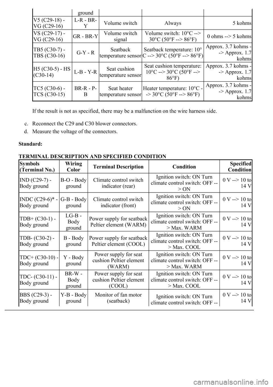
If the result is not as specified, there may be a malfunction on the wire harness side.
c. Reconnect the C29 and C30 blower connectors.
d. Measure the voltage of the connectors.
Standard:
TERMINAL DESCRIPTION AND SPECIFIED CONDITION
ground
V5 (C29-18) -
VG (C29-16)L-R - BR-
YVolume switchAlways5 kohms
VS (C29-17) -
VG (C29-16)GR - BR-YVolume switch
signalVolume switch: 10°C -->
30°C (50°F --> 86°F)0 ohms --> 5 kohms
TB5 (C30-7) -
TBS (C30-16)G-Y - RSeatback
temperature sensorSeatback temperature: 10°
C --> 30°C (50°F --> 86°F)Approx. 3.7 kohms -
-> Approx. 1.7
kohms
H5 (C30-5) - HS
(C30-14)L-B - Y-RSeat cushion
temperature sensorSeat cushion temperature:
10°C --> 30°C (50°F -->
86°F)Approx. 3.7 kohms -
-> Approx. 1.7
kohms
TC5 (C30-6) -
TCS (C30-15)BR-R - P-
BSeat heater
temperature sensorHeater temperature: 10°C -
-> 30°C (50°F --> 86°F)Approx. 3.7 kohms -
-> Approx. 1.7
kohms
Symbols
(Terminal No.)Wiring
ColorTerminal DescriptionConditionSpecified
Condition
IND (C29-7) -
Body groundB-O - Body
groundClimate control switch
indicator (rear)Ignition switch: ON Turn
climate control switch: OFF --
> ON0 V --> 10 to
14 V
INDC (C29-6)* -
Body groundG-B - Body
groundClimate control switch
indicator (front)Ignition switch: ON Turn
climate control switch: OFF --
> ON0 V --> 10 to
14 V
TDB+ (C30-1) -
Body groundLG-B -
Body
groundPower supply for seatback
Peltier element (WARM)Ignition switch: ON Turn
climate control switch: OFF --
> Max. WARM0 V --> 10 to
14 V
TDB- (C30-2) -
Body groundB - Body
groundPower supply for seatback
Peltier element (COOL)Ignition switch: ON Turn
climate control switch: OFF --
> Max. COOL0 V --> 10 to
14 V
TDC+ (C30-10) -
Body groundY - Body
groundPower supply for seat
cushion Peltier element
(WARM)Ignition switch: ON Turn
climate control switch: OFF --
> Max. WARM0 V --> 10 to
14 V
TDC- (C30-11) -
Body groundBR-W -
Body
groundPower supply for seat
cushion Peltier element
(COOL)Ignition switch: ON Turn
climate control switch: OFF --
> Max. COOL0 V --> 10 to
14 V
BBS (C29-3) -
Body groundY-B - Body
groundMonitor of fan motor
(seatback)Ignition switch: ON Turn
climate control switch: OFF --0 V --> 10 to
14 V
Page 1743 of 4500
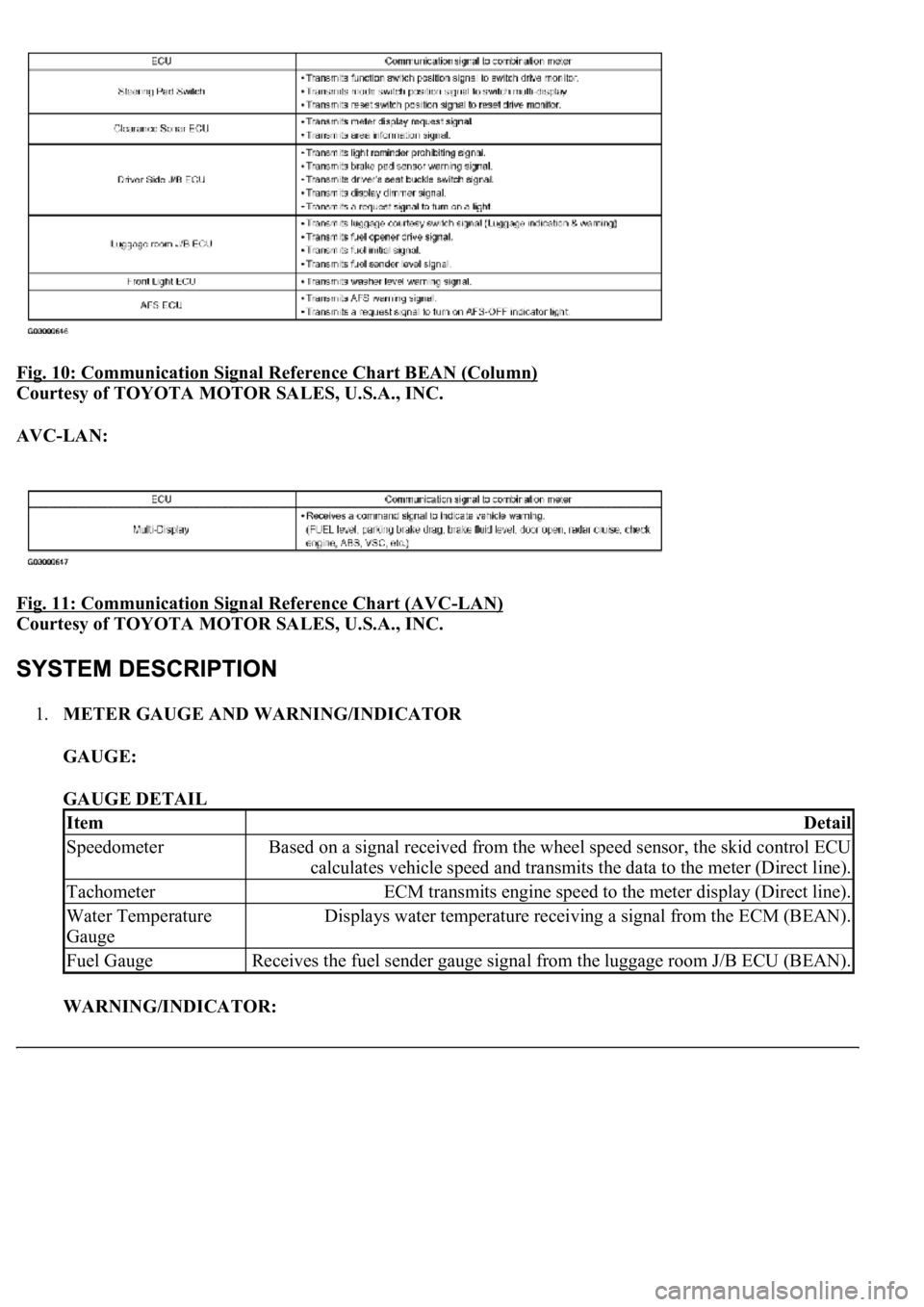
Fig. 10: Communication Signal Reference Chart BEAN (Column)
Courtesy of TOYOTA MOTOR SALES, U.S.A., INC.
AVC-LAN:
Fig. 11: Communication Signal Reference Chart (AVC
-LAN)
Courtesy of TOYOTA MOTOR SALES, U.S.A., INC.
1.METER GAUGE AND WARNING/INDICATOR
GAUGE:
GAUGE DETAIL
WARNING/INDICATOR:
ItemDetail
SpeedometerBased on a signal received from the wheel speed sensor, the skid control ECU
calculates vehicle speed and transmits the data to the meter (Direct line).
TachometerECM transmits engine speed to the meter display (Direct line).
Water Temperature
GaugeDisplays water temperature receiving a signal from the ECM (BEAN).
Fuel GaugeReceives the fuel sender gauge signal from the luggage room J/B ECU (BEAN).
Page 1744 of 4500
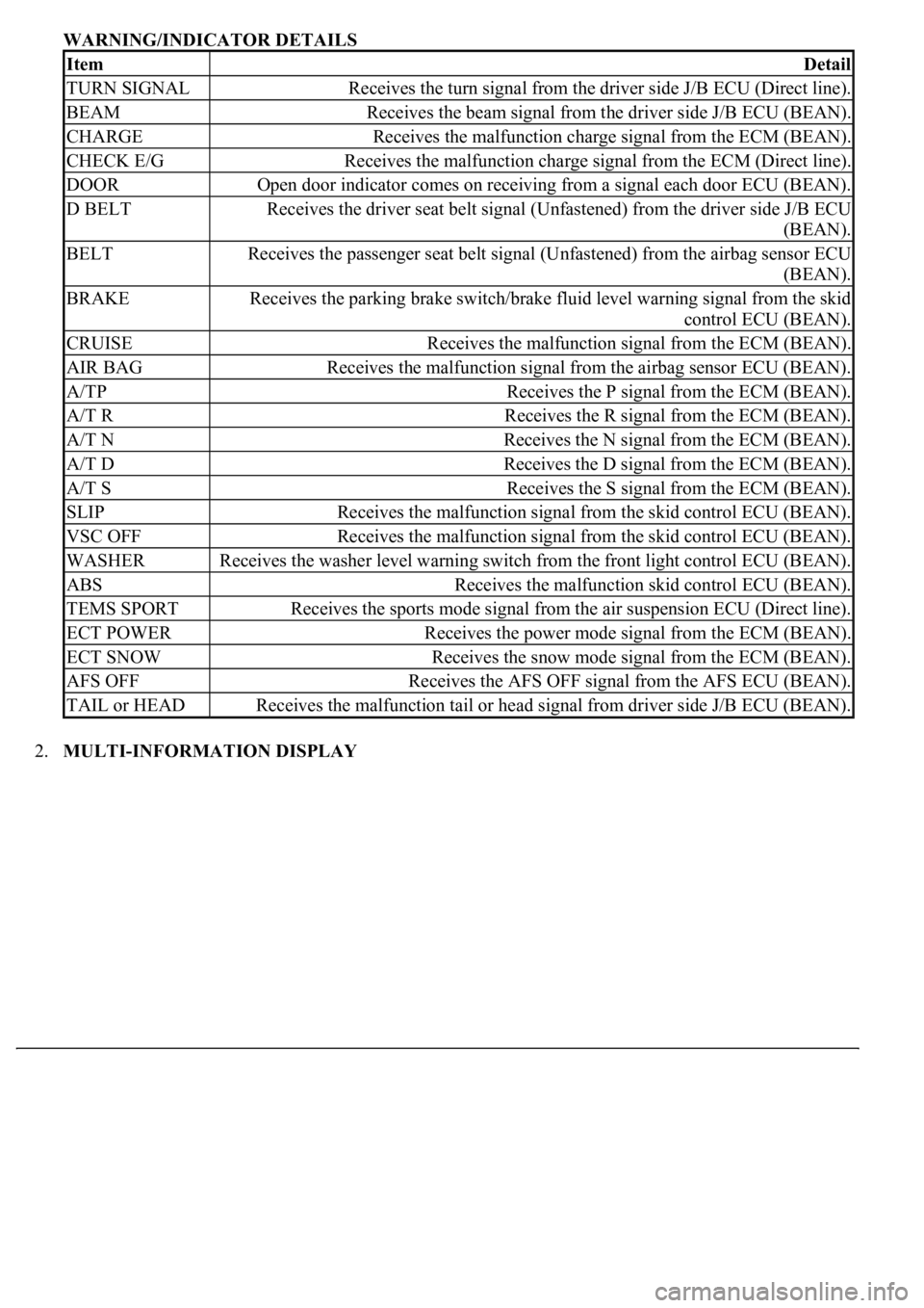
WARNING/INDICATOR DETAILS
2.MULTI-INFORMATION DISPLAY
ItemDetail
TURN SIGNALReceives the turn signal from the driver side J/B ECU (Direct line).
BEAMReceives the beam signal from the driver side J/B ECU (BEAN).
CHARGEReceives the malfunction charge signal from the ECM (BEAN).
CHECK E/GReceives the malfunction charge signal from the ECM (Direct line).
DOOROpen door indicator comes on receiving from a signal each door ECU (BEAN).
D BELTReceives the driver seat belt signal (Unfastened) from the driver side J/B ECU
(BEAN).
BELTReceives the passenger seat belt signal (Unfastened) from the airbag sensor ECU
(BEAN).
BRAKEReceives the parking brake switch/brake fluid level warning signal from the skid
control ECU (BEAN).
CRUISEReceives the malfunction signal from the ECM (BEAN).
AIR BAGReceives the malfunction signal from the airbag sensor ECU (BEAN).
A/TPReceives the P signal from the ECM (BEAN).
A/T RReceives the R signal from the ECM (BEAN).
A/T NReceives the N signal from the ECM (BEAN).
A/T DReceives the D signal from the ECM (BEAN).
A/T SReceives the S signal from the ECM (BEAN).
SLIPReceives the malfunction signal from the skid control ECU (BEAN).
VSC OFFReceives the malfunction signal from the skid control ECU (BEAN).
WASHERReceives the washer level warning switch from the front light control ECU (BEAN).
ABSReceives the malfunction skid control ECU (BEAN).
TEMS SPORTReceives the sports mode signal from the air suspension ECU (Direct line).
ECT POWERReceives the power mode signal from the ECM (BEAN).
ECT SNOWReceives the snow mode signal from the ECM (BEAN).
AFS OFFReceives the AFS OFF signal from the AFS ECU (BEAN).
TAIL or HEADReceives the malfunction tail or head signal from driver side J/B ECU (BEAN).
Page 1776 of 4500
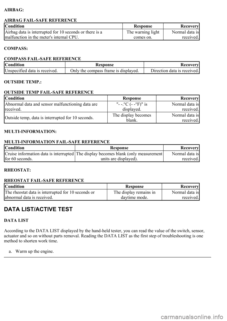
AIRBAG:
AIRBAG FAIL-SAFE REFERENCE
COMPASS:
COMPASS FAIL-SAFE REFERENCE
OUTSIDE TEMP.:
OUTSIDE TEMP FAIL-SAFE REFERENCE
MULTI-INFORMATION:
MULTI-INFORMATION FAIL-SAFE REFERENCE
RHEOSTAT:
RHEOSTAT FAIL-SAFE REFERENCE
DATA LIST
According to the DATA LIST displayed by the hand-held tester, you can read the value of the switch, sensor,
actuator and so on without parts removal. Reading the DATA LIST as the first step of troubleshooting is one
method to shorten work time.
a. Warm up the en
gine.
ConditionResponseRecovery
Airbag data is interrupted for 10 seconds or there is a
malfunction in the meter's internal CPU.The warning light
comes on.Normal data is
received.
ConditionResponseRecovery
Unspecified data is received.Only the compass frame is displayed.Direction data is received.
ConditionResponseRecovery
Abnormal data and sensor malfunctioning data are
received."- -.°C (- -°F)" is
displayed.Normal data is
received.
Outside temp, data is interrupted for 10 seconds.The display becomes
blank.Normal data is
received.
ConditionResponseRecovery
Cruise information data is interrupted
for 60 seconds.The display becomes blank (only measurement
units are displayed).Normal data is
received.
ConditionResponseRecovery
<0037004b004800030055004b004800520056005700440057000300470044005700440003004c00560003004c005100570048005500550058005300570048004700030049005200550003001400130003005600480046005200510047005600030052005500
03[
abnormal data is received.The display remains in
daytime mode.Normal data is
received.
Page 1779 of 4500
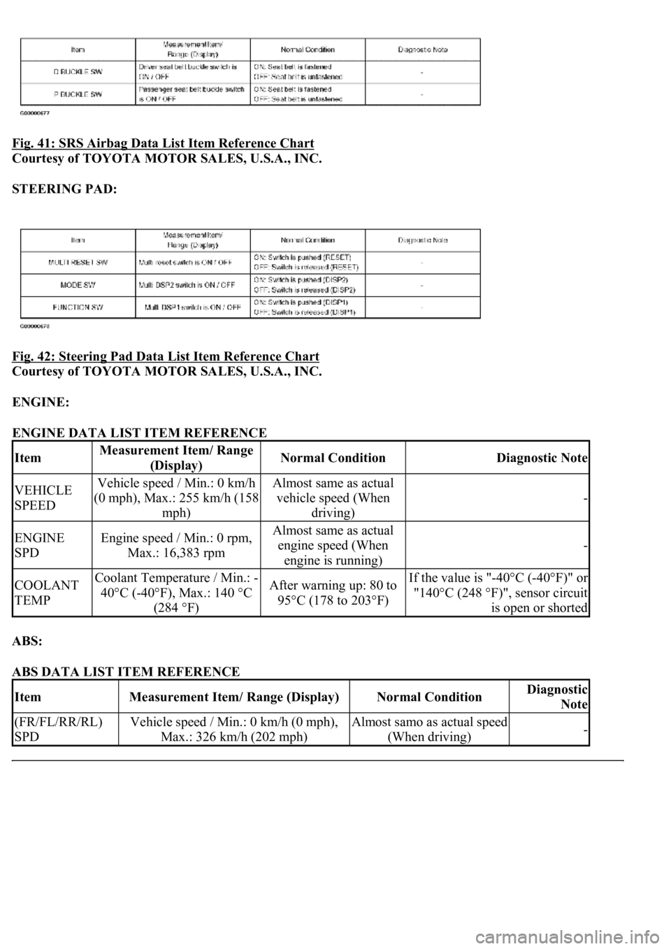
Fig. 41: SRS Airbag Data List Item Reference Chart
Courtesy of TOYOTA MOTOR SALES, U.S.A., INC.
STEERING PAD:
Fig. 42: Steering Pad Data List Item Reference Chart
Courtesy of TOYOTA MOTOR SALES, U.S.A., INC.
ENGINE:
ENGINE DATA LIST ITEM REFERENCE
ABS:
ABS DATA LIST ITEM REFERENCE
ItemMeasurement Item/ Range
(Display)Normal ConditionDiagnostic Note
VEHICLE
SPEEDVehicle speed / Min.: 0 km/h
(0 mph), Max.: 255 km/h (158
mph)Almost same as actual
vehicle speed (When
driving)
-
ENGINE
SPDEngine speed / Min.: 0 rpm,
Max.: 16,383 rpmAlmost same as actual
engine speed (When
engine is running)
-
COOLANT
TEMPCoolant Temperature / Min.: -
40°C (-40°F), Max.: 140 °C
(284 °F)After warning up: 80 to
95°C (178 to 203°F)If the value is "-40°C (-40°F)" or
"140°C (248 °F)", sensor circuit
is open or shorted
ItemMeasurement Item/ Range (Display)Normal ConditionDiagnostic
Note
(FR/FL/RR/RL)
SPDVehicle speed / Min.: 0 km/h (0 mph),
Max.: 326 km/h (202 mph)Almost samo as actual speed
(When driving)-