sensor LEXUS LS430 2003 Factory Repair Manual
[x] Cancel search | Manufacturer: LEXUS, Model Year: 2003, Model line: LS430, Model: LEXUS LS430 2003Pages: 4500, PDF Size: 87.45 MB
Page 1980 of 4500
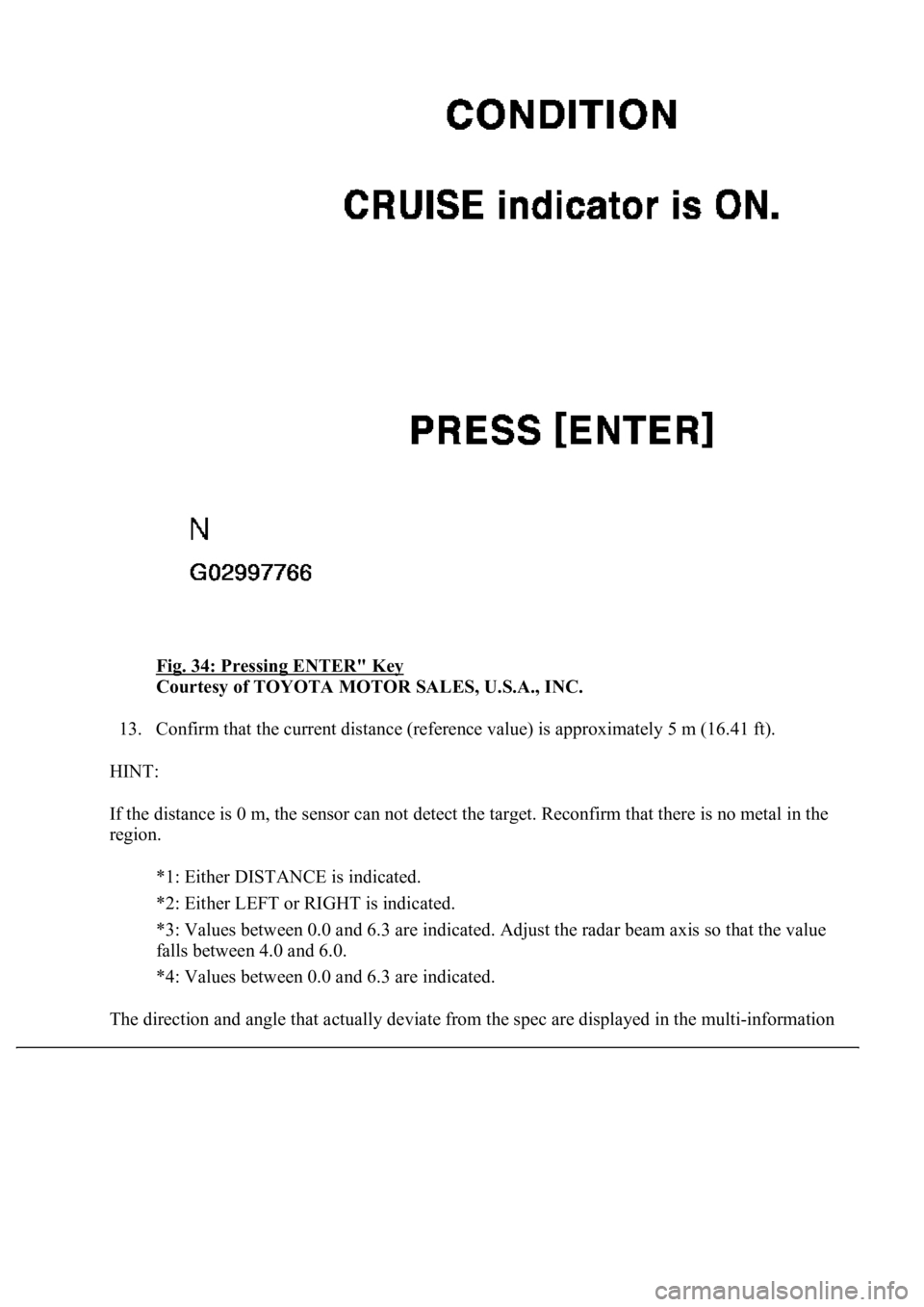
Fig. 34: Pressing ENTER" Key
Courtesy of TOYOTA MOTOR SALES, U.S.A., INC.
13. Confirm that the current distance (reference value) is approximately 5 m (16.41 ft).
HINT:
If the distance is 0 m, the sensor can not detect the target. Reconfirm that there is no metal in the
region.
*1: Either DISTANCE is indicated.
*2: Either LEFT or RIGHT is indicated.
<000d0016001d000300390044004f0058004800560003004500480057005a00480048005100030013001100130003004400510047000300190011001600030044005500480003004c00510047004c004600440057004800470011000300240047004d005800
56005700030057004b00480003005500440047004400550003[beam axis so that the value
falls between 4.0 and 6.0.
*4: Values between 0.0 and 6.3 are indicated.
The direction and angle that actually deviate from the spec are displayed in the multi-information
Page 1981 of 4500
display on the combination meter when starting the beam axis adjustment mode with the hand-held
tester.
Fig. 35: Confirming Current Distance
Courtesy of TOYOTA MOTOR SALES, U.S.A., INC.
g. Adjustment in horizontal direction
1. Read the divergence in the current angle.
Standard:
0° (Both right and left)
2. Based on the measured divergence of the beam axis, turn and adjust screw B for horizontal
adjustment of the millimeter wave radar sensor using a hexagon wrench.
HINT:
Page 1983 of 4500
Courtesy of TOYOTA MOTOR SALES, U.S.A., INC.
HINT:
If the value does not change to 0°, it is possible that the sensor is aiming at something
different. Reconfirm that there are no reflective materials in the surroundings.
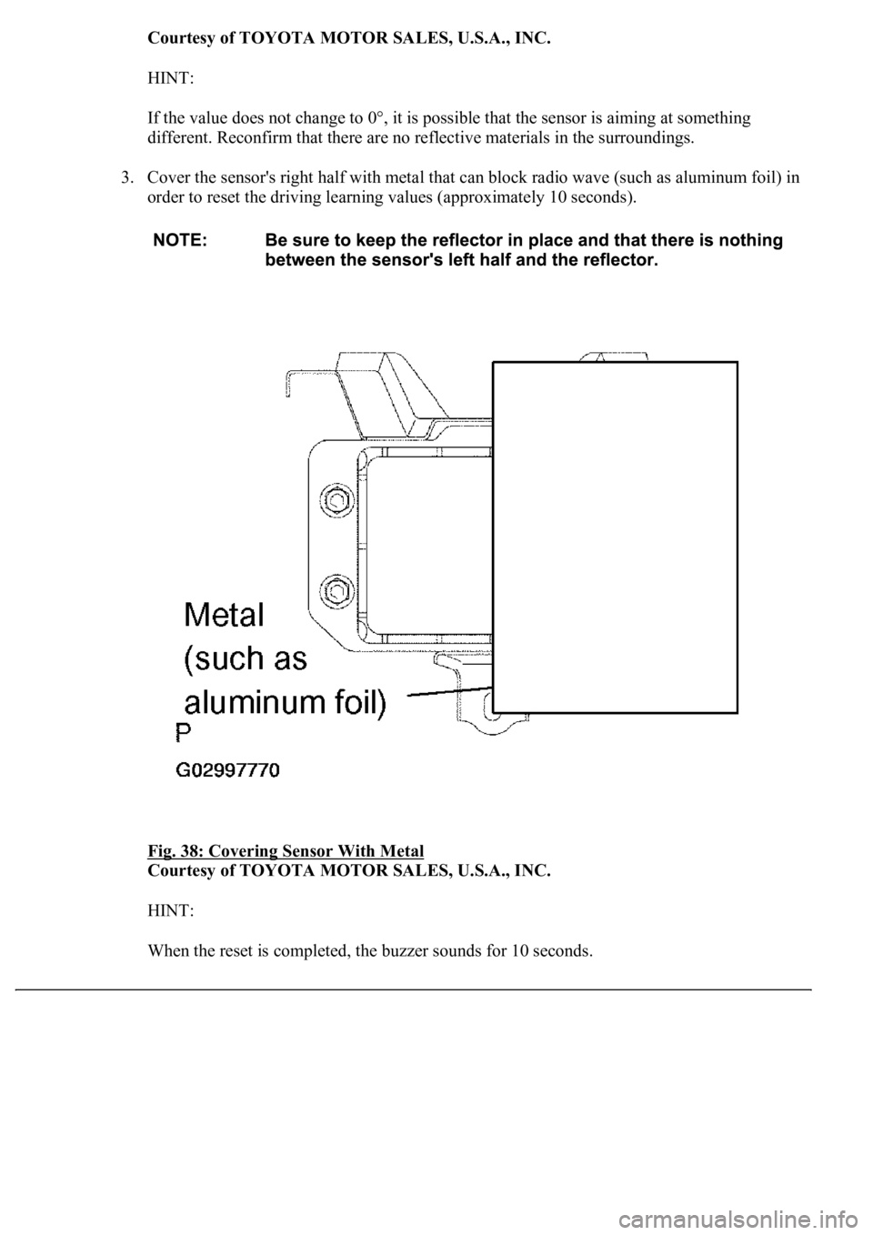
3. Cover the sensor's right half with metal that can block radio wave (such as aluminum foil) in
order to reset the driving learning values (approximately 10 seconds).
Fig. 38: Covering Sensor With Metal
Courtesy of TOYOTA MOTOR SALES, U.S.A., INC.
HINT:
When the reset is completed, the buzzer sounds for 10 seconds.
Page 1984 of 4500
4. Disconnect the hand-held tester from the DLC3.
h. Recheck vertical adjustment of the millimeter wave radar sensor.
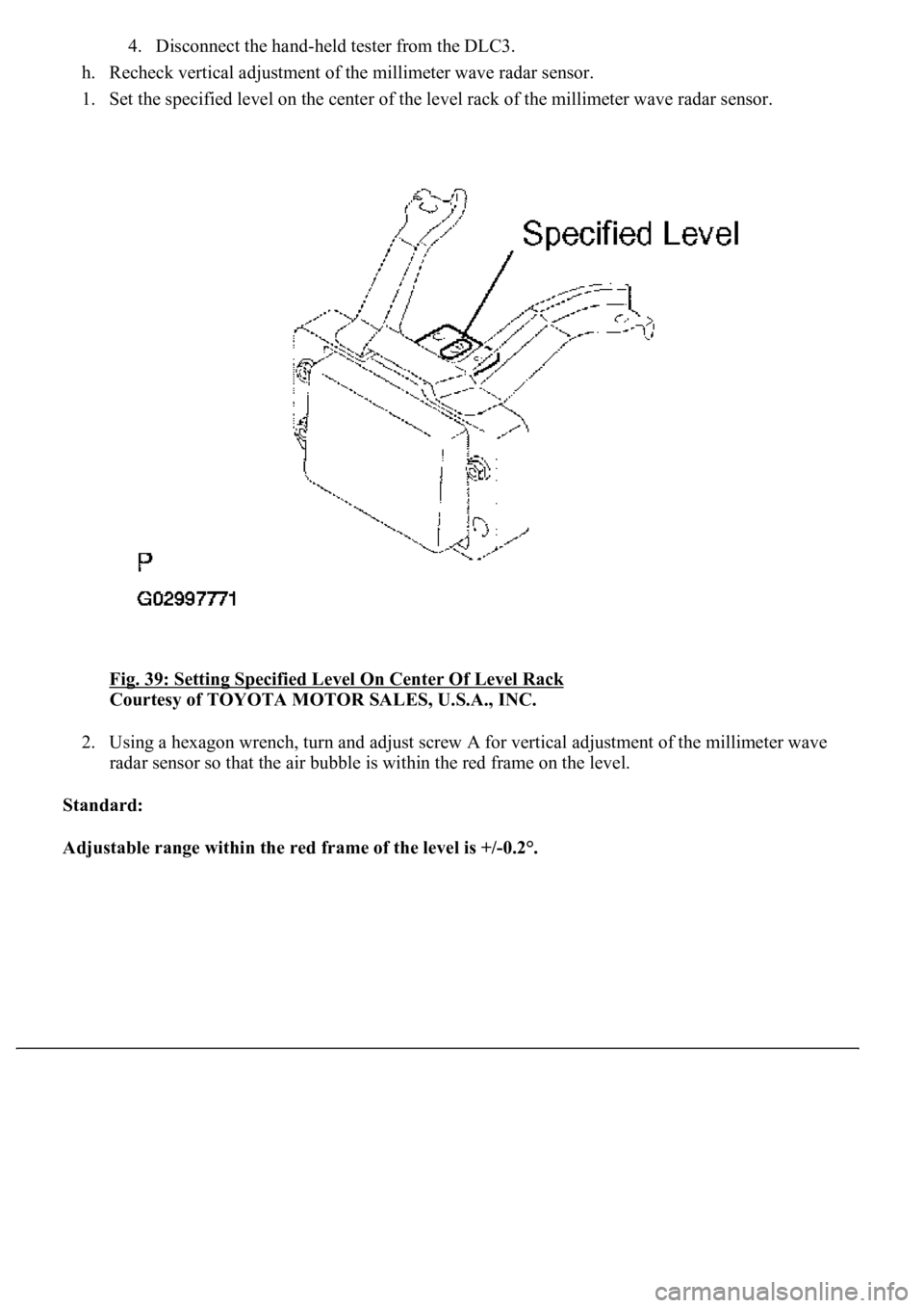
1. Set the specified level on the center of the level rack of the millimeter wave radar sensor.
Fig. 39: Setting Specified Level On Center Of Level Rack
Courtesy of TOYOTA MOTOR SALES, U.S.A., INC.
2. Using a hexagon wrench, turn and adjust screw A for vertical adjustment of the millimeter wave
radar sensor so that the air bubble is within the red frame on the level.
Standard:
Adjustable range within the red frame of the level is +/-0.2°.
Page 2011 of 4500
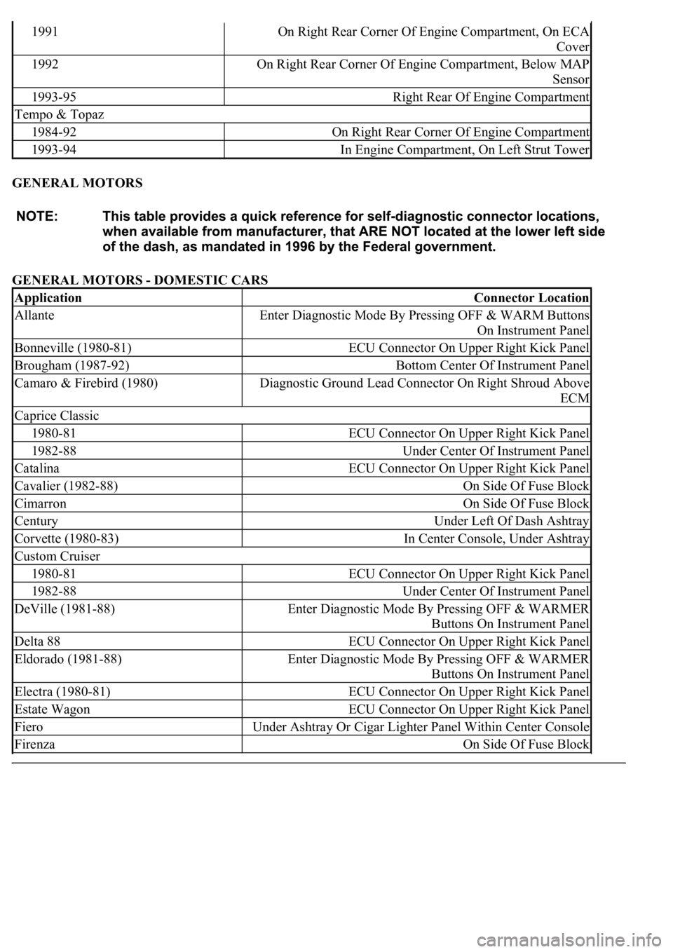
GENERAL MOTORS
GENERAL MOTORS - DOMESTIC CARS
1991On Right Rear Corner Of Engine Compartment, On ECA
Cover
1992On Right Rear Corner Of Engine Compartment, Below MAP
Sensor
1993-95Right Rear Of Engine Compartment
Tempo & Topaz
1984-92On Right Rear Corner Of Engine Compartment
1993-94In Engine Compartment, On Left Strut Tower
ApplicationConnector Location
AllanteEnter Diagnostic Mode By Pressing OFF & WARM Buttons
On Instrument Panel
Bonneville (1980-81)ECU Connector On Upper Right Kick Panel
Brougham (1987-92)Bottom Center Of Instrument Panel
Camaro & Firebird (1980)Diagnostic Ground Lead Connector On Right Shroud Above
ECM
Caprice Classic
1980-81ECU Connector On Upper Right Kick Panel
1982-88Under Center Of Instrument Panel
CatalinaECU Connector On Upper Right Kick Panel
Cavalier (1982-88)On Side Of Fuse Block
CimarronOn Side Of Fuse Block
CenturyUnder Left Of Dash Ashtray
Corvette (1980-83)In Center Console, Under Ashtray
Custom Cruiser
1980-81ECU Connector On Upper Right Kick Panel
1982-88Under Center Of Instrument Panel
DeVille (1981-88)Enter Diagnostic Mode By Pressing OFF & WARMER
Buttons On Instrument Panel
Delta 88ECU Connector On Upper Right Kick Panel
Eldorado (1981-88)Enter Diagnostic Mode By Pressing OFF & WARMER
Buttons On Instrument Panel
Electra (1980-81)ECU Connector On Upper Right Kick Panel
Estate WagonECU Connector On Upper Right Kick Panel
FieroUnder Ashtray Or Cigar Lighter Panel Within Center Console
FirenzaOn Side Of Fuse Block
Page 2020 of 4500
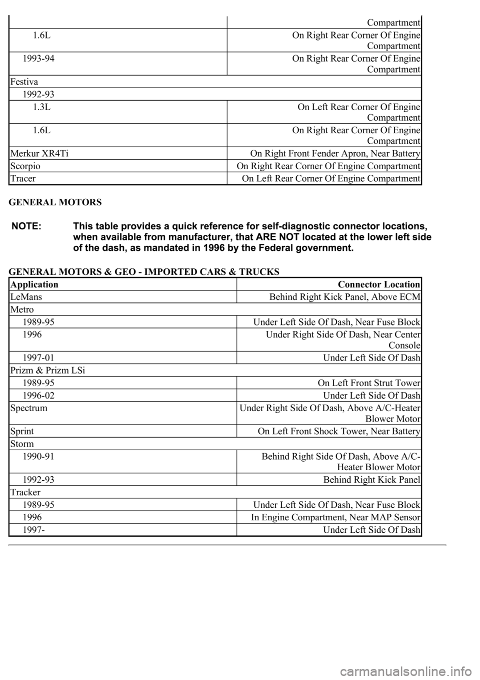
GENERAL MOTORS
GENERAL MOTORS & GEO - IMPORTED CARS & TRUCKS
Compartment
1.6LOn Right Rear Corner Of Engine
Compartment
1993-94On Right Rear Corner Of Engine
Compartment
Festiva
1992-93
1.3LOn Left Rear Corner Of Engine
Compartment
1.6LOn Right Rear Corner Of Engine
Compartment
Merkur XR4TiOn Right Front Fender Apron, Near Battery
ScorpioOn Right Rear Corner Of Engine Compartment
TracerOn Left Rear Corner Of Engine Compartment
ApplicationConnector Location
LeMansBehind Right Kick Panel, Above ECM
Metro
1989-95Under Left Side Of Dash, Near Fuse Block
1996Under Right Side Of Dash, Near Center
Console
1997-01Under Left Side Of Dash
Prizm & Prizm LSi
1989-95On Left Front Strut Tower
1996-02Under Left Side Of Dash
SpectrumUnder Right Side Of Dash, Above A/C-Heater
Blower Motor
SprintOn Left Front Shock Tower, Near Battery
Storm
1990-91Behind Right Side Of Dash, Above A/C-
Heater Blower Motor
1992-93Behind Right Kick Panel
Tracker
1989-95Under Left Side Of Dash, Near Fuse Block
1996In Engine Compartment, Near MAP Sensor
1997-Under Left Side Of Dash
Page 2033 of 4500
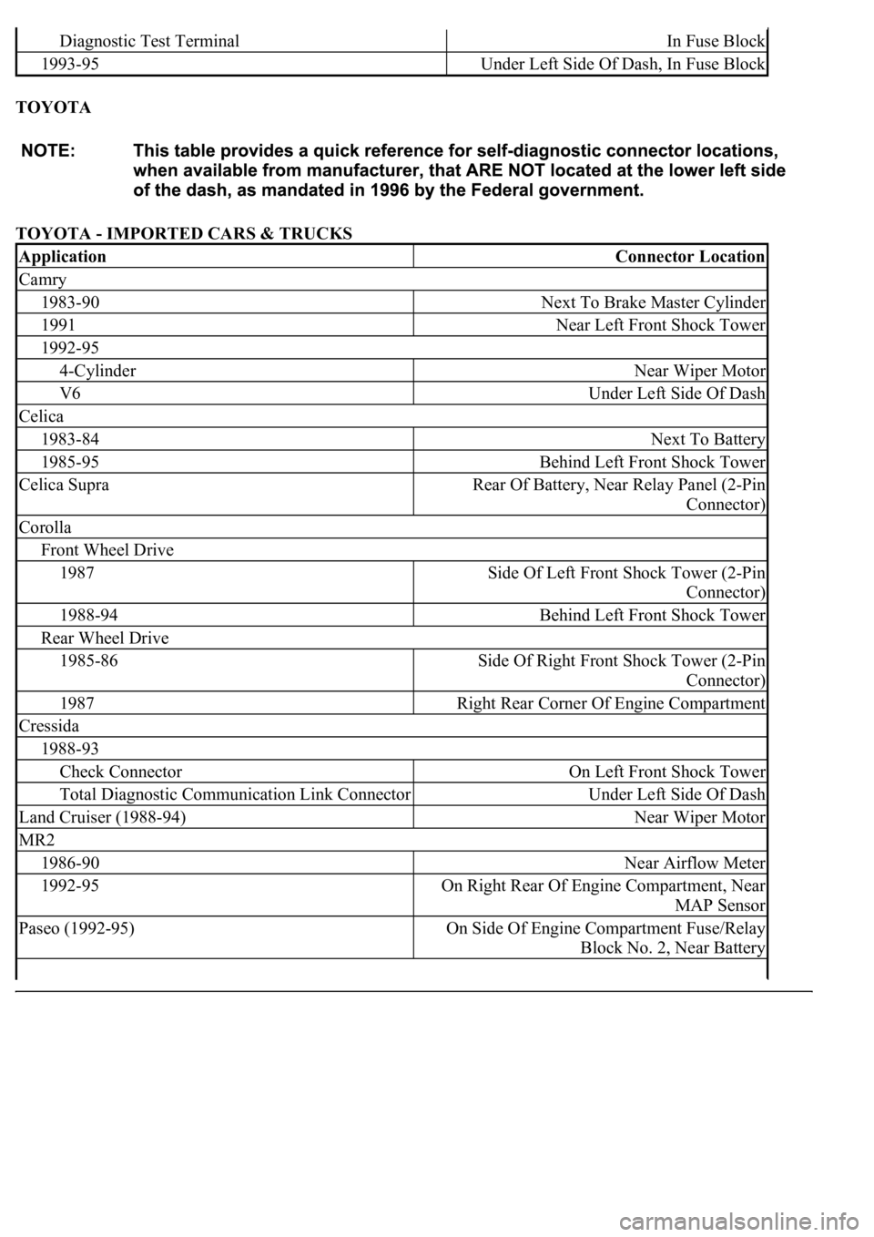
TOYOTA
TOYOTA - IMPORTED CARS & TRUCKS
Diagnostic Test TerminalIn Fuse Block
1993-95Under Left Side Of Dash, In Fuse Block
ApplicationConnector Location
Camry
1983-90Next To Brake Master Cylinder
1991Near Left Front Shock Tower
1992-95
4-CylinderNear Wiper Motor
V6Under Left Side Of Dash
Celica
1983-84Next To Battery
1985-95Behind Left Front Shock Tower
Celica SupraRear Of Battery, Near Relay Panel (2-Pin
Connector)
Corolla
Front Wheel Drive
1987Side Of Left Front Shock Tower (2-Pin
Connector)
1988-94Behind Left Front Shock Tower
Rear Wheel Drive
1985-86Side Of Right Front Shock Tower (2-Pin
Connector)
1987Right Rear Corner Of Engine Compartment
Cressida
1988-93
Check ConnectorOn Left Front Shock Tower
Total Diagnostic Communication Link ConnectorUnder Left Side Of Dash
Land Cruiser (1988-94)Near Wiper Motor
MR2
1986-90Near Airflow Meter
1992-95On Right Rear Of Engine Compartment, Near
MAP Sensor
Paseo (1992-95)On Side Of Engine Compartment Fuse/Relay
Block No. 2, Near Battery
Page 2045 of 4500
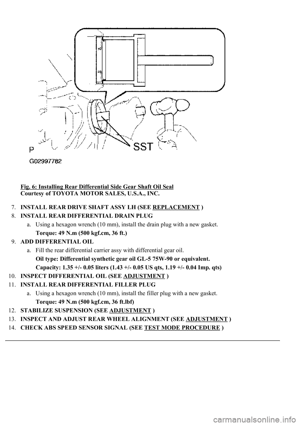
Fig. 6: Installing Rear Differential Side Gear Shaft Oil Seal
Courtesy of TOYOTA MOTOR SALES, U.S.A., INC.
7.INSTALL REAR DRIVE SHAFT ASSY LH (SEE REPLACEMENT
)
8.INSTALL REAR DIFFERENTIAL DRAIN PLUG
a. Using a hexagon wrench (10 mm), install the drain plug with a new gasket.
Torque: 49 N.m (500 kgf.cm, 36 ft.)
9.ADD DIFFERENTIAL OIL
a. Fill the rear differential carrier assy with differential gear oil.
Oil type: Differential synthetic gear oil GL-5 75W-90 or equivalent.
<00260044005300440046004c0057005c001d000300140011001600180003000e00120010000300130011001300180003004f004c00570048005500560003000b00140011001700160003000e00120010000300130011001300180003003800360003005400
570056000f0003001400110014001c0003000e001200100003[0.04 Imp. qts)
10.INSPECT DIFFERENTIAL OIL (SEE ADJUSTMENT
)
11.INSTALL REAR DIFFERENTIAL FILLER PLUG
a. Using a hexagon wrench (10 mm), install the filler plug with a new gasket.
Torque: 49 N.m (500 kgf.cm, 36 ft.lbf)
12.STABILIZE SUSPENSION (SEE ADJUSTMENT
)
13.INSPECT AND ADJUST REAR WHEEL ALIGNMENT (SEE ADJUSTMENT
)
14.CHECK ABS SPEED SENSOR SIGNAL (SEE TEST MODE PROCEDURE
)
Page 2177 of 4500
a. Fill the rear differential carrier assy with differential gear oil equivalent.
Oil type: Differential synthetic gear oil GL-5 75W-90 or equivalent
Capacity: 1.35 +/- 0.05 liters (1.43 +/- 0.05 US qts, 1.19 +/- 0.04 Imp. qts)
67.INSPECT DIFFERENTIAL OIL (SEE ADJUSTMENT
)
68.INSTALL REAR DIFFERENTIAL FILLER PLUG
a. Using a hexagon wrench (10 mm), install the filler plug with a new gasket.
Torque: 49 N.m (500 kgf.cm, 36 ft.lbf)
69.INSTALL REAR DRIVE SHAFT ASSY LH (SEE REPLACEMENT
)
70.INSTALL REAR DRIVE SHAFT ASSY RH
HINT:
Installation procedure of the RH side is the same as that of the LH side.
71.INSTALL FRONT FLOOR HEAT INSULATOR NO.1
a. Install the front floor heat insulator No.1 with the 4 bolts.
Torque: 5.4 N.m (55 kgf.cm, 48 in..lbf)
72.INSTALL REAR WHEEL
a. Install the rear wheel with the 5 nuts.
Torque: 103 N.m (1,050 kgf.cm, 76 ft.lbf)
73. Install the ornament with the 10 bolts.
Torque: 20 N.m (204 kgf.cm, 15 ft.lbf)
74.INSTALL PROPELLER W/CENTER BEARING SHAFT ASSY (SEE OVERHAUL
)
75.FULLY TIGHTEN CENTER SUPPORT BEARING ASSY NO.1 (SEE OVERHAUL
)
SST 09922-10010
76.INSPECT AND ADJUST NO.2 AND NO.3 JOINT ANGLE (SEE OVERHAUL
)
77.INSTALL PROPELLER SHAFT HEAT INSULATOR (SEE OVERHAUL
)
78.INSTALL EXHAUST PIPE ASSY (SEE REPLACEMENT
)
79.INSTALL OXYGEN SENSOR (SEE REPLACEMENT
)
80.INSPECT AND ADJUST REAR WHEEL ALIGNMENT (SEE ADJUSTMENT
)
81.ADJUST VEHICLE HEIGHT (W/ AIR SUSPENSION) (SEE ON
-VEHICLE INSPECTION )
82.INSPECT HEADLIGHT AIM ONLY (SEE ADJUSTMENT
)
83.CHECK ABS SPEED SENSOR SIGNAL (SEE TEST MODE PROCEDURE
)
84.INSPECT AIR LEAK (W/ AIR SUSPENSION) (SEE REPLACEMENT
)
HINT:
Perform this operation onl
y when the rear differential mount cushion is replaced.
Page 2198 of 4500

Courtesy of TOYOTA MOTOR SALES, U.S.A., INC.
2.CLEAR DTC
a. Connect the hand-held tester to the Controller Area Network Vehicle Interface Module (CAN
VIM). Then connect the CAN VIM to the DLC3.
b. Turn the ignition switch ON.
c. Erase the DTCs by following the prompts on the tester screen.
HINT:
Refer to the hand-held tester operator's manual for further details.
1.DATA LIST
HINT:
Using the hand-held tester's DATA LIST allows switch, sensor, actuator and other item values to be read
without removing any parts. Reading the DATA LIST early in troubleshooting is one way to save time.
1. Connect the hand-held tester (with CAN VIM) to the DLC3.
2. Turn the ignition switch ON.
3. Read the DATA LIST on the tester's screen.
DRIVER DOOR ECU, PASSENGER DOOR ECU, REAR DOOR ECU LH AND REAR DOOR
ECU RH DATA LIST
Item
Measurement item/Display
(Range)
Normal ConditionDiagnostic Note
CAM POS SW3Cam position switch 3 signal/
ON or OFFRefer to system description of
closer motor and cam position
switch (SEE SYSTEM
DESCRIPTION )
-
CAM POS SW2Cam position switch 2 signal/
ON or OFFRefer to system description of
closer motor and cam position
switch (SEE SYSTEM
DESCRIPTION )
-
CAM POS SW1Cam position switch 1 signal/
ON or OFFRefer to system description of
closer motor and cam position
switch (SEE SYSTEM
DESCRIPTION )
-
POLE SWPawl switch signal/ ON or OFFRefer to system description of
door ECU (SEE SYSTEM
DESCRIPTION )
-
HALF SWHalf switch signal/ ON or OFFRefer to system description of -